Abstract
Earthquakes have serious destructive effects on building structures, and effective seismic design is the key to building design. In order to reduce the damage of earthquakes to building structures, seismic design of buildings is based on improved viscous dampers. First, the displacement seismic design was studied and a displacement-based structural seismic model was constructed. In addition, analyzing traditional viscous dampers, an improved viscous damper is adopted based on it. Through equivalent damping expression, a displacement seismic model based on the improved viscous damper is constructed. Finally, two targets, frequent and rare earthquakes, were selected for experimental analysis. In frequent earthquake experiments, the improved viscous damper structure increased the shock absorption rate by 35.65 % compared to the no-structure design. In the shear force comparison, the maximum shear force of the improved viscous damper structure in the HB wave X direction is 2186 KN, which is the smallest shear force among the three structural designs. In a rare earthquake experiment, the maximum value of the floor shear force in the X-direction of the Humbolt bay wave of the proposed improved viscous damper structure was 8696 KN. Compared with other structures, the floor shear force was the smallest. In the comparison of floor displacements, the maximum inter-story displacement in the Humbolt bay wave Y-direction of the proposed improved viscous damper structure is 162 mm, which is the smallest inter-story displacement compared with other structures. In addition, the structure apex displacement was also compared. The structure apex displacement value of the improved viscous damper structure was lower than that of other structures and was in the slight damage range. The overall seismic effect was significantly better than other structural designs. The research content is conducive to optimizing the application effect of viscous dampers and provides technical reference for the seismic design of building structures.
1. Introduction
The destructiveness of earthquakes to building structures often brings huge disasters to people, so the seismic design of buildings becomes particularly important. In recent years, with the advancement of science and technology and in-depth research, the seismic design of buildings based on displacement has gradually attracted attention. Compared with traditional design methods, displacement seismic design has many technical features and advantages. For example, traditional seismic design often only considers the stiffness and strength of the structure, while displacement seismic design pays more attention to the displacement response of the structure to earthquakes, which can better protect the integrity of the building and the safety of personnel. Secondly, displacement-based seismic design can more accurately evaluate the seismic performance of the structure by building a seismic model. It not only considers the overall stiffness of the structure, but also considers the displacement distribution and shape of the structure under earthquake action. By analyzing and studying displacements, the behavior of buildings in earthquakes can be better predicted, thereby optimizing and improving design solutions. However, the displacement design based on viscous dampers still has shortcomings, and its effect is easily limited by small deformation factors. Therefore, based on displacement seismic design, an improved amplified viscous damper is introduced for seismic structural design. Research and technological innovation are mainly reflected in two aspects. Firstly, based on displacement seismic design, the stability, durability, and adaptability requirements of the building structure are fully considered in the structural design, ensuring the effectiveness of the structural design. Secondly, traditional viscous dampers have been improved to fully consider more seismic scenarios and better adapt to different seismic conditions, thereby improving overall seismic performance. The significance of the research is that through the research and improvement of displacement seismic design, the seismic performance of building structures in earthquakes can be improved, the losses of earthquake disasters can be reduced, and technical guidance can be provided for the structural seismic design of related buildings.
The research content is divided into four parts. The first part introduces the relevant cutting-edge technologies and applications of building seismic design. The second part studies the seismic design of buildings, analyzes related technologies based on displacement seismic design, and builds related models. The third part conducts performance testing of the proposed building anti-seismic technology to verify its application effect in actual scenarios. The fourth part summarizes and analyzes the full text and elaborates on the improvement direction of the research.
2. Related works
Earthquakes have a fatal impact on building structures. They will not only destroy the structure of the building itself, but also affect the safety of users. Therefore, the design of seismic structures of buildings has attracted much attention [1-3]. Muttoni and others found that punching failure is a controlled failure mode of flat plate frames, and structural limitations can easily lead to building collapse. In order to solve the above problems, the punching shear Eq. of concrete structures was studied and a closed expression was obtained, which can be used to predict the deformation capacity of internal slab-column connections. Finally, corresponding experimental analysis was carried out, and this technology was applied to optimize and improve the building structure, and the overall seismic resistance of the building was significantly improved [4]. Zhong and Christopoulos conducted research on early building structures, in which the self-centered seismic knot design can effectively reduce earthquake damage and residual drift. Therefore, in order to effectively improve the structural seismic resistance of buildings, further research is conducted on self-centered seismic knots and applied to the seismic process of buildings. Through the optimization and adjustment of building structural parameters, the seismic effect of building structures can be further improved. Specific experiments show that this technology has good seismic performance in building structures and is better than similar related technologies [5]. Alam et al. found that asymmetric structures are more susceptible to earthquake damage under earthquake action. Further research found that mainly due to coupled torsional vibration, it will cause destructive effects on the building structure, thereby affecting the stability of the building. In order to solve the above problems, a correlation experimental analysis was carried out on the eccentric quarter-scale asymmetric structure, and a fiber Bragg grating sensor was used to detect structural damage. Finally, a finite element model was established and the results of the model and experiments were compared. Through relevant experimental discussions, we have a better understanding of the mechanism of asymmetric structures in building seismic resistance, which is conducive to strengthening the overall seismic resistance of building structures [6].
In recent years, viscous dampers have become one of the key technologies in seismic design of building structures. The viscous damper adopts advanced manufacturing technology and materials, which can withstand various vibration and impact tests, and exhibits extremely high reliability in terms of service life. Therefore, relevant scholars have conducted research on it. Hu et al. proposed a building seismic design using viscous dampers to improve building seismic performance. However, the parameter distribution between the damper installation locations was not fully considered in the design. In order to solve the above problems, a distribution pattern is adopted that can reduce the overall requirement of building coefficient without changing the response mitigation effect. In the relevant experimental analysis, by establishing a model and conducting simulation experiments, the researched technology has better anti-seismic effects in actual scenarios compared with similar technologies [7]. De Domenico D. et al. proposed a practical nonlinear viscous damper building seismic optimization method to realize the transformation of steel frame structures. First, the Maxwell model was used to simulate the damper performance. During the design process, the nonlinearity of the parent steel frame was considered to determine the performance optimization parameters of the building. The results show that the research technology has excellent stability and lower building damage [8]. Akehashi and Takewaki proposed a method to determine the optimal location of a target viscous damper. The first choice is to study the parameters of the building, obtain the building structure model, and design a model optimization adjustment technology based on the building optimization objective function. Deep learning algorithms are used to solve the target. The proposed technology has excellent seismic performance in real scenarios [9]. Karami and others found that in areas with strong earthquakes, housing buildings face the threat of serious earthquake damage. In order to ensure the safety of area residents, it is particularly critical to carry out structural seismic design. In this regard, a numerical design optimization method is proposed to use nonlinear viscous dampers for seismic reinforcement of existing steel frames to achieve seismic optimization of building structures [10]. Humaidi et al. conducted a study on the seismic performance of building structures, with the aim of reducing the damage of seismic excitation to building structures. Therefore, the bee algorithm was introduced in the study to adjust the gain of traditional PID controllers, thereby achieving active control of two-story building structures. In addition, the research also continuously optimizes the structural design parameters by calculating the excitation parameters between different floors. Finally, relevant seismic models were used for experiments, and this technology has good feasibility [11].
In addition, many scholars have conducted extensive research on the mechanical performance analysis of seismic resistant structural materials. Scholars such as Jain et al. have studied traditional foundation isolators and found that there is a significant relative displacement between these components and the foundation. Therefore, further study the attenuation characteristics and investigate their periodic characteristics. Simultaneously, the periodic fundamental bandgap characteristics are calculated using the plane wave expansion method. Through this study, the seismic characteristics of different materials will be effectively analyzed, and support will be provided for the seismic resistance of building structures [12]. Pany and Li have studied periodic repetitive crystal materials in Jining, which are widely used in various aerospace, industrial, and building structural processes to ensure their excellent quality performance. At the same time, the numerical method of finite element theory was used to construct a physical model in the study, in order to analyze the mechanical condition of the structure on multiple surfaces. Obtained a three-dimensional graph related to the phase constant, flutter frequency, and pressure parameters corresponding to the optimal period angle. The research will also provide reference for seismic optimization design of building structures [13]. Hu et al. have conducted research on seismic design of building structures, and in order to improve the seismic performance of buildings, a structural design scheme using viscous dampers has been adopted. Among them, an optimized damping distribution pattern was adopted, which can reduce the overall requirement for damping coefficient without changing the response mitigation effect. In addition, the seismic demand ratio of each floor was analyzed to optimize different types of design responses. The final test results show that the design has good seismic performance and a simple structure [7]. Pany and Parthan analyzed the one-dimensional axial wave propagation in an infinitely long period supported cylindrical curved panel under the action of supersonic airflow. The study used aerodynamic analysis based on piston theory to analyze the performance of cylindrical curved panel structures, while using both precise and finite element methods to analyze flutter frequency and pressure parameters. Through the above analysis, technical support is provided for the optimization of seismic resistant structures in buildings [14].
According to the above research, it can be seen that effective building seismic design is the key to reducing earthquake disaster damage. In the seismic design of buildings, displacement-based seismic design has excellent application effects. The use of viscous dampers can significantly reduce earthquake displacement damage and minimize earthquake risks. However, the above-mentioned literature research did not consider the adaptability of traditional seismic design in rare and frequent scenarios. Therefore, a more advanced viscous damper was adopted in the subsequent research on seismic design, taking into account different seismic scenarios. Applying it to common and frequent earthquake scenarios to improve the overall seismic design effect of buildings.
3. Construction of building seismic model based on displacement
This part mainly studies the seismic design of structures based on displacement and builds related models. At the same time, the shortcomings of the traditional viscous damper are analyzed, an improved viscous damper is introduced, and a displacement-based seismic model is constructed.
3.1. Building seismic design based on displacement design
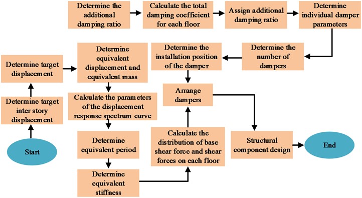
In recent years, more and more large-scale buildings have been built. In architectural design and construction, earthquake-resistant design of buildings is the key to construction. Among them, the structural seismic design based on displacement has attracted much attention. Compared with the traditional seismic design based on load-bearing, displacement control pays more attention to the performance and seismic resistance of the building, which is more obvious for the stability and safety of the building structure [15]. In displacement based design, equating multi degree of freedom structures to single degree of freedom is the key to seismic design, mainly because the application of multi degree of freedom equivalence can reduce the difficulty of subsequent calculations and improve the effectiveness of structural design. The principle of displacement seismic design is shown in Fig. 1.
Fig. 1Principle of displacement seismic design
In displacement-based seismic design, it is necessary to determine the performance objectives of the structure, such as considering building stability, durability, and adaptability conditions, etc., and comprehensively determine the performance design requirements based on various factors. In the study, both frequent and rare cases were considered for design. Based on the maximum elastic inter story displacement to floor height ratio of the frame not exceeding 1/550, the inter story displacement angle in frequent cases was set at 1/550. For rare cases, to prevent damage from characteristic earthquakes, the inter story displacement angle was set at 1/100 [16]. In displacement-based design, equating multi-degree-of-freedom structures into single degrees of freedom is the key to seismic design. The equivalent principle of building degrees of freedom is shown in Fig. 2 [17].
Fig. 2Equivalent principle of structural degrees of freedom
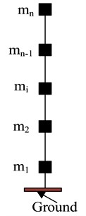
a) Multi degree of freedom system
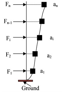
b) Acceleration and inertial force
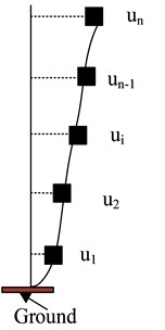
c) Displacement shape
In the design of building structures, the building's multi-degree-of-freedom dynamic system is shown in Eq. (1):
where, M represents the mass matrix, K represents the stiffness matrix, C represents the damping matrix, ¨U, ˙U, and U represent different velocities under three degrees of freedom: multi degree of freedom system, acceleration and inertial force, and displacement shape. ¨ug(t) representing inertial force. The lateral shift state of the multi-degree-of-freedom system is defined as Eq. (2):
where, Z(t) represents the normalized coordinates and Φ(ξ) represents the mode matrix. By bringing Eq. (1) and Eq. (2) into the solution, the normalized structural dynamic Eq. can be obtained, such as Eq. (3):
In the equivalent degree of freedom system, set the equivalent displacement as ueff, the equivalent acceleration as aeff, the equivalent mass as Meff, the equivalent base shear force as Vb, and the equivalent stiffness as keff, then the ui equation of multi-degree-of-freedom particle lateral displacement and equivalent displacement ueff is shown in Eq. (4):
where, ai represents the absolute acceleration of the particle. The seismic force exerted on the multi-degree-of-freedom particle i at this moment is shown in Eq. (5):
where, mi represents the particle mass. The equivalent base shear force can then be calculated, as shown in Eq. (6):
The equivalent mass can be further obtained from Eq. (5) and Eq. (6), as shown in Eq. (7):
Through the Eq. (7), i the seismic force on the final particle can be obtained, as shown in Eq. (8):
where, mj and uj are the single-degree-of-freedom particle mass and equivalent displacement respectively. Under the action of earthquake excitation, the work done by single degree of freedom and multiple degrees of freedom are the same, and there is Eq. (9):
According to Eq. (8) and Eq. (9), the equivalent displacement can be obtained, as shown in Eq. (10):
In addition, in displacement-based seismic design, the equivalent period also needs to be determined Teff, which needs to be obtained by constructing a displacement response spectrum. The seismic integral curve is used to construct the displacement response spectrum, and the seismic integral curve is shown in Fig. 3.
Fig. 3Seismic integration curve
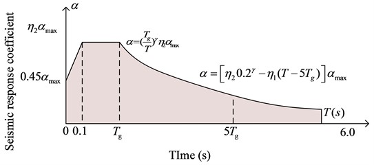
In order to obtain the displacement response spectrum, the dynamic differential equation of the equivalent degree of freedom system is set as ¨u(t)+2ξω˙u(t)+ω2u(t)=-¨ug(t), where and 2ξ are ω both damping term parameters, ¨u(t) representing multi-degree-of-freedom acceleration, and u(t) multi-degree-of-freedom displacement, u(t) representing the displacement under multi-degree of freedom. Due to the fact that the Duhamet integral is an effective method for solving the response of linear systems under arbitrary external excitation, which improves computational efficiency, the displacement obtained by using the Duhamet integral is shown in Eq. (11) [18]:
where, T represents the seismic response period and τ represents the interval time, which can be obtained by using the second-order derivative ¨u(t), as shown in Eq. (12):
According to the Eq. (12), the acceleration response spectrum can be obtained, as shown in Eq. (13):
where, αl represents the seismic response coefficient, Sa which is the spectral acceleration, g represents the gravity acceleration, which Sd is the single-degree-of-freedom spectral displacement. The earthquake response period can be obtained from the displacement spectrum, and the period expression is shown in Eq. (14):
In Eq. (14), η2 represents the damping adjustment coefficient.
3.2. Construction of displacement seismic model based on amplified viscous damping structure
In the displacement-based seismic structural design, in order to reduce the impact of earthquakes on the building structure, appropriate dampers need to be used to reduce the impact of earthquakes on the building. Considering that the research object is concrete steel frame concrete structure buildings, viscous dampers (Viscous Damper, VD) have excellent seismic effects in the seismic resistance of steel frames, concrete frames and other structures [19]. Therefore, viscous dampers are used as the main structure for anti-seismic design. However, traditional viscous dampers have limited energy consumption and poor shock absorption effects in scenarios where structural deformation is small. Therefore, in order to solve the above problems, an Amplified Viscous Damper (Amplified Viscous Damper, AVD) displacement seismic method [20]. The schematic diagram of the enlarged damper device is shown in Fig. 4.
Fig. 4A new type of amplified damper device
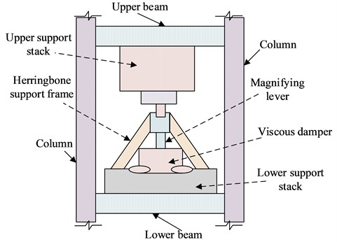
According to the structure of Fig. 4, the device consists of a horizontally placed viscous damper, a vertical amplification lever and a herringbone bracket. In order to analyze the mechanical model of AVD, the AVD mechanical model will be obtained through nonlinear derivation of VD. Suppose the structural velocity is ˙u, the structural displacement is u, and by using the lever device to amplify it n times, the amplified displacement is uf=n*u, and the speed is ˙uf=n*˙u. Where and are ˙uf input uf into the nonlinear viscous damper model, and the AVD damping force expression is obtained as shown in Eq. (15):
where, c represents the damping coefficient, α represents the damping coefficient. Using the lever amplification effect, the AVD mechanical model is obtained, as shown in Eq. (16):
Expressing F the damping force of ordinary VD, the energy consumption of ordinary VD is expressed as Eq. (17):
The energy consumption of VD after magnification n times is shown in Eq. (18):
Among them, the damping coefficient c is cδ enlarged δ to such that ordinary VD and n-times enlarged AVD have the same energy consumption and shock absorption ability for the building, then the VD energy consumption at this moment is as follows: Eq. (19):
According to Eq. (19) and Eq. (20), the expression can be obtained cδ, as shown in Eq. (20):
According to the results of Eq. (20), it can be concluded that, under the same other conditions, a VD c magnified nα+1 by n times has the same energy consumption and shock absorption effect as an AVD magnified by n times [21]. At the same time, in the construction of the displacement model based on AVD, assuming that the displacement is added to the single free system of the AVD containing the lever amplification type u, the acceleration is ˙u, then the AVD work expression can be obtained as shown in Eq. (21) [22]:
where, u0 represents the displacement amplitude and ω represents the frequency of external force. Let dt=(2/ω)dθ, ωt=2θ, be substituted into Eq. (21) to get the updated one Wd, as shown in Eq. (22):
Among them, if intermediate variable parameters are introduced λ, Γ the function expression is as shown in Eq. (23):
where, α represents the damping index. The damping ratio α has a corresponding relationship with the variable parameters. Refer to the new generation seismic performance method in the United States, as λ shown in Table 1 [23].
Table 1Correspondence between variable parameter λ and damping ratio α
λ | Damping index α | λ | Damping index α |
3.88 | 0.10 | 3.42 | 0.60 |
3.83 | 0.15 | 3.38 | 0.65 |
3.77 | 0.20 | 3.34 | 0.70 |
3.72 | 0.25 | 3.30 | 0.75 |
3.67 | 0.30 | 3.27 | 0.80 |
3.63 | 0.35 | 3.24 | 0.85 |
3.58 | 0.40 | 3.20 | 0.90 |
3.54 | 0.45 | 3.17 | 0.95 |
3.50 | 0.50 | 3.14 | 1.00 |
3.46 | 0.55 | – | – |
According to Eq. (22) and Eq. (23), the equivalent damping ratio of the AVD single degree of freedom system is obtained, as shown in Eq. (24):
where, m is the mass of the damper system. Extending the single-degree-of-freedom system to a multi-degree-of-freedom system, the structural elastic strain is obtained, as shown in Eq. (25):
where, Fi' represents the shear force between floors and iΔi represents the displacement between floors. i in a multi-degree-of-freedom system, generally only the first vibration shape is considered, and finally the equivalent damping ratio under the nonlinear AVD multi-degree-of-freedom system can be obtained, as shown in Eq. (26) [24]:
where, A represents the maximum displacement of the top floor of the building, represents the ϕrj regularized relative displacement of cj the jth damper under the first-order vibration shape, j represents the coefficient of the jth damper, represents mi the mass of the th system, ϕi represents the regularized displacement of the top-level displacement, ξ0 represents the system Inherent damping ratio.
4. Experimental analysis of seismic model performance
This part will be divided into two links to test the application effect of seismic structural design in actual scenarios, including frequent earthquake scenarios and rare earthquake scenarios. Evaluation indicators include vertex displacement, floor shear force, inter-floor displacement, etc.
4.1. Experimental analysis of frequent earthquakes
In order to verify the proposed displacement seismic design performance, a 6-story reinforced frame concrete building will be selected for seismic experimental analysis, and the two seismic design objectives of frequent and rare occurrences will be analyzed. The experiment uses a 6-story cast-in-place reinforced concrete structure designed by the PKPM platform of the China Institute of Building Research as an experiment. At the same time, combined with the principle of equivalent structural degrees of freedom, different directional degrees of freedom loads are converted into equivalent vertical loads for convenient experimental calculations. The specific parameters of the structure are shown in Table 2.
At the same time, there are two types of structural design target damper deployment schemes for the PKPM platform: frequent and rare. The arrangement of frequent and rare dampers is shown in Table 3.
Table 2Building structural parameters
Parameter indicator type | Numerical value |
The height of the bottom layer of the structure (m) | 3.9 |
Other layer heights (m) | 3.6 |
Total building height (m) | 21.9 |
Structural concrete strength | C40 |
Reinforcement grade | HRB400 |
Site characteristic period Tg (s) | 0.35 |
Site type and grouping | Class II and Group 1 |
Seismic fortification intensity | 8 degrees (0.3 g) |
Live load (KN/m2) | 2 |
Horizontal load (KN/m2) | 6 |
γ | 0.8084 |
αmax | 1.2 |
ueff | 0.1156 |
keff | 89241 KN/m |
The seismic damping ratio and damping index are the same | 0.0845 |
Table 3Layout of VD and AVD dampers under frequent and rare designs
Floor | Y-direction quantity | Quantity in X direction | VD damping coefficient [kN⋅(s/m)0.45] | AVD*2 damping coefficient [kN⋅(s/m)0.45] | AVD*3 damping coefficient [kN⋅(s/m)0.45] | |
Rare earthquakes | 1 | 4 | 4 | 400 | 1092.4 | 1967.5 |
2 | 4 | 4 | 450 | 1228.5 | 2214.5 | |
3 | 4 | 4 | 450 | 1228.5 | 2214.5 | |
4 | 4 | 4 | 450 | 1228.5 | 2214.5 | |
5 | 4 | 4 | 400 | 1091.5 | 1968.5 | |
6 | 4 | 4 | 350 | 955.1 | 1720.3 | |
Frequent earthquakes | 1 | 4 | 4 | 400 | 1090.8 | - |
2 | 4 | 4 | 450 | 1228.5 | - | |
3 | 4 | 4 | 450 | 1228.5 | - | |
4 | 4 | 4 | 450 | 1228.5 | - | |
5 | 4 | 4 | 400 | 1090.4 | - | |
6 | 4 | 4 | 350 | 955.1 | - | |
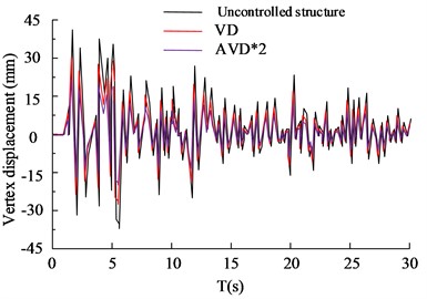
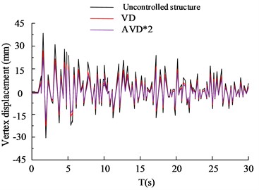
In the analysis of frequent earthquakes, refer to Table 3 for experimental parameters. According to the demand, two natural waves, Ken County (Ken County, KC) and Humbolt bay (Humbolt bay, HB) in 1952, were selected as experiments. In the analysis of frequent earthquakes, the peak acceleration is 110 cm/s2. The comparison of the structural vertex displacement is shown in Fig. 5.
Fig. 5Comparison of displacement of structural vertices
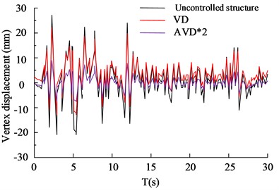
a) HB wave X-axis vertex displacement
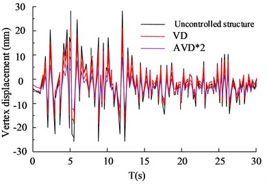
b) HB wave Y-axis vertex displacement
c) KC wave X-axis vertex displacement
d) KC wave Y-axis vertex displacement
Fig. 5(a) to 5(b) show the vertex displacement in the X and Y directions of the HB wave, respectively. From the data results, it can be seen that in frequent earthquake scenarios, VD structures have significant advantages in seismic performance compared to AVD*2 structures without control. The VD structure has a 27.65 % increase in seismic reduction compared to uncontrolled structures, while the AVD*2 structure has a 35.65 % increase in seismic reduction compared to uncontrolled structures. Fig. 5(c) and 5(d) show the displacement of KC wave vertices in the X and Y directions, respectively. According to the data results, VD and AVD*2 with structural design have significantly smaller displacement in the X and Y directions compared to uncontrolled structures. Compared with AVD * 2, the uncontrolled structure of VD has an increase of 24.35 % and 32.35 % in shock absorption rate, respectively. It can be seen that VD and AVD*2 optimize the displacement variation of the building structure in the X and Y directions, reduce the force by improving the viscous damper, shorten the movement of the X and Y axes, and significantly improve the safety of the building structure. The comparison of shear forces on structural floors is shown in Fig. 6.
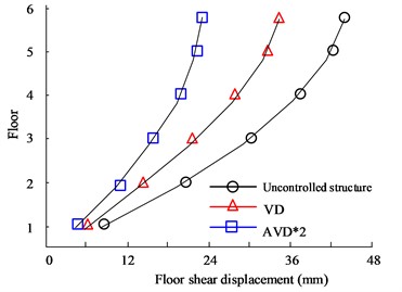
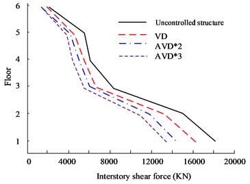
Fig. 6(a) to Fig. 6(b) are the HB wave X- and Y-direction shear force diagrams respectively. According to the curves in the figure, there are obvious differences in the seismic effects of the three types of seismic structure designs between floors. Among them, the AVD*2 structure with the best performance has the X-direction floor shear force controlled at 2186 KN on the first floor, while the VD structure is controlled at 2556 KN, and the Uncontrolled structure shear force is 2498 KN. In the Y-direction floor shear analysis, there are big differences between the three structures. The maximum floor shear force is still on the first floor. The maximum shear forces of no structure, VD and AVD*2 are 1956 KN, 1465 KN and 1265 KN respectively. Fig. 6(c) to Fig. 6(d) are the KC wave X- and Y-direction shear force diagrams respectively. It can be seen from the comparison of the curves that in the comparison of shear forces between floors in the Comparing the shear force, the AVD*2 structure with the smallest shear force control has a shear force value of 1503 KN, followed by VD with a shear force value of 1635 KN. The worst performance is the uncontrolled structure with a shear force value of 2623 KN. It can be seen that adopting structural design can significantly reduce the impact of seismic forces, mainly due to more effective seismic structural design, which offsets the forces from multiple directions of earthquakes. However, uncontrolled structures cannot counteract the forces, causing the structure to be affected by more forces and significantly reducing safety. Fig. 7 shows the displacement comparison results between structural floors.
Fig. 6Comparison of shear forces on structural floors
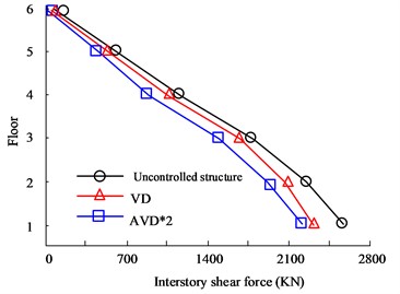
a) HB wave X-direction floor shear force
b) HB wave Y-direction floor shear force
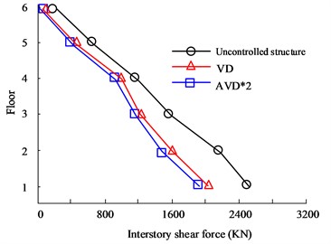
c) KC wave X-direction floor shear force
d) KC wave Y-direction floor shear force
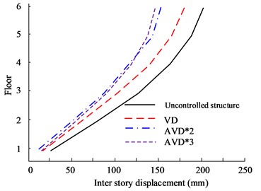
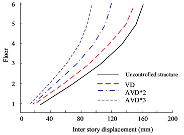
Fig. 7(a) to Fig. 7(b) are the X- and Y-direction displacement diagrams of the HB wave respectively. Judging from the data curve, as the number of floors continues to increase, the displacement between floors will continue to expand. When the floor reaches 6 floors, the maximum inter-floor displacement value will be obtained. Therefore, when comparing the inter-story displacement values of different structural designs on the 6th floor, in the comparison of X-direction displacement values, the largest displacement value is the uncontrolled structure, with a maximum value of 31.95 mm, followed by the VD structure, with a maximum value of 21.05 mm. The smallest inter-layer displacement is the AVD*2 structure, with a maximum value of 18.35 mm. In the comparison of Y-direction floor displacement values, the maximum displacement values of no structural design, VD, and AVD*2 on the 6th floor are 19.36 mm, 20.35 mm, and 10.68 mm respectively. It can be seen from the data structure that structural design is obviously better in seismic displacement control than uncontrolled structure. Fig. 7(c) to Fig. 7(d) are the KC wave X- and Y-direction displacement diagrams respectively. The test results are consistent with the HB test results. The AVD*2 structural design still has better seismic resistance in the X and Y directions. For example, in the X-direction floor displacement comparison, the maximum inter-story displacement value of the Uncontrolled structure is 43.35 mm, while the AVD*2. The maximum inter-story displacement value is 19.05 mm. It can be seen that AVD*2 structural design can significantly reduce the displacement effect of earthquakes on floors compared with no-structure design, and minimize earthquake hazards.
Fig. 7Comparison of displacement between structural floors
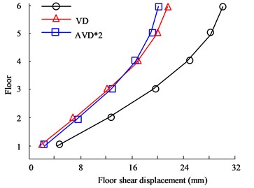
a) HB wave X-direction floor displacement
b) HB wave Y-direction floor displacement
c) KC wave X-direction floor displacement
d) KC wave Y-direction floor displacement
4.2. Analysis of rare earthquakes
The HB wave and KC wave in the experiment were still selected for the experiment, but the peak acceleration was increased to 510 cm/s2 to carry out 8-degree (0.3 g) rare earthquake experimental analysis. The remaining parameters are set according to the parameters of rare regions. The structural vertex displacement comparison is shown in Fig. 8.
Fig. 8(a) to Fig. 8(b) are the HB wave X- and Y-direction structural vertex displacement diagrams respectively. Judging from the data curve in the figure, the AVD*2 and AVD*3 structural designs can control the X-direction vertex displacement within the range of 50 mm, while VD can control the X-direction vertex displacement within the range of 100 mm. The maximum X-direction vertex displacement value of the structure-free design is 112 mm. In the comparison of the Y-direction structural apex displacement, the AVD*3 structural design performed best, followed by AVD*2, VD and no-structure design. Among them, the maximum displacement of the AVD*3 structure was controlled within the range of 30 mm, compared with 88 mm of the no-structure design. There is a significant improvement. Fig. 8(c) to Fig. 8(d) are the KC wave X and Y structure vertex displacement diagrams respectively. The test results are basically consistent with the HB wave test results. The AVD*3 structural design has better overall seismic resistance than the other two structural designs. The shock absorption rate of AVD*3 structural design is increased by 25.65 % compared to the structure-free design, the shock absorption rate of AVD*2 is increased by 21.56 % compared to the structure-free design, and the shock absorption rate of VD is increased by 12.35 % compared to the structure-free design. The comparison of structural floor shear forces is shown in Fig. 9.
Fig. 8Comparison of displacement of structural vertices
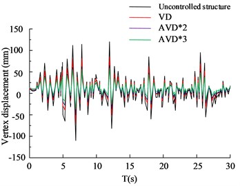
a) HB wave X-axis vertex displacement
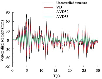
b) HB wave Y-axis vertex displacement
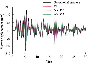
c) KC wave X-axis vertex displacement
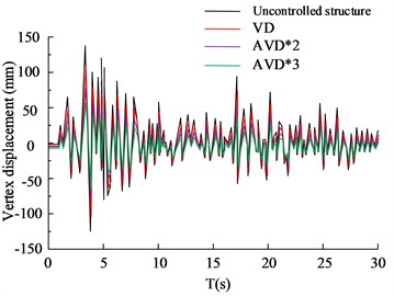
d) KC wave Y-axis vertex displacement
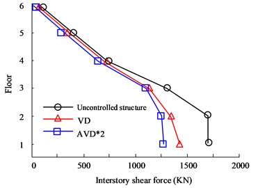
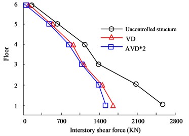
Fig. 9Comparison of shear forces on structural floors
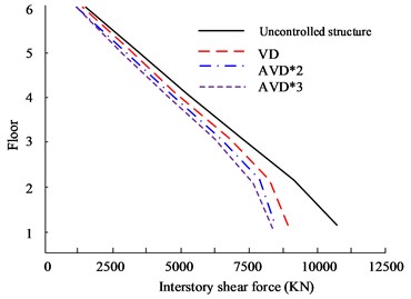
a) HB wave X-direction floor shear force
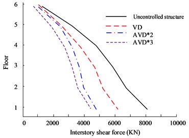
b) HB wave Y-direction floor shear force
c) KC wave X-direction floor shear force
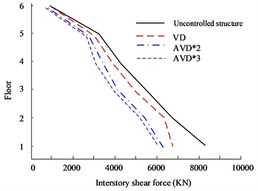
d) KC wave Y-direction floor shear force
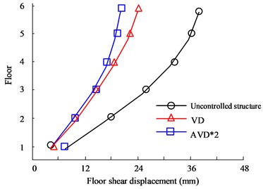
Fig. 9(a) to Fig. 9(b) are the HB wave X- and Y-direction shear force diagrams respectively. In rare earthquakes, the lower the floor, the more obvious the inter-floor shear force will be. Therefore, the first layer was selected for experimental analysis. In the shear force analysis between floors in the 8699 KN, while VD is 8865 KN. At the same time, in the Y-direction floor shear comparison, the AVD*3 structure still has the smallest inter-story shear value, which is 4486 KN, while the Uncontrolled structure is 8006 KN. Fig. 9(c) to Fig. 9(d) are the KC wave X- and Y-direction shear force diagrams respectively. AVD*2 and AVD*3 still have excellent shear force control effects. In the Y-direction floor shear force analysis, the maximum interstory shear force of the AVD*3 structure on the first floor is 6105 KN, while the maximum interstory shear force of AVD*2 is 6105 KN. The shear force is 6186 KN. Fig. 10 shows the comparison results of displacement between structural floors.
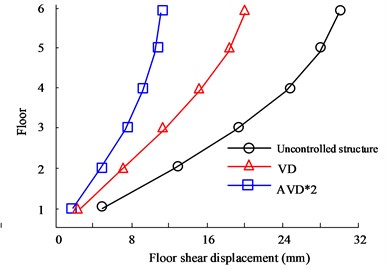
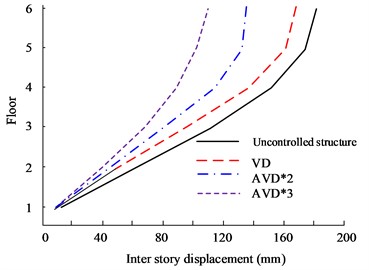
Fig. 10Comparison of displacement between structural floors
a) HB wave X-direction floor displacement
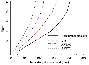
b) HB wave Y-direction floor displacement
c) KC wave X-direction floor displacement
d) KC wave Y-direction floor displacement
Fig. 10(a) to Fig. 10(b) are the X- and Y-direction interlayer displacement diagrams of HB wave respectively. According to the data, the maximum inter-story displacement value appears on the highest floor, and the 6th floor has the maximum displacement value. From a comprehensive comparison, it can be seen that AVD*3 and AVD*2 have the smallest inter-layer displacement values in the X and Y directions. In the comparison of X-direction inter-story displacement values, the maximum inter-story displacement values of AVD*3 and AVD*2 are 162 mm and 169 mm respectively, while the maximum inter-story displacement value of the Uncontrolled structure is 212 mm. Fig. 10(c) to Fig. 10(d) are the KC wave X- and Y-direction interlayer displacement diagrams respectively. The test results are consistent with the HB wave test results. AVD*3 still has better inter-layer displacement control effect.
5. Conclusions
The energy generated by earthquakes will cause serious damage to building structures, and effective seismic design of building structures is key. In order to solve the seismic problem of buildings, a displacement-based seismic design method is proposed. Firstly, research will be conducted on displacement seismic resistance and a displacement seismic resistance model will be constructed. At the same time, considering that traditional VD cannot effectively identify small displacement scenes, an optimized AVD is proposed and a seismic model is constructed based on the equivalent damping ratio expression. In the analysis of multiple earthquake resistance experiments, the shock absorption rate of AVD*2 is 35.65 % higher than that of the no-structure design, and is better than the VD structure, with the smallest vertex displacement value. In the floor shear comparison, HB wave Y-direction floor shear was selected for analysis. The maximum shear forces of VD and AVD*2 are 1465 KN and 1265 KN respectively. The overall seismic resistance of AVD*2 is better. In a rare earthquake experiment, the AVD*3 structural design increased the shock absorption rate by 25.65 % compared to the structure-free design, and the AVD*2 structure design increased the shock absorption rate by 21.56 % compared to the structure-less design. Compared with the VD and structure-less designs, there is a significant improvement. improvement. In the floor shear comparison, in the HB wave Y-direction shear analysis, the maximum interstory shear force on the first floor of the AVD*3 structure is 6105 KN, while the maximum interstory shear force of the AVD*2 structure is 6186 KN. Compared with the VD structure, the interlaminar shear is significantly smaller. Comparing the displacements between floors, in the comparison of the HB wave X-direction inter-story displacement, AVD*3 and AVD*2 have the smallest inter-story displacement values in the X and Y directions, which are 162 mm and 169 mm respectively, while the Uncontrolled structure is 212 mm. Through the above experiments, it can be seen that the technology proposed by the research institute has excellent application performance in both frequent and rare earthquakes, and is superior to similar technologies. It can be seen from this that the seismic design of buildings proposed in this research has excellent application effects in practical scenarios. However, there are also shortcomings in the research. The proposed seismic design did not consider the impact of amplification devices on dampers under horizontal displacement, and further research is needed in the future. In addition, research is mainly based on displacement methods for energy dissipation design of damping frames. In the future, capacity spectrum method and ductility coefficient method can be added for seismic design to improve the seismic performance of building structures.
References
-
P. Zakian and A. Kaveh, “Seismic design optimization of engineering structures: A comprehensive review,” Acta Mechanica, Vol. 234, No. 4, pp. 1305–1330, Dec. 2022, https://doi.org/10.1007/s00707-022-03470-6
-
D. Shahnazaryan and G. J. O. ’Reilly, “Integrating expected loss and collapse risk in performance-based seismic design of structures,” Bulletin of Earthquake Engineering, Vol. 19, No. 2, pp. 987–1025, Jan. 2021, https://doi.org/10.1007/s10518-020-01003-x
-
X. Guan M. Eeri, H. Burton M. Eeri, and M. Shokrabadi, “A database of seismic designs, nonlinear models, and seismic responses for steel moment-resisting frame buildings,” Earthquake Spectra, Vol. 37, No. 2, pp. 1199–1222, Nov. 2020, https://doi.org/10.1177/8755293020971209
-
A. Muttoni et al., “Deformation capacity evaluation for flat slab seismic design,” Bulletin of Earthquake Engineering, Vol. 20, No. 3, pp. 1619–1654, Jan. 2022, https://doi.org/10.1007/s10518-021-01302-x
-
C. Zhong and C. Christopoulos, “Self-centering seismic-resistant structures: historical overview and state-of-the-art,” Earthquake Spectra, Vol. 38, No. 2, pp. 1321–1356, Dec. 2021, https://doi.org/10.1177/87552930211057581
-
Z. Alam, L. Sun, C. Zhang, Z. Su, and B. Samali, “Experimental and numerical investigation on the complex behaviour of the localised seismic response in a multi-storey plan-asymmetric structure,” Structure and Infrastructure Engineering, Vol. 17, No. 1, pp. 86–102, Jan. 2021, https://doi.org/10.1080/15732479.2020.1730914
-
X. Hu, R. Zhang, X. Ren, C. Pan, X. Zhang, and H. Li, “Simplified design method for structure with viscous damper based on the specified damping distribution pattern,” Journal of Earthquake Engineering, Vol. 26, No. 3, pp. 1367–1387, Feb. 2022, https://doi.org/10.1080/13632469.2020.1719239
-
D. de Domenico and I. Hajirasouliha, “Multi-level performance-based design optimisation of steel frames with nonlinear viscous dampers,” Bulletin of Earthquake Engineering, Vol. 19, No. 12, pp. 5015–5049, Jun. 2021, https://doi.org/10.1007/s10518-021-01152-7
-
H. Akehashi and I. Takewaki, “Modeling of resilience based on categorized recovery scenario and improving resilience with viscous damper,” Japan Architectural Review, Vol. 5, No. 3, pp. 279–294, Jun. 2022, https://doi.org/10.1002/2475-8876.12273
-
M. Karami, H. E. Estekanchi, I. Hajirasouliha, and S. A. Mirfarhadi, “Value-based seismic performance optimization of steel frames equipped with viscous dampers,” Journal of Earthquake Engineering, Vol. 27, No. 14, pp. 4024–4050, Oct. 2023, https://doi.org/10.1080/13632469.2022.2155733
-
J. Humaidi, M. E. Sadiq, A. I. Abdulkareem, and I. M. Ibraheem, “Adaptive backstepping sliding mode control design for vibration suppression of earth-quaked building supported by magneto-rheological damper,” Journal of Low Frequency Noise, Vibration and Active Control, Vol. 41, No. 2, pp. 768–783, 2022, https://doi.org/10.1177/146134842110646
-
S. Jain, S. Pujari, and A. Laskar, “Investigation of one dimensional multi-layer periodic unit cell for structural base isolation,” Structures, Vol. 34, pp. 2151–2163, Dec. 2021, https://doi.org/10.1016/j.istruc.2021.08.093
-
C. Pany and G. Li, “Editorial: Application of periodic structure theory with finite element approach,” Frontiers in Mechanical Engineering, Vol. 9, No. 1, p. 11926, Apr. 2023, https://doi.org/10.3389/fmech.2023.1192657
-
C. Pany and S. Parthan, “Flutter analysis of periodically supported curved panels,” Journal of Sound and Vibration, Vol. 267, No. 2, pp. 267–278, Oct. 2003, https://doi.org/10.1016/s0022-460x(02)01493-1
-
G. Baltzopoulos, A. Grella, and I. Iervolino, “Seismic reliability implied by behavior‐factor‐based design,” Earthquake Engineering and Structural Dynamics, Vol. 50, No. 15, pp. 4076–4096, Sep. 2021, https://doi.org/10.1002/eqe.3546
-
G. J. O. ’Reilly, H. Yasumoto, Y. Suzuki, G. M. Calvi, and M. Nakashima, “Risk‐based seismic design of base‐isolated structures with single surface friction sliders,” Earthquake Engineering and Structural Dynamics, Vol. 51, No. 10, pp. 2378–2398, May 2022, https://doi.org/10.1002/eqe.3668
-
H.-H. Tsang, “Analytical design models for geotechnical seismic isolation systems,” Bulletin of Earthquake Engineering, Vol. 21, No. 8, pp. 3881–3904, Jul. 2022, https://doi.org/10.1007/s10518-022-01469-x
-
M. Guesmi, N. Belkheiri, and M. L. Guesmi, “Time history analysis of structures under multi-support excitation by state-space method,” Studies in Engineering and Exact Sciences, Vol. 5, No. 1, pp. 209–222, Jan. 2024, https://doi.org/10.54021/seesv5n1-012
-
R. Zhu, L. Song, T. Guo, and F. Mwangilwa, “Seismic analysis and design of SDOF elastoplastic structures with self-centering viscous-hysteretic devices,” Journal of Earthquake Engineering, Vol. 26, No. 9, pp. 4613–4634, Jul. 2022, https://doi.org/10.1080/13632469.2020.1835752
-
A. Q. Al-Dujaili, A. J. Humaidi, Z. T. Allawi, and M. E. Sadiq, “Earthquake hazard mitigation for uncertain building systems based on adaptive synergetic control,” Applied System Innovation, Vol. 6, No. 2, p. 34, Feb. 2023, https://doi.org/10.3390/asi6020034
-
T. Vu, H. Yeon, Y. Song, Y. Kim, and H. Lee, “Seismic response of an electrical switchboard with vibration absorbers during earthquake excitation,” Journal of Mechanical Science and Technology, Vol. 37, No. 7, pp. 3347–3355, Jun. 2023, https://doi.org/10.1007/s12206-023-0602-7
-
S. Leyva, N. Cruz-Pérez, J. Rodríguez-Martín, and J. C. Santamarta, “Classification of risks for landslides in slopes and hillsides of volcanic nature in Macaronesia and their application to the Canary Islands,” Geosciences, Vol. 13, No. 6, p. 155, May 2023, https://doi.org/10.3390/geosciences13060155
-
M. Böse, J. Andrews, R. Hartog, and C. Felizardo, “Performance and next-generation development of the finite-fault rupture detector (FinDer) within the United States West Coast ShakeAlert warning system,” Bulletin of the Seismological Society of America, Vol. 113, No. 2, pp. 648–663, Apr. 2023, https://doi.org/10.1785/0120220183
-
A. M. Usman and M. K. Abdullah, “An assessment of building energy consumption characteristics using analytical energy and carbon footprint assessment model,” Green and Low-Carbon Economy, Vol. 1, No. 1, pp. 28–40, Mar. 2023, https://doi.org/10.47852/bonviewglce3202545
About this article

This study is supported by Henan Science and Technology Project, Study on dynamic response of Bridge Foundation under tunnel construction in Loess area of Henan Province, No.: 232102240024 and Henan Province Higher Education Key Scientific Research Project Plan: Analysis of the Bidirectional Vibration Impact of a Subway Shield Underpassing an Existing National Railway Line Project, No.: 24B560027.
The datasets generated during and/or analyzed during the current study are available from the corresponding author on reasonable request.
Yingfei Guo made contributions to conceptualization, formal analysis, methodology, project administration, writing-original draft preparation and writing-review and editing. Sen Wang made contributions to made contributions to data curation, formal analysis, visualization and writing-review and editing. Shuyuan Zhang made contributions to made contributions to investigation, validation and writing-review and editing. All authors reviewed the manuscript.
The authors declare that they have no conflict of interest.
