Abstract
Chips must be reliably segmented and evacuated from the cutting zone for effective deep hole drilling. Drilling with low-frequency axial vibrations ensures these useful effects because cutting edges periodically leave the cutting zone. Useful tool vibrations can be maintained using a special self-vibratory drilling head. The drilling head has an elastic element and ensures the self-excitation of vibrations due to the regenerative effect. However, high damping in the cutting zone suppresses axial self-vibrations and renders such a drilling head inexpedient for industry. This study develops a novel system of adaptive control for the vibration drilling process. The control objective is to maintain a specified peak-to-peak (PTP) value of vibration displacements. Due to the in-process adaptation of the feedback gain, the control system supplies additional energy if vibrations are not self-excited and removes energy if the PTP vibration displacements are greater than the specified value. To test the workability of the system, an experimental setup was made. In the setup, the actuator force acts on an elastically fixed workpiece. The dynamic properties of the setup are equivalent to those of the vibration drilling head. The algorithm of feedback gain adaptation was implemented with a microcontroller. A number of experiments for different drilling regimes revealed that the control system successfully maintains the specified PTP value of displacements. The developed control system can be implemented on a vibration drilling head because only an accelerometer is required for control and the required actuator force is under 100 N.
Highlights
- A novel system of adaptive control for the vibration drilling process.
- The developed system aims to the objective of an arbitrary given non-zero vibration magnitude value, while the existing systems for controlling cutting vibrations can pursue only a vibration level of zero.
- Due to the in-process adaptation of the feedback gain, the control system supplies additional energy if vibrations are not self-excited and removes energy if the PTP vibration displacements are greater than the objective value.
- A number of experiments for different drilling regimes revealed that the control system successfully maintains the specified PTP value of displacements.
- In contrast to systems without control, the developed novel vibratory drilling system would work in a wide range of cutting conditions.
- The developed system can be implemented in a vibratory head for deep hole drilling in the aerospace and nuclear power industries and for drilling composite materials and multi-material stacks.
1. Introduction
Deep hole drilling is the technological operation used to produce shafts for different purposes, tube sheets for nuclear power plants, fuel injectors. One of the main problems limiting the performance of this technological process is the reliable evacuation of chips from the cutting zone. Usually, a continuous or fragmented chip is formed, and the evacuation of such chips is difficult, even with high-pressure coolant supplied in the cutting zone. A comprehensive review of fragmentation methods used in deep drilling has been done in [1].
Low-frequency vibration-assisted drilling (VAD) is one of the ways ensuring the segmentation and evacuation of chips from the cutting zone [2]. Additional low-frequency vibratory movement is transmitted to a drill in the feed direction, thereby causing cutting edges to periodically leave the cutting zone and enabling chip segmentation and evacuation. The cutting efficiency and surface quality can be improved due to the following special features of this method: 1) the small chip segments are easy to remove from the cutting zone, 2) the temperature in the cutting zone is reduced due to the improved lubrication of the cutting edges [3], 3) the average forces and the machine tool power consumption are both reduced [4], and 4) the hole wall roughness is reduced [5], [6]. The comprehensive experimental study [2] has shown that low-frequency vibrations could increase tool life due to lower temperatures in the cutting zone. VAD can be used to avoid the described problem of deep hole drilling in the aerospace industry, nuclear power industry and others. Additionally, VAD can improve the hole quality after drilling composites and multi-material stacks.
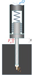
By now, tool holders for VAD with a kinematic working principle have found industrial applications [7]. In those tool holders, the tool’s axial movement is achieved using a wave roller path of thrust bearings. Another way to generate useful axial tool vibrations during drilling is to use a special self-vibratory drilling head (SVDH, see Fig. 1) proposed by Gouskov [9]. The axial stiffness of the elastic element is chosen to be several times less than the stiffness of the machine tool, workpiece, fixture and cutting tool [10]. In addition, the elastic element has significant rigidity in twisting. Thus, the dynamic system “vibratory head – tool” is essentially a 1-DOF oscillator that can vibrate in the direction of the rotation axis. For certain combinations of the spindle speed and elastic element stiffness, self-excited vibrations (chatter) can arise due to a regenerative effect [11]. When the vibration amplitude reaches a certain value, chips start segmenting.
Fig. 1Design of self-vibratory drilling head [8]
![Design of self-vibratory drilling head [8]](https://static-01.extrica.com/articles/23916/23916-img1.jpg)
a) Photograph of an SVDH with an integrated elastic element
![Design of self-vibratory drilling head [8]](https://static-01.extrica.com/articles/23916/23916-img2.jpg)
b) An elastic element with openings
In [12], Tichkiewitch et al. have investigated the dynamic properties of drilling with SVDH and built a stability lobe diagram; they obtained simulated and experimental time histories of vibration displacements. One of the observations made by the authors is that the amplitude of self-excited vibrations could be high enough to reduce tool life. Paris et al. [10] built stability lobes of the system according to the elastic element’s stiffness and spindle speed. Gouskov et al. [13] have analyzed the influence of parasite torsional self-excited vibrations on the generation of useful axial vibrations.
In [14], Guibert et al. have developed a model of axial forces during VAD where the cutting edge is separated into a primary cutting edge and a chisel edge. Guibert et al. [15] have identified parameters of the empirical model of the cutting forces. According to this paper, more than 50 % of the axial cutting force is generated by the chisel edge (ploughing effect). Paris et al. [16] have investigated VAD dynamics taking into account the ploughing effect. Forestier et al. [17] have developed a dynamic model of the vibration drilling process, taking into account the dynamic properties of the spindle, the SVDH and the tool. Kiselev et al. [18] have developed a three-dimensional vibration drilling dynamic model whose special feature is to use the depth buffer algorithm to model the machined surface’s three-dimensional geometry.
VAD with an SVDH has significant drawbacks impeding industrial application. First, it would work only if the elastic element stiffness and the spindle speed meet certain conditions. Fig. 2 shows that for a given elastic element stiffness the vibrational drilling is provided only for a narrow band of spindle speed values. Thus, to achieve vibrational drilling for a wide range of operating conditions, a set of replaceable elastic elements with different stiffnesses, each for specific spindle speed, should be used. Second, a high dissipation of energy at the chisel edge prevents self-excited vibrations. To study this effect, Moraru [19] has conducted an experiment of drilling a workpiece with a pilot hole with a diameter smaller than the main hole but greater than the chisel edge size. At the beginning of the drilling, the chisel edge did not take part in the cutting process, so self-vibrations were excited in the system. However, as the drill went deeper, the pilot hole ended and the chisel edge started interacting with the workpiece material, thereby suppressing self-vibrations. Therefore, useful chatter was suppressed by damping at the chisel edge. This phenomenon happens because ploughing, not cutting, takes place at the chisel edge due to low circumferential velocities. Third, energy dissipation in the cutting region increases as the tool wears [20]. Thus, if self-vibrations are present with a sharpened cutting tool, this does not mean that useful self-vibrations will occur with a worn tool.
Fig. 2Stability lobes [10]. SVDH stiffness – stiffness of the SVDH’s elastic element
![Stability lobes [10]. SVDH stiffness – stiffness of the SVDH’s elastic element](https://static-01.extrica.com/articles/23916/23916-img3.jpg)
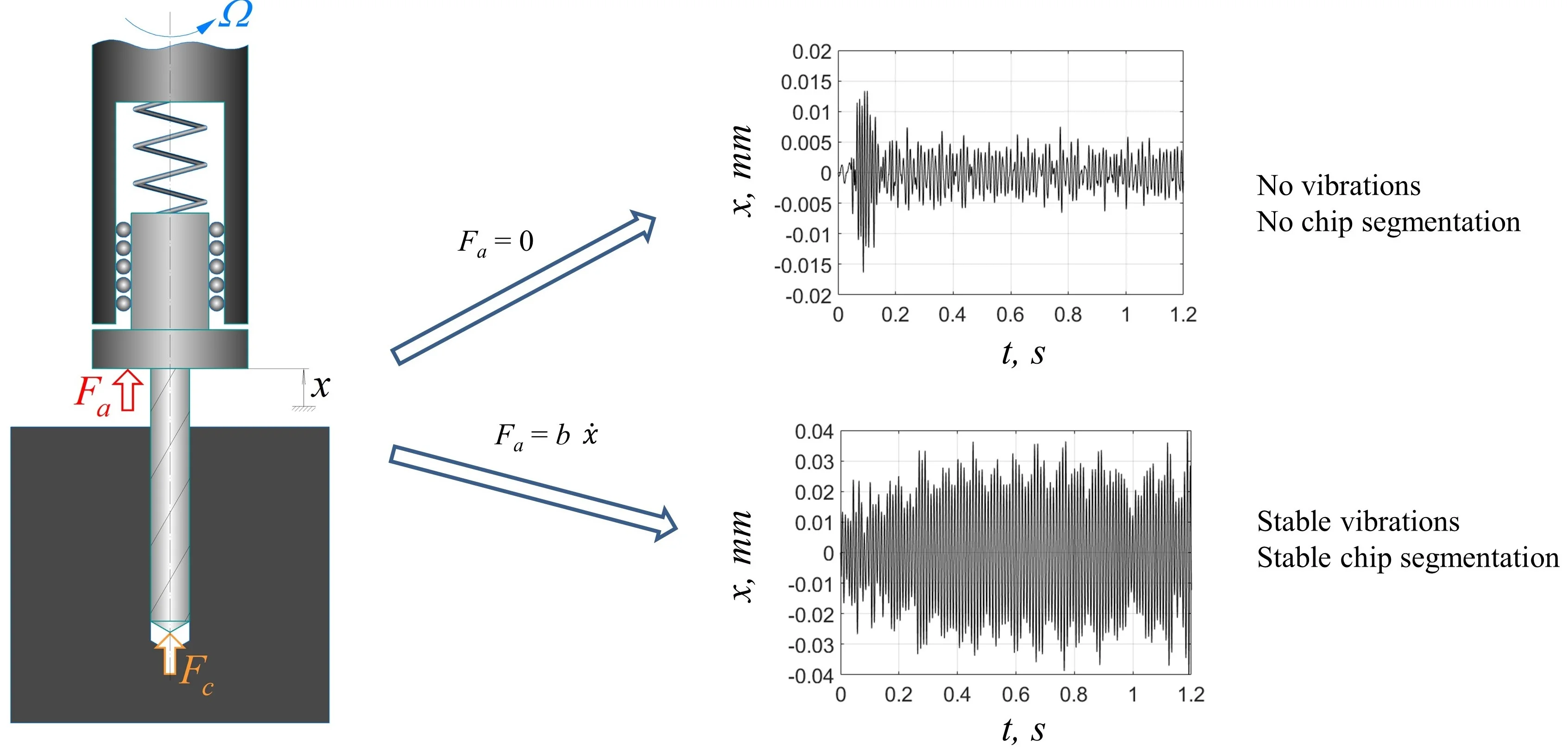
The limitations of the drilling process with an SVDH described above can be overcome by introducing a control force to the system. The control will add energy to the vibration system if the vibration amplitudes are not large enough to segment chips and will remove the energy if the vibration amplitudes are excessive. Thus, chip segmentation is enabled in a wide range of process parameters for different drill diameters and workpiece materials. It therefore makes sense to consider a system with a scheme presented in Fig. 3. The system includes a drill, a moving (vibrating) part and a stationary part of the vibration drilling head (VDH), an elastic element, and a workpiece. Cutting force Fc and control force Fa are applied to the system.
Fig. 3Scheme of vibration drilling with control: Fa – control force, Fc – axial cutting force, x – coordinate of the moving part of VDH, Ω – spindle speed
Batzer et al. [21] have investigated the dynamic properties of VAD with control action prescribed as an external harmonic excitation. Although this excitation method allows additional energy to be supplied to the vibration drilling system, the method has inadequate control over the generated vibration levels. In addition, the system cannot automatically tune excitation amplitude and frequency if the energy dissipation in the cutting zone changes.
Thus, it makes sense to try a control system with feedback to maintain the specified vibration amplitude of VDH’s moving part. The problem of delivering the control action to the rotating drilling head has been already solved in the patent [22]. Therefore, the current paper focuses on the feedback control algorithm rather than its technical implementation.
There are many algorithms of active control for cutting dynamics [23]-[25]; however, they have been designed to suppress chatter instead of maintaining it at a required level. The developed algorithms therefore cannot be used in vibration cutting.
To fill the lack of control systems for VAD, Gouskov et al. have developed a control algorithm [9], [26] using adaptation of feedback gain by cutting continuity index and a control algorithm [27] with a mixed adaptation of feedback gain based on the values of peak-to-peak (PTP) displacements and cutting continuity index. To calculate the cutting continuity index, the cutting force in the cutting zone must be measured. These algorithms were not verified experimentally because installing a force sensor on a tool tip is complicated, and the noise level of cutting forces measurements is high.
This paper presents a novel adaptive control system that maintains target PTP displacement in a wide range of process parameters. This system aims to the objective of an arbitrary given non-zero vibration magnitude value, while the existing systems for controlling cutting vibrations can pursue only a vibration level of zero. The control action is set proportional to the vibrational velocity. A controller adjusts the feedback gain to supply energy to the system if the vibrations are not self-excited and to remove energy if the vibration amplitudes are excessive. Vibration levels are monitored and automatic feedback gain is adjusted directly during cutting. The proposed control system extracts benefits from the two approaches for low-frequency vibratory drilling implementation: SVDH [8] and using a drilling head with an actuator [22].
The presented control algorithm has been developed from the previously published control algorithms [26], [27]. A comprehensive simulation study of its properties has been presented in [28], and some related topics have been studied in [29]-[31]. The paper [30] has shown that a vibratory drilling system with the developed control algorithm ensures the required PTP displacement for a wide range of operating conditions, thereby overcoming the necessity of using a set of elastic elements with different stiffnesses. Besides, the issues of unknown and unstable energy dissipation can be smoothed out, if not eliminated, by adding energy to the control action.
For brevity, the current paper focuses only on experimental study.
The rest of the paper is organized as follows. Section 2 describes the adaptive control system comprising both hardware and software. Section 3 describes the experimental setup. Section 4 presents the experimental results, and Section 5 presents the conclusion.
2. Adaptive control system
This section is divided into several subsections. To better understand the principles underpinning the control system, it makes sense to define its part in its interactions with the other elements of the vibration drilling system; this is presented in Subsection 2.1. Subsection 2.2 describes the objectives of the control system. Subsections 2.3 and 2.4 present the control algorithm, and Subsection 2.5 shows the general control system layout as well as the hardware layout.
2.1. Closed-loop dynamic system structure
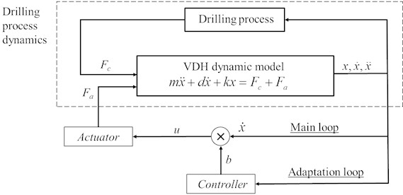
Fig. 4 shows the structure of the closed-loop dynamic system “cutting – VDH – control system”. The interactions between the main elements of the system are described below. For brevity, the presented block diagram does not show a measurement system, an amplifier, a signal filtration block, and some other elements.
The displacement x of the moving part of the VDH is determined by the cutting force Fc, actuator force Fa, mass and stiffness of the elastic element and damping factor. The cutting force Fc is generated in drilling process. Generally, tool vibrations cause an alternating value of Fc. It should be noted that Fc is a function of not only the vibration displacements of the cutting edges, but also the surface obtained during previous passes.
The control system determines the actuator force Fa as follows. The measured signals are supplied to two control loops: the main loop and the adaptation loop. In the main loop, the vibration velocity signal is multiplied by the feedback gain b. The controller sets the gain b in the adaptation loop according to the algorithm described in Subsection 2.3. If b>0, the vibrations are amplified; if b<0, the vibrations are damped. The product of b and ˙x, the control output u, is supplied to the actuator generating the force Fa.
The described system thus considers the influence of vibration on cutting forces and vice versa. The adaptation of the coefficient b allows the adjustment of the amplitude of the vibration process.
Fig. 4Block diagram of the closed-loop system “cutting – VDH – control system”
2.2. Control objective
Evidently, vibration amplitudes over a certain threshold value cause chip segmentation. This threshold is determined by the feed per cutting edge and the ratio of vibration frequency to the tooth pass frequency [2], [32]; it thus can be either calculated or found experimentally. If the proper amplitude is known and the control system maintains it, then chip segmentation is ensured. As the mean value of vibration displacement is generally not zero, it would be easier to consider not the displacement amplitude but the PTP displacement value. This is defined as the difference between the maximum and minimum values of the x coordinate for the considered time interval.
It should be noted that the alternative variant of control based on the cutting continuity coefficient [9], [27] is promising. However, as mentioned in the Introduction, this is currently unfeasible.
2.3. Control strategy
This paper proposes a new adaptive control strategy of the vibration process. Although the system was developed for the vibration drilling process, it could be applied to any monoharmonic vibration process.
The assumptions for developing the control system are as follows:
1) The hardware part of the control system and the actuator do not make any serious changes in the phase of the signal u (Fig. 4). This assumption is elaborated upon in the conclusion.
2) The steady-state PTP displacement value will grow with increased values of the feedback gain b, and it will recede if the feedback gain decreases. In other words, the coefficient b can be considered as negative damping.
3) System vibrations are close to monoharmonic. This assumption is proved by the experimental results of this study.
4) The computation time of the controller (additional delay) is negligible compared to the VDH vibration period; it does not lower the control quality.
The control objective is to maintain the target value of the vibration displacement PTP value A0. This requirement is met by the following heuristic adaptation algorithm:
where bc is dimensionless feedback gain; c1 and c2 are dimensionless adaptation law constants; A is the PTP displacement value, mm; A0 is the target value of A, mm; and Tb is the time constant of the adaptation law, s. The first addend of Eq. (1) ensures the growth of bc, if A<A0, and the reduction of bc, if A>A0. The second addend is introduced to stabilize the closed-loop system. It should be noted that bc differs from b shown in Fig. 4.
The inequality (2) is introduced because the practical voltage levels in the electronic circuits are limited. For normalization purposes, the maximum value of bc is set to 1. In this study, the control system is organized in such a way that bc=1 corresponds to 5 V at the controller output, and bc= –1 corresponds to 0 V.
Unfortunately, testing revealed that the direct application of Eq. (1) was not useful. First, the process of settling A to the target value of A0 could last a long time – at worst, longer than the drilling process itself. This may cause the drill to jam, as PTP displacements would not be sufficiently high to fragment chips. Second, the vibration drilling process is characterized by the super-fast dynamics of the change of integral process characteristics. According to our experience, the PTP vibration displacements often grow from zero to a steady-state value greater than the target value A0 and back in around 0.1…0.2 s. This phenomenon is related to encountering hard particles in the cutting zone plus the subcritical character of the bifurcation that manifests in leaping fluctuations of the vibration amplitude. The smooth change of bc prescribed by Eq. (1) cannot react fast enough to these fluctuations. Low values of c1 and c2 do not allow the PTP value A to return to the target value A0 in the required time in case of large deviations, while large values of c1 and c2 cause instability in the closed-loop system “cutting-VDH-control system”.
Thus, Eq. (1) was modified as follows:
where g1 and g2 are dimensionless parameters, g1,2< 1. These parameters determine the width of the PTP displacement range within which the equality b=bc is used.
Therefore, when the tool starts cutting, A is around zero, and the control system sets the maximum feedback gain b to 1. Then, as the system approaches A0, the feedback ratio is set to bc. Using the value bc determined by Eq. (1) allows the automatic regulation of the vibration process in case of a slight deviation of the PTP displacement A from its target value A0. If the PTP displacement A is too far from A0, Eq. (3) sets b= ±1 depending on the deviation sign.
The value of the coefficient b can only be in a discrete set of values determined by the bitness of the digital-to-analog converter. For brevity, this issue is not considered in this study.
2.4. Calculating peak-to-peak displacements
The PTP vibration displacement A is an important term of Eqs. (1-3). This subsection describes the calculation method. By definition, the PTP displacement can be calculated as follows:
where TA is the duration of the considered time interval, s; tf is the end of the considered time interval, s.
In practice, calculations according to Eq. (4) require time-consuming operations of finding the maximum and minimum values of the array, which does not allow the implementation of the control action on time.
Therefore, this study uses another expression whose brief derivation is given in Appendix:
where A is the PTP displacement estimate, mm; ωc is the chatter frequency, rad/s. For smoothing, signal A goes through a digital low-pass filter.
Eq. (5) is valid because the vibration process is close to monoharmonic. However, only acceleration ¨x is measured directly in Eq. (5); velocity is determined as integrated acceleration.
Chatter frequency ωc in Eq. (5) is determined as follows. All time points where the vibration velocity signal crosses zero from negative to positive are determined. The distance between the last two points is the estimate of the vibration period Tc. This value is used to calculate chatter frequency:
where ωc is the chatter frequency estimate, rad/s; Tc is the vibration period, s. The signal ωc goes through a digital low-pass frequency for smoothing.
2.5. Description of the control system operation
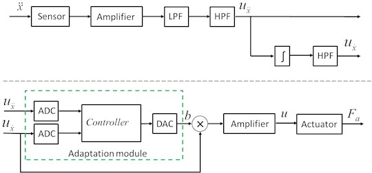
Fig. 5 displays the hardware of the control system. Vibration velocities are calculated by integrating vibration accelerations. Based on both signals, the controller calculates b, which is then used as the velocity feedback gain.
Fig. 5Diagram of the hardware part of the control system. LPF – low-pass filter, HPF – high-pass filter, ux¨ – vibration acceleration signal, ux˙ – vibration velocity signal, ADC – analog-to-digital converter, DAC – digital-to-analog converter
The controller algorithm is as follows:
1) Initialization of variables: ωc is equal to the eigenfrequency of the VDH, A and bc are 0, and b is 1.
2) Time step j.
3) Input the current values of vibration acceleration ¨x and vibration velocity ˙x.
4) If ˙xj>0,˙xj-1<0, adjust ωc, using Eq. (6) and the low-pass filter.
5) Calculate PTP displacement using Eq. (5) and the low-pass filter.
6) Calculate bc using the equation derived from Eq. (1):
where Δt is the time step, s.
7) Limit bc according to Eq. (2).
8) Calculate b using Eq. (3).
9) Set a new value of b at the controller output.
10) j=j+1, go to step 2.
3. Experimental setup
To validate the developed control system, an experimental setup, Fig. 6, was used. The setup differs from the widely used vibration drilling scheme. The drill is rigidly fixed in the machine spindle that executes feed motion with a constant velocity. The workpiece is fixed elastically, and it can vibrate in the direction of the drill axis. The actuator force Fa maintains the target PTP value of vibration displacements of the workpiece. The dynamic properties of this system are equivalent to that of the system shown in Fig. 3.
Fig. 6Scheme of the experimental setup
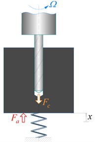
Table 1Parameters of the experimental setup for vibration drilling
1st eigenfrequency of the elastic fixture p | 70.86 Hz |
2nd eigenfrequency of the elastic fixture | 458.1 Hz |
Total stiffness of deformable plates k | 2050 N/mm |
Spindle speed Ω | 2000…5000 rpm |
Number of flutes z | 2 |
Frequency ratio 60·p/(z·Ω) | 1.063…0.425 |
Feed | 0.02 mm/cutting edge |
Workpiece material | Aluminum alloy |
Drill | HSS Super Ø 6 mm L 139/91 mm |
Actuator (vibration exciter) | Brüel & Kjær Type 4826 |
Amplifier | Brüel & Kjær Type 2721 |
Accelerometer | Kistler Type 8704B100M1 |
Actuator force sensor | Brüel & Kjær Type 8230-002 |
Controller | Arduino Uno |
Time to calculate feedback gain by the controller b (approx.) | 300 µs |
Table 2Control algorithm parameters
c1, c2 | 1.0 |
Tb | 0.07 s (around five periods of free vibrations) |
g1, g2 | 0.2 |
A0 | 0.06 mm |
Fig. 7(a) shows the experimental setup. The workpiece is attached to the movable part of the elastic fixture, and deformable plates perform the function of the elastic element (spring) in Fig. 6. The workpiece and the movable part of the elastic fixture can vibrate mostly in one direction. The accelerometer signal goes to the feedback loop where the actuator force Fa is determined; Fa is applied to the system via the actuator rod. Fig. 7(b) shows the electromagnetic actuator, and Fig. 7(c) shows the control system circuit. The listed elements of the experimental setup interact according to the control system diagram shown in Fig. 4. Table 1 shows the main parameters of the experimental setup; Table 2 shows the parameters of the control algorithm. The target PTP displacement value A0 was chosen based on relations [2], [32] determining the minimum PTP value required for chip segmentation under a given feed per cutting edge and frequency ratio 60p/(zΩ), Table 2.
Fig. 7Experimental setup for vibration drilling with control
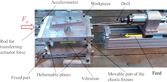
a) Vibration drilling setup
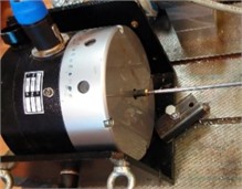
b) Actuator
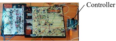
c) Control system
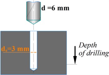
For investigation purposes, aside from full hole drilling, experiments on drilling with a pilot hole of a 3 mm diameter, Fig. 8, were conducted. Here, the central part of the drill does not transfer load during the whole drilling process, and all interaction occurs at the drill periphery. The results of the experiments for both drilling options (with and without the pilot hole) with and without control are shown in subsequent sections. Additional experiments measured axial force during conventional drilling.
The time histories of vibration displacements were obtained using the double integration of measured vibrational accelerations. High-frequency measurement noises were filtered out.
Fig. 8Drilling with a pilot hole
4. Experimental results
4.1. Results of measuring axial force during conventional drilling
To study the influence of the chisel edge on the cutting force, drilling without vibrations was performed. In these tests, the workpiece was rigidly fixed to a Kistler Type 9257B dynamometer instead of a vibration drilling setup (Fig. 7). Table 3 shows the results of axial force measurements for different feed values for drilling with and without a pilot hole. The spindle speed was 3600 rpm. Table 3 shows that around 80 % of the axial force was produced at the chisel edge.
Table 3Average measured axial forces for conventional drilling
Feed, mm / cutting edge | Axial forces for drilling with pilot hole (d0=3 mm) Fx, N | Axial forces for full hole drilling Fx, N | Contribution of the chisel edge in the axial force, % |
0.02 | 32.8 | 158.0 | 79.2 |
0.03 | 41.6 | 206.5 | 79.9 |
0.04 | 50.3 | 284.5 | 82.3 |
0.05 | 59.2 | 362.4 | 83.7 |
4.2. Drilling with a pilot hole (d0= 3 mm)
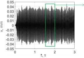
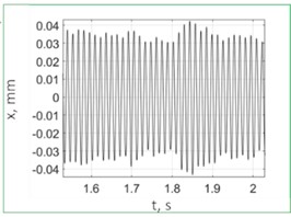
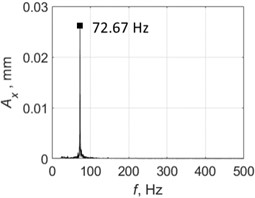
Fig. 9 shows the test results for drilling without control; spindle speed was Ω= 2500 rpm. PTP displacements reached significant values of about 0.6 mm, and the vibration character was almost monoharmonic. The vibration frequency of 72.38 Hz was slightly higher than the eigenfrequency of the elastic system (70.86 Hz). Fig. 10 shows the results for drilling with control. The vibration frequency did not practically change, and the PTP displacement value was around the target value of 0.06 mm. Here, the control system limited the self-excited vibrations of the system by the target level. The presented spectra confirm the monoharmonic signal character assumption that was made to derive Eq. (5).
Fig. 9Vibrations for drilling with a pilot hole without control, spindle speed 2500 rpm
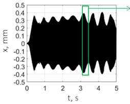
a) Vibration displacements
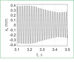
b) Vibration displacements (enlarged)
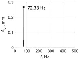
c) Spectrum
Fig. 10Vibrations for drilling with a pilot hole with control, spindle speed 2500 rpm
a) Vibration displacements
b) Vibration displacements (enlarged)
c) Spectrum
Table 4Time histories of vibration displacements for drilling with a pilot hole
Without control | With control | |
Ω=2000 rpm | 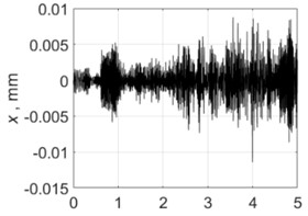 | 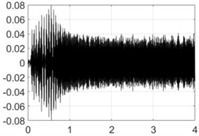 |
Ω=3000 rpm | 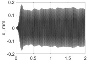 | 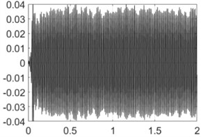 |
Ω=3500 rpm | 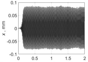 | 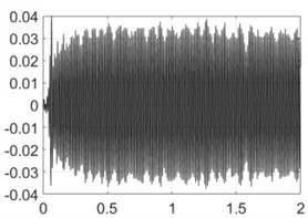 |
Ω=4000 rpm | 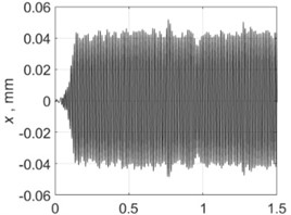 | 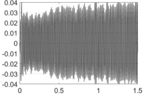 |
Ω=4500 rpm | 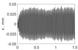 | 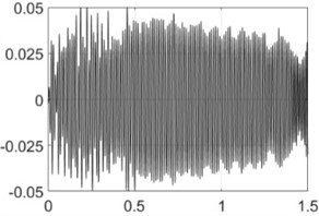 |
Ω=5000 rpm |  | 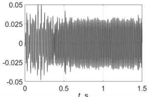 |
Table 4 shows all experimental results when drilling with a pilot hole. For Ω= 2000 rpm, there was no self-excitation of vibrations without control, but turning on the control provided the excitation of vibrations at the required level. In contrast, the control system limited vibrations for Ω= 3000, 3500 and 4000 rpm. For Ω= 4500 and 5000 rpm, the control system did not significantly change the characteristics of the vibration process because its characteristics were already close to the required values without any control.
Fig. 11 generalizes the conducted experiments in the form of a Poincare map. It was built as follows. The X-axis represents spindle speed Ω. For a given value of Ω, vibrations were measured, and vibration displacement peaks were determined on the steady-state time interval. These peaks were plotted on a vertical line corresponding to the given Ω on the Poincare map.
The diagram comparison shows that introducing control ensured vibrations with PTP displacements close to the target value 0.06 mm for the whole investigated spindle speed range. Thus, in contrast to vibratory drilling without control [8], [18], with the developed novel control system, the vibration amplitude is almost not sensitive to the spindle speed.
Fig. 11Poincare maps of vibration displacements when drilling with a pilot hole
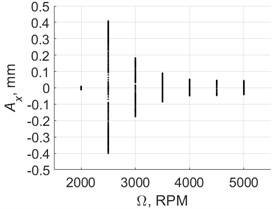
a) Control off
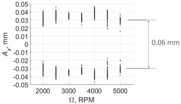
b) Control on
Fig. 12Vibrations for full hole drilling without control with a spindle speed of 5000 rpm
a) Vibration displacements
b) Spectrum
Fig. 13Vibrations for full hole drilling with control with a spindle speed of 5000 rpm
a) Vibration
b) Vibration (enlarged)
c) Spectrum
Table 5Time histories of vibration displacements for full hole drilling
Without control | With control | |
Ω=2000 rpm | 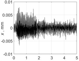 | 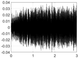 |
Ω=2500 rpm | 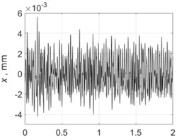 | 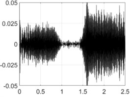 |
Ω=3000 rpm | 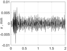 | 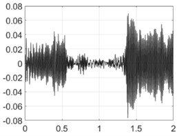 |
Ω=3500 rpm | 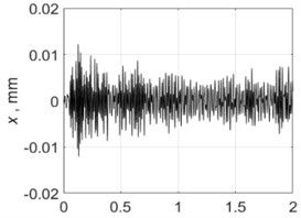 | 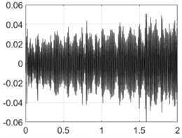 |
Ω=4000 rpm | 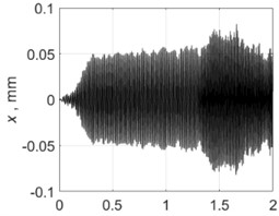 | 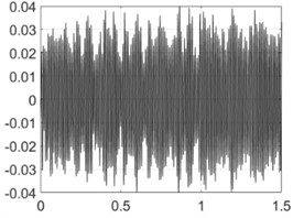 |
Ω=4500 rpm | 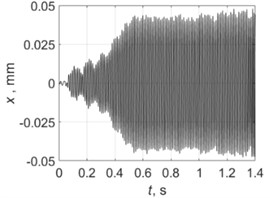 | 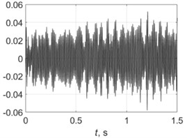 |
4.3. Full hole drilling
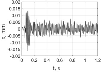
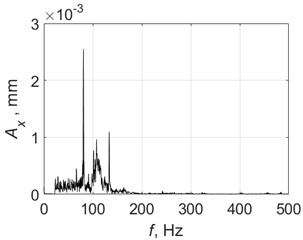
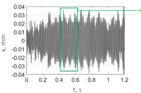
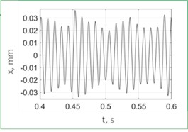
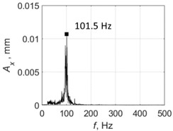
Fig. 12 shows example measurements without control. The PTP displacement was much less than the target value of 0.06 mm and even the feed value of 0.02 mm/cutting edge. Vibrations were polyharmonic. Results when drilling with control are shown in Fig. 13. Here, the control ensures the vibration of the system with a PTP displacement value close to the target value 0.06 mm; the control system also enables chip segmentation. The spectrum (Fig. 13(c)) shows that the process is not strictly monoharmonic, but there is a single distinct peak around 101.5 Hz.
Table 5 shows all experimental results for full hole drilling. For Ω= 4000 and 4500 rpm, regenerative chatter was self-excited and PTP displacements were greater than the target values. With control, the PTP vibration displacements were limited to the target values. For other process regimes, Ω= 2000, 2500, 3000 and 3500 rpm, there was no self-excitation, and vibrations were low without control, so control enabled the excitation of vibrations to the required levels.
The experimental results are generalized as Poincare maps in Fig. 14. By comparing the results for this case with the results for drilling with a pilot hole, Fig. 11, it can be concluded that the chisel edge has a fundamental influence on energy dissipation in the system. When the chisel edge did not take part in drilling, the self-excitation of vibrations without control occurred for all regimes except one (Ω= 2000 rpm). For full hole drilling, there was no pilot hole and the chisel edge was not excluded from the cutting process, which caused an inverse effect: The excitation of vibration with PTP displacement close to the target value of 0.06 mm took place for two regimes only. For other regimes, there were no notable vibrations.
The second effect of the drill chisel edge was a significant fluctuations of the vibration magnitudes for all regimes, even with control (Fig. 14(b)). Furthermore, for two regimes (Ω= 2500 and 3000 rpm), the control system did not ensure a stable vibration process; one time interval demonstrated a temporary suppression of vibrations. This interval indicates the significant non-stationary nature of the characteristics of energy dissipation in the chisel edge and indicates the need to improve the control system, which is discussed in the conclusion.
Fig. 14Poincare maps of vibration displacements, for full hole drilling
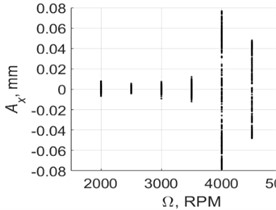
a) Without control
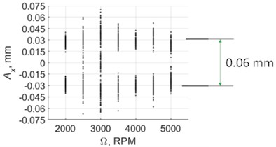
b) With control
4.4. Actuator force measurements
Fig. 15 presents the results of measuring the actuator force Fa. Force was measured using a sensor installed in the rod between the actuator (Fig. 7(b)) and the movable part of the experimental setup for vibration drilling (Fig. 7(a)). The cases of drilling with a pilot hole (Fig. 15(а)) and full hole drilling (Fig. 15(b)) were considered. Fig. 15 indicates that the chisel edge caused a significant (approximately four times) increase of the maximum actuator force. This conclusion agrees with the increased axial force of full hole conventional drilling compared to the drilling with a pilot hole observed in Subsection 4.1.
Fig. 15Poincare maps of the actuator force with control on
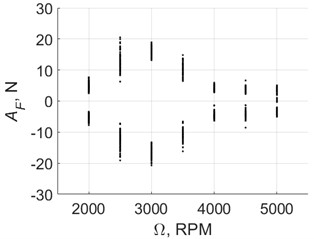
a) Full hole drilling
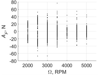
b) Drilling with a pilot hole
4.5. Repeatability of the experimental results
An important observation made by the authors was that the vibration levels obtained without control in different tests under the same test conditions were different. When drilling with a pilot hole (when the chisel edge does not contribute to the process), the difference was in an insignificant fluctuation of vibration amplitude and frequency. When full hole drilling (when the chisel edge contributes to the cutting), there was a qualitative difference between vibrations obtained for the same process regimes. The self-excitation of vibrations was observed for only some experiments. A negative influence of tool wear on the self-excitation of vibrations was observed. The results for Ω= 4000 and 4500 rpm (Table 5 (left pictures)) were obtained on a practically new drill with sharp edges. For the second series of tests, there was no self-excitation of vibrations. Replacing the drill with a new one allowed self-vibrations to be generated again, but only once. This observation is consistent with a known dependence between tool wear and vibration energy dissipation in the cutting zone [20]. With control, this phenomenon was not observed: the required level of vibrations was maintained for both the new and the worn drill.
Tables 6 and 7 show the full reports on the excitation of vibrations and the repeatability of the results. When the chisel edge did not transfer force, as shown in Table 6, there was a qualitative repeatability of results from test to test. When the chisel edge transferred load, as shown in Table 7, the qualitative repeatability of results was only observed with control. If the control was off and the chisel edge contributed to cutting, there was no repeatability of the self-excitation of vibrations.
Table 6Summary of information on the excitation of vibrations and the repeatability of results for drilling with a pilot hole (d0= 3 mm)
Ω, rpm | Without control | With control | ||
Excitation of vibrations | Repeatability of results | Excitation of vibrations | Repeatability of results | |
2000 | × | ✓ | ✓ | ✓ |
2500 | ✓ | ✓ | ✓ | ✓ |
3000 | ✓ | ✓ | ✓ | ✓ |
3500 | ✓ | ✓ | ✓ | ✓ |
4000 | ✓ | ✓ | ✓ | ✓ |
4500 | ✓ | ✓ | ✓ | ✓ |
5000 | ✓ | ✓ | ✓ | ✓ |
Table 7Summary of information on the excitation of vibrations and the repeatability of results for full hole drilling
Ω, rpm | Without control | With control | ||
Excitation of vibrations | Repeatability of results | Excitation of vibrations | Repeatability of results | |
2000 | × | ✓ | ✓ | ✓ |
2500 | × | ✓ | ✓ | ✓ |
3000 | × | ✓ | ✓ | ✓ |
3500 | × | ✓ | ✓ | ✓ |
4000 | ✓ | × | ✓ | ✓ |
4500 | ✓ | × | ✓ | ✓ |
5000 | × | ✓ | ✓ | ✓ |
4.6. Vibration frequency
Table 8 presents the frequency values corresponding to peaks of the vibration displacement spectra. The case of drilling with control on was considered. With control off, the results were qualitatively identical.
Table 8The frequencies of peaks at the vibration displacement spectra
Ω, rpm | Drilling with a pilot hole | Full hole drilling |
2000 | 88.7 Hz | 104.7 Hz |
2500 | 72.7 Hz | 106.6 Hz |
3000 | 80.5 Hz | 91.9 Hz |
3500 | 85.5 Hz | 97.3 Hz |
4000 | 85.1 Hz | 100.3 Hz |
4500 | 82.4 Hz | 102.2 Hz |
5000 | 84.3 Hz | 101.5 Hz |
Let us consider the cases of drilling with a pilot hole and full hole drilling. It can be seen that the vibration frequency for drilling with a pilot hole is greater than the eigenfrequency of the elastic fixture, as shown in Table 1. This increased frequency is related to the influence of the stiffness of the process, and this is consistent with the established fact that the chatter frequency is higher than the eigenfrequency of the elastic system [11]. For full hole drilling, the vibration frequencies for all regimes were greater than those when drilling with a pilot hole. This phenomenon is related to the increased stiffness of the process when the chisel edge is introduced in the cutting process. This observation is confirmed by an increased axial cutting force when a chisel edge is included in the process (Subsection 4.1, as well as by [33]).
The second observation is a significant difference between the vibration frequencies and the eigenfrequency of the elastic system (see Table 1). Therefore, the use of a chatter frequency estimate (Eq. (6)) based on data acquired during drilling is justified.
Aside from the data shown in Table 8, the authors observed significant vibration frequency changes for different tests under the same conditions. For full hole drilling, the change in the frequency measured experimentally in a subsequent test reached 20 Hz. This could have been related to the significant influence of tool wear on the cutting force at the chisel edge and, consequently, on the stiffness of the cutting process.
5. Conclusions
A new law of adaptive control of vibration processes during drilling was developed. The feature of this law is that the control objective is maintaining chatter on a required level, not suppressing it. To the authors’ knowledge, this system is the first realization of feedback control of cutting vibrations with a non-zero objective (a non-zero target vibration level). The working capacity of the control system was proved experimentally.
In contrast to systems without control, the developed novel vibratory drilling system would work in a wide range of elastic element properties and cutting conditions. It was shown that if vibrations are not self-excited, the system stirs up the vibratory system to a specified level of PTP vibration displacements. On the contrary, when the amplitudes of the self-excited vibrations are too large, the system limits them. Thus, if the target vibration PTP displacement value is chosen properly, the control system will enable chip fragmentation in a wide range of process parameters. At the same time, the vibration magnitudes and the maximum cutting forces causing fast tool wear will not be too high.
An additional experiment studied vibration drilling dynamics when the chisel edge was excluded from the cutting process by introducing a pre-drilled pilot hole. In this case, the range of regimes with chatter without control significantly increased compared to drilling without a pilot hole. In other words, the dissipation of energy at the chisel edge crucially influences the self-excitation of vibrations. With control, the scatter of the vibration amplitudes between the cases with the pilot hole and without the pilot hole significantly decreased compared to drilling without control.
It should be noted that the developed control system has some drawbacks. For two process regimes of full hole drilling, vibrations were temporarily suppressed. This can be related to either encountering a material inhomogeneity and insufficient amplification factor or insufficient speed of feedback gain adjustment.
This study did not consider the phase shift caused by the actuator and the hardware part of the control system. Future studies should introduce preventive phase correction in the control action. This preventive correction will provide the same phases of the actuator and the velocity of the VDH moving part, and, consequently, will increase efficiency.
The developed control system could be improved by:
1) improving the system hardware part: increasing the amplification factor and reducing the controller computation time;
2) improving the algorithm for calculating the vibration PTP displacement in case of the arbitrary polyharmonic process;
3) taking into account the phase response caused by the filters and the actuator.
For practical use, the developed system can be implemented in a vibratory head for deep hole drilling in the aerospace and nuclear power industries and for drilling composite materials and multi-material stacks. Useful vibrations are maintained by the energy from both the regenerative effect and the control system.
References
-
D. Biermann, F. Bleicher, U. Heisel, F. Klocke, H.-C. Möhring, and A. Shih, “Deep hole drilling,” CIRP Annals, Vol. 67, No. 2, pp. 673–694, Jan. 2018, https://doi.org/10.1016/j.cirp.2018.05.007
-
V. N. Poduraev, Cutting with Vibrations. (in Russian), Moscow, Russia: Mashinostroenie, 1977.
-
A. Sadek, M. H. Attia, M. Meshreki, and B. Shi, “Characterization and optimization of vibration-assisted drilling of fibre reinforced epoxy laminates,” CIRP Annals, Vol. 62, No. 1, pp. 91–94, Jan. 2013, https://doi.org/10.1016/j.cirp.2013.03.097
-
J. Jallageas, J.-Y. K. ’Nevez, M. Chérif, and O. Cahuc, “Modeling and optimization of vibration-assisted drilling on positive feed drilling unit,” The International Journal of Advanced Manufacturing Technology, Vol. 67, No. 5-8, pp. 1205–1216, Oct. 2012, https://doi.org/10.1007/s00170-012-4559-4
-
F. Bleicher, G. Wiesinger, C. Kumpf, D. Finkeldei, C. Baumann, and C. Lechner, “Vibration assisted drilling of CFRP/metal stacks at low frequencies and high amplitudes,” Production Engineering, Vol. 12, No. 2, pp. 289–296, Mar. 2018, https://doi.org/10.1007/s11740-018-0818-z
-
G.-L. Chern and H.-J. Lee, “Using workpiece vibration cutting for micro-drilling,” The International Journal of Advanced Manufacturing Technology, Vol. 27, No. 7-8, pp. 688–692, Feb. 2005, https://doi.org/10.1007/s00170-004-2255-8
-
S. Laporte and C. de Castelbajac, “Major breakthrough in multi material drilling, using low frequency axial vibration assistance,” SAE International Journal of Materials and Manufacturing, Vol. 6, No. 1, pp. 11–18, Sep. 2012, https://doi.org/10.4271/2012-01-1866
-
P. Rabate, G.-F. Moraru, and D. B. Picard, “Drilling tool and device with self-maintained axial vibrations,” US patent 0170964A1, 2014.
-
A. Gouskov, “Development of methods for designing and analysis of dynamic models of technological processes during mechanical processing,” (in Russian), Bauman Moscow State Technical University, 1997.
-
H. Paris, S. Tichkiewitch, and G. Peigné, “Modelling the vibratory drilling process to foresee cutting parameters,” CIRP Annals, Vol. 54, No. 1, pp. 367–370, Jan. 2005, https://doi.org/10.1016/s0007-8506(07)60124-3
-
Y. Altintas, Manufacturing Automation: Metal Cutting Mechanics, Machine Tool Vibrations, and CNC Design. Cambridge University Press, 2012.
-
S. Tichkiewitch, G. Moraru, D. Brun-Picard, and A. Gouskov, “Self-excited vibration drilling models and experiments,” CIRP Annals, Vol. 51, No. 1, pp. 311–314, Jan. 2002, https://doi.org/10.1016/s0007-8506(07)61524-8
-
S. A. Voronov, A. M. Gouskov, A. S. Kvashnin, E. A. Butcher, and S. C. Sinha, “Influence of torsional motion on the axial vibrations of a drilling tool,” Journal of Computational and Nonlinear Dynamics, Vol. 2, No. 1, pp. 58–64, Jan. 2007, https://doi.org/10.1115/1.2389212
-
N. Guibert, H. Paris, and J. Rech, “A numerical simulator to predict the dynamical behavior of the self-vibratory drilling head,” International Journal of Machine Tools and Manufacture, Vol. 48, No. 6, pp. 644–655, May 2008, https://doi.org/10.1016/j.ijmachtools.2007.11.003
-
N. Guibert, H. Paris, J. Rech, and C. Claudin, “Identification of thrust force models for vibratory drilling,” International Journal of Machine Tools and Manufacture, Vol. 49, No. 9, pp. 730–738, Jul. 2009, https://doi.org/10.1016/j.ijmachtools.2009.02.007
-
H. Paris, D. Brissaud, A. Gouskov, N. Guibert, and J. Rech, “Influence of the ploughing effect on the dynamic behaviour of the self-vibratory drilling head,” CIRP Annals, Vol. 57, No. 1, pp. 385–388, Jan. 2008, https://doi.org/10.1016/j.cirp.2008.03.101
-
F. Forestier, V. Gagnol, P. Ray, and H. Paris, “Model-based cutting prediction for a self-vibratory drilling head – spindle system,” International Journal of Machine Tools and Manufacture, Vol. 52, No. 1, pp. 59–68, Jan. 2012, https://doi.org/10.1016/j.ijmachtools.2011.09.001
-
I. A. Kiselev, N. A. Zhukov, A. N. Selivanov, D. V. Barysheva, S. A. Voronov, and A. M. Gouskov, “Three-dimensional modeling of deep hole vibratory drilling dynamics,” Procedia Engineering, Vol. 176, pp. 50–55, Jan. 2017, https://doi.org/10.1016/j.proeng.2017.02.272
-
Moraru and G. F., “Study of the machining system dynamics in vibration cutting,” (in French), ParisTech, France, 2002.
-
Y. Altintas, M. Eynian, and H. Onozuka, “Identification of dynamic cutting force coefficients and chatter stability with process damping,” CIRP Annals, Vol. 57, No. 1, pp. 371–374, Jan. 2008, https://doi.org/10.1016/j.cirp.2008.03.048
-
S. A. Batzer, A. M. Gouskov, and S. A. Voronov, “Modeling vibratory drilling dynamics,” Journal of Vibration and Acoustics, Vol. 123, No. 4, pp. 435–443, Oct. 2001, https://doi.org/10.1115/1.1387024
-
G. Moraru, P. Veron, and P. Rabate, “Drilling head with axial vibrations,” US patent 8926235, 2015.
-
J. Munoa et al., “Chatter suppression techniques in metal cutting,” CIRP Annals, Vol. 65, No. 2, pp. 785–808, Jan. 2016, https://doi.org/10.1016/j.cirp.2016.06.004
-
M. F. Zaeh, R. Kleinwort, P. Fagerer, and Y. Altintas, “Automatic tuning of active vibration control systems using inertial actuators,” CIRP Annals, Vol. 66, No. 1, pp. 365–368, Jan. 2017, https://doi.org/10.1016/j.cirp.2017.04.051
-
R. Kleinwort, J. Platz, and M. F. Zaeh, “Adaptive active vibration control for machine tools with highly position-dependent dynamics,” International Journal of Automation Technology, Vol. 12, No. 5, pp. 631–641, Sep. 2018, https://doi.org/10.20965/ijat.2018.p0631
-
Gouskov et al., “Investigation of vibratory drilling model with adaptive control. Part 1: control of cutting continuity index,” Journal of Vibroengineering, Vol. 17, No. 7, pp. 3702–3714, 2015.
-
Gouskov et al., “Investigation of vibratory drilling model with adaptive control. Part 2: mixed control of peak-to-peak vibration displacement and cutting continuity index,” Journal of Vibroengineering, Vol. 17, No. 8, pp. 4301–4312, 2015.
-
I. Ivanov, “Study of dynamics of vibratory drilling process with control,” (in Russian), Bauman Moscow State Technical University, 2018.
-
Ivanov, I., Pleshcheev, I., Larkin, and A., “Vibratory drilling with digital adaptive control,” in MATEC Web of Conferences, Vol. 224, p. 01047, 2018.
-
Ivanov, I. I., Voronov, and S. A., “Processing parameters influence on dynamics of vibratory drilling with adaptive control,” in MATEC Web of Conferences, Vol. 226, p. 02001, 2018.
-
Ivanov, I. I., Larkin, A. A., Pleshcheev, and I. I., “Influence of parameters of adaptive control system on vibratory drilling efficiency,” in Journal of Physics: Conference Series, Vol. 1546, No. 1, p. 01208, 1546, https://doi.org/10.1088/1742-6596/1546/1/012081/meta
-
M. Ladonne, M. Cherif, Y. Landon, J.-Y. K. ’Nevez, O. Cahuc, and C. de Castelbajac, “Modelling the vibration-assisted drilling process: identification of influential phenomena,” The International Journal of Advanced Manufacturing Technology, Vol. 81, No. 9-12, pp. 1657–1666, May 2015, https://doi.org/10.1007/s00170-015-7315-8
-
D. N. Dilley, P. V. Bayly, and A. J. Schaut, “Effects of the chisel edge on the chatter frequency in drilling,” Journal of Sound and Vibration, Vol. 281, No. 1-2, pp. 423–438, Mar. 2005, https://doi.org/10.1016/j.jsv.2004.03.065
About this article

The authors have not disclosed any funding.
The datasets generated during and/or analyzed during the current study are available from the corresponding author on reasonable request.
Ilya I. Ivanov: conceptualization, methodology, software, investigation, resources, writing-original draft, visualization. Sergey A. Voronov: supervision. Igor A. Kiselev: conceptualization, resources.
The authors declare that they have no conflict of interest.
