Abstract
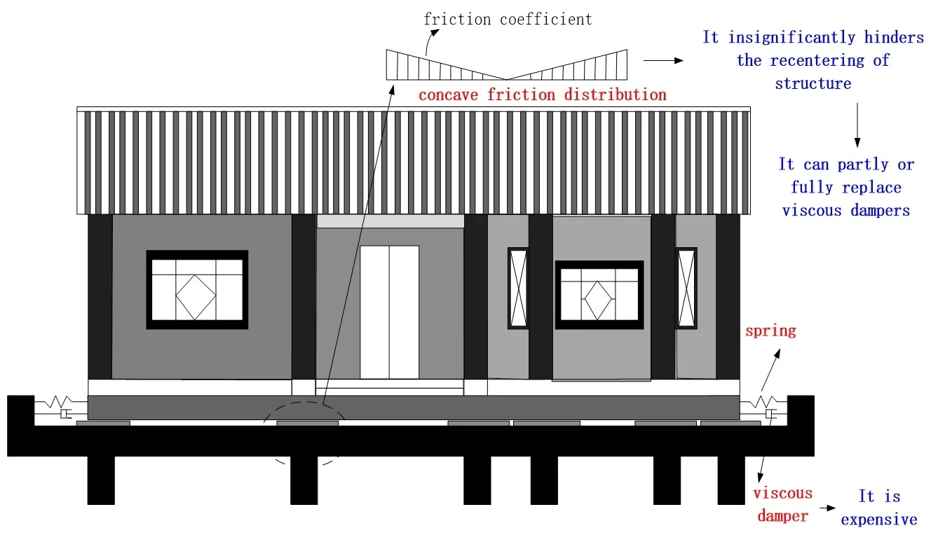
Seismic isolation devices were designed to protect three similar building structures, containing different objects with different fragilities, in a strong earthquake region. And a performance-based assessment framework, established by the PEER, was used to identify the seismic isolation efficiency of these devices. It optimized the ratios of spring part, viscous damping part and friction part in the seismic isolation devices, aiming at different functional buildings. Results show that a spatially concave friction distribution, combined with a weak spring, not only can reduce the structural acceleration response during earthquakes, but also decrease the structural residual displacement after earthquakes. Moreover, the spatially concave friction distribution can dissipate earthquake energy, but cannot hinder the recentering of structure like that of general uniform friction distributions. Consequently, the spatially concave friction distribution can partly or fully replace the viscous dampers, which are more expensive and short-lived. The reasonable combination of different components in the seismic isolation devices can satisfy different seismic requirements, aiming at different functional buildings.
Highlights
- A spatially concave friction distribution should combine with a weak spring
- It reduces the structural acceleration response during earthquakes
- It decreases the structural residual displacement after earthquakes
- The spatially concave friction distribution can partly or fully replace viscous dampers
1. Introduction
Many viscous damper-spring or other similar devices, such as rubber bearings combined with viscous dampers, have been invented and researched to reduce structural seismic damages in recent decades. However, these devices are often interfered by a frictional action, when the devices or isolated structures contact with other objects [1]. For example, a horizontal contact surface is often used to support long-term service loadings [2]. However, this contact surface becomes a frictional interface due to a relative displacement during earthquakes, and disturbs the seismic isolation efficiency of the viscous damper-spring devices [3]. It means that most of the seismic isolation systems contain a spring part, a viscous damping part and a friction part.
The spring part, such as a rubber bearing or a spring device, is necessary for a traditional isolation system, since it can reduce the relative and residual displacements between the structure and the ground. What’s more, the spring constant should be small, which aims to prolong the natural vibration period of structure and make this period be much larger than the predominant periods of earthquakes [4]. However, the small spring constant will enlarge the structural displacement responses.
The viscous damping part, such as a viscous damper, is usually added to dissipate earthquake energy. It can reduce the structural displacement responses in a certain extent during earthquakes.
The friction part, such as the friction interface above supporting the structural long-term service loadings, can also dissipate earthquake energy, when the structure slides on the friction interface during earthquakes.
There were some discussions on the viscous damping function and the frictional function as follows:
(1) Both the viscous damping part and the friction part could dissipate earthquake energy. However, Chung et al. [5] suggested that an isolation system might not be very effective if selecting an inappropriate damping. So it was necessary to rigorously simulate the viscous damping part and the friction part in a numerical analysis. If the friction component is ignored, it would get a wrong seismic response [1].
(2) Those viscous dampers were discovered leaking oil, and therefore their service life was much shorter than the common civil structures that they were used in [6]. Meanwhile, more frictional devices with a long service life have been developed. For example, Harvey and Gavin [7] proposed double rolling isolation systems (RISs). They found that the friction-based isolation devices had perfect seismic isolation performance, long service lives and low cost [2].
(3) The frictional action was often equivalent to the viscous damping. For example, the viscous damping ratio of uniform friction distribution was assumed to be 2/π in previous seismic calculations [8]. However, the frictional action and the viscous damping action are different from each other, although both of them can dissipate energy. The spatially uniform friction distribution prevents the structure from sliding back to the initial site after earthquakes, while the general viscous damping action doesn’t have such a negative function [1].
Based on the discussions above, the friction component was better than the viscous damping component, except that the frictional action prevented the structure from moving back to the initial site after earthquakes. After investigating the uniform friction distribution, the convex friction distribution and other variable friction distributions in space [1-9], it had a summary that a spatially concave friction distribution, combining with an appropriate spring component, would not prevent the structural restoration [10]. As for the spatially concave friction distribution, the friction coefficient has the smallest value in the contact center, and increases when the structure moves away from the contact center.
This paper tried to numerically obtain the optimal seismic performance of three similar isolation structures, by combining the spring component, the viscous damping part and the friction part. The above concave friction distribution was rigorously simulated, and was used to partly or fully replace the viscous damping component. This replacement has several merits:
(1) It will reduce the cost by decreasing the ratio of the expensive viscous damping component in the seismic isolation devices.
(2) It will prolong the service life of viscous damper, because the force undertaken previously by the viscous damper is reduced by sharing with the frictional force during earthquakes.
(3) The concave friction distribution makes full use of the friction component, which is always there between the structure and the ground. For example, the concave friction distribution can avoid some negative functions, such as hindering the structural recentering, of the traditionally uniform or rondomically variable friction distributions.
2. Structure
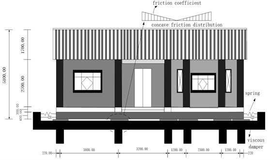
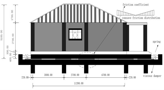
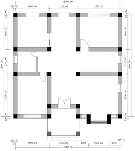
A large number of civil engineering structures have been built for many years in China. Some similar or even the same structures are often designed for different places by one design institute, since this kind of structure has some merits and promotional value [1]. There are three similar building structures (300 tons), which are built at three different sites in a severe earthquake zone. The design project of the main structure is shown in Fig. 1. It is designed, with a very strong foundation, columns and beams, to resist the future earthquake. These buildings have a story, and short vibration periods. The seismic isolation devices are used to prolong the structural motion periods on the bottom surface of building structures. This treatment will reduce the internal force of the building structures with short vibration periods during earthquakes. The seismic isolation devices contain the spring devices, the viscous damper devices and the concave friction distribution devices as shown in Fig. 1.
Fig. 1A building structure: a) elevation view (mm), b) side view (mm), c) plan view (mm)
a)
b)
c)
The damage states (DS) of generally isolated structures are defined in Table 1.
(1) The structural peak acceleration response, which is used to imply the intensity of structural internal force, is the most important index of seismic isolation.
(2) The structural relative displacement is an insignificant index, when the structural foundation and the gap between the structure and other objects are all large enough. These large constructions can avoid the structural sliding away from the foundation and colliding with adjacent objects during earthquakes, however, increase the construction cost of structure.
(3) A small residual displacement implies it is easier or less costly to repair the structure after earthquakes.
Table 1Damage states (DS) or capacities (C) of generally isolated building structures
Seismic response | Units | C = DS1 | C = DS2 | C = DS3 | C = DS4 |
Acceleration | m/s2 | 0.25 | 0.50 | 0.75 | 1.00 |
Relative Displacement | m | 0.20 | 0.40 | 0.80 | 1.60 |
Residual Displacement | m | 0.02 | 0.04 | 0.08 | 0.16 |
Table 2Three different design principles for three similar building structures at three sites
Structural number | Objects in structure | Earthquake | Structural allowable probability exceeding damage states in Table 1 | ||
Acceleration | Relative displacement | Residual displacement | |||
1 | Museum pieces of art | Ground motions in Fig. 2, PGA = 0.8 g | C = DS2: 30 % | C = DS3: 40 % | C = DS3: 10 % |
2 | Precious equipment | C =DS3: 30 % | C = DS3: 40 % | C = DS2: 10 % | |
3 | Common objects | C = DS4: 30 % | C = DS3: 15 % | C = DS2: 5 % | |
Because the above three similar building structures contain different objects, the design institute provides three different design principles for them as shown in Table 2.
Structure 1: the rigorous requirement of acceleration response is set since the museum pieces of art in it are very sensitive to ground motions, while the displacement response requirement is relaxed.
Structure 2: a larger acceleration response is allowed since the precious equipment in it can resist larger ground motions than the museum pieces of art in structure 1. The same considerably large relative displacement as that of structure 1 is allowed for structure 2, however, a less residual displacement is provided to reduce the repair cost of structure 2 after earthquakes.
Structure 3: the largest acceleration response is set to protect the structure itself but not the objects in it, because the common objects are not sensitive to ground motions. However, the more rigorous requirement of displacement response is provided to reduce the structural costs during the construction stage and the reparation stage.
3. Ground motions
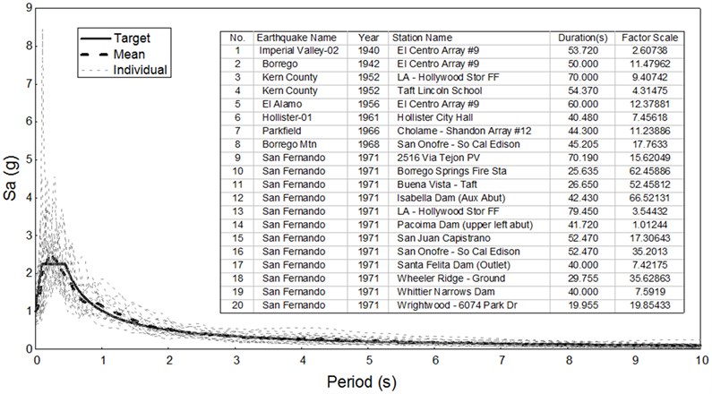
Because the seismic safety assessment report shows that there are very thick soft soils with the shear wave velocity between 140 and 250 m/s at the three building sites, the Chinese III response spectrum [11] is selected for the target spectrum as shown in Fig. 2. Being consistent with the target spectrum, 20 ground motions were chosen from the database of Pacific Earthquake Engineering Research Center (PEER, 2015). The mean spectrum of the scaled 20 ground motions is close to the target one with a peak ground acceleration (PGA) of 0.8 g. These 20 recordings are input into the isolation structure as the ground motions.
4. Numerical methods
The performance-based seismic design [12] needs seismic hazard analysis, response analysis, damage analysis and loss analysis. However, this framework can be simplified to only include the response analysis and the damage analysis, for the aim of evaluating the vulnerability of the three different structures under earthquakes.
Each case was calculated by a time history program, compiled by the authors [4]. And then a lot of structural responses were obtained. These seismic responses were compared with the damage states (DS), defined in Table 1. Finally, the probabilities, exceeding each damage state, were obtained, when different seismic isolation devices were used by combining different spring components, viscous damping components and friction components.
Fig. 2Target spectrum, mean spectrum with PGA = 0.8 g and individual earthquake spectra
5. Design of seismic isolation devices
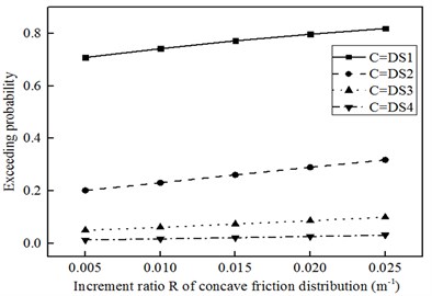
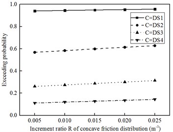
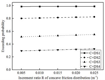
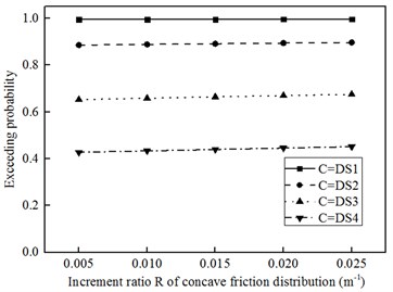
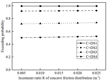
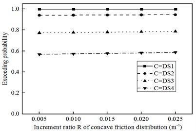
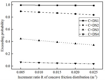
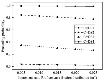
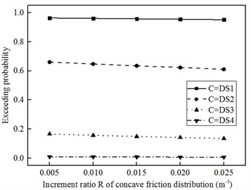
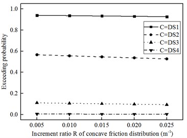
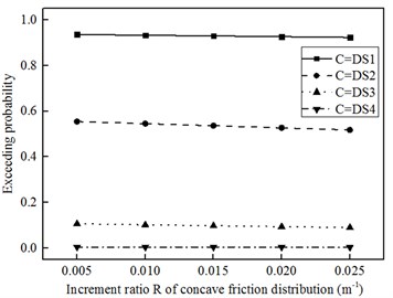
Fig. 3, 4 and 5 describe the probabilities of three different structural responses, exceeding different damage states in Table 1, when subjected to the earthquakes with PGA = 0.8 g as shown in Fig. 2. From Fig. (a) to Fig. (f) in Fig. 3, 4 and 5, the total spring constants K of seismic isolation devices adopt 100, 200, 300, 400, 500 and 600 kN/m, respectively. And the total damping constants D only select the critical value, aiming at the minimized seismic responses [8], which considers the influence of concave friction distribution [1].
As for the spatially concave friction in Fig. 1, the friction coefficient has the smallest value of μ0= 0.005 in the contact center, and an increment ratio R of 0.005, 0.010, 0.015, 0.020 and 0.025 m-1, respectively. It implies that the friction coefficient increases, when the structure moves away from the contact center [1].
Based on the structural allowable probabilities exceeding the damage states in Table 2, the optimal spring constant K, damping constant D and increment ratio R of spatially concave friction distribution are identified for the three similar building structures in Fig. 1.
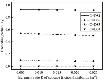
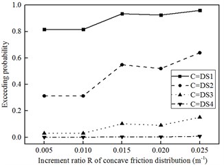
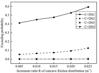
Structure 1: it contains the vulnerable museum pieces of art and has the most rigorous requirement of acceleration response. A seismic isolation device, with small parameter values of K=100 kN/m, D=50 kN·s/m and R=0.02 m-1, can be identified as the optimal project for structure 1. Based on Fig. 3(a), 4(a) and 5(a), the probabilities of structural acceleration, relative displacement and residual displacement, exceeding DS2, DS3 and DS3 in Table 1, are 29 %, 36 % and 9 %, respectively. These probabilities satisfy the requirement in Table 2.
Structure 2: the precious equipment in structure 2 can resist a larger acceleration response than the museum pieces of art in structure 1. Therefore, a seismic isolation device, with larger parameter values of K=200 kN/m, D=100 kN·s/m and R=0.02 m-1, can be identified as the optimal project for structure 2. Furthermore, these larger parameter values of seismic isolation device reduce the displacement responses. The probabilities of structural acceleration, relative displacement and residual displacement, exceeding DS3, DS3 and DS2 in Table 1, are 30 %, 28 % and 9 %, respectively, in Fig. 3(b), 4(b) and 5(b). These probabilities satisfy the requirement in Table 2.
Fig. 3Structural acceleration probabilities exceeding different damage states when PGA = 0.8 g: a) K= 100 kN/m, D= 50 kN·s/m, b) K= 200 kN/m, D= 100 kN·s/m, c) K= 300 kN/m, D= 200 kN·s/m, d) K= 400 kN/m, D= 250 kN·s/m, e) K= 500 kN/m, D= 250 kN·s/m, f) K= 600 kN/m, D= 250 kN·s/m
a)
b)
c)
d)
e)
f)
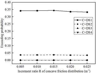
Structure 3: when a seismic isolation device adopts K=300 kN/m, D=200 kN·s/m and R=0.01 m-1, the probabilities of structural acceleration, relative displacement and residual displacement, exceeding DS4, DS3 and DS2 in Table 1, are 30 %, 15 % and 4 %, respectively. These probabilities satisfy the requirement in Table 2. On the one hand, Table 2 gives the loose requirement of acceleration response, which protects the structure itself instead of the common objects in it. On the other hand, Table 2 gives the more rigorous requirement of displacement response, which reduces the structural costs during the construction and reparation stages.
Fig. 4Structural relative displacement probabilities exceeding different damage states when PGA = 0.8 g: a) K= 100 kN/m, D= 50 kN·s/m, b) K= 200 kN/m, D= 100 kN·s/m, c) K= 300 kN/m, D= 200 kN·s/m, d) K= 400 kN/m, D= 250 kN·s/m, e) K= 500 kN/m, D= 250 kN·s/m, f) K= 600 kN/m, D= 250 kN·s/m
a)
b)
c)
d)
e)
f)
6. Discussions
The above optimal parameters of seismic isolation devices depend on the three similar structures themselves and the objects in them, respectively. In any cases, a small spring constant, such as K=100 kN/m for structure 1, K=200 kN/m for structure 2 and K=300 kN/m for structure 3, should be used to avoid a too large value of structural acceleration response.
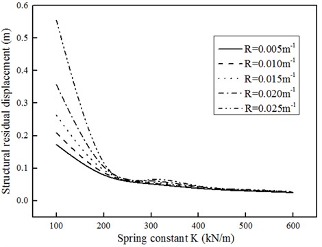
However, the smaller spring constant implies the reduced restoring capacity of seismic isolation system or the increased residual displacement after earthquakes. The friction coefficient μ=μ0+RΔ, preventing the structural restoring, depends on the residual displacement Δ on the spatially concave friction surface. It has the smallest friction coefficient value μ0 in the contact center, and an increment ratio R of unit length. Based on the mechanical equilibrium of KΔ=μmg or KΔ=(μ0+RΔ)mg in Fig. 1, the structural static residual displacement Δ is Δ=μ0mg/(K-Rmg) or Δ=μ0/(K/mg-R) as shown in Fig. 6. The equation and Fig. 6 indicate that an increase of spring constant decreases the structural residual displacement, while an increase of μ0 and R increases the structural residual displacement.
Fig. 5Structural residual displacement probabilities exceeding different damage states when PGA = 0.8 g: a) K= 100 kN/m, D= 50 kN·s/m, b) K= 200 kN/m, D= 100 kN·s/m, c) K= 300 kN/m, D= 200 kN·s/m, d) K= 400 kN/m, D= 250 kN·s/m, e) K= 500 kN/m, D= 250 kN·s/m, f) K= 600 kN/m, D= 250 kN·s/m
a)
b)
c)
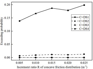
d)
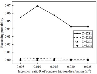
e)
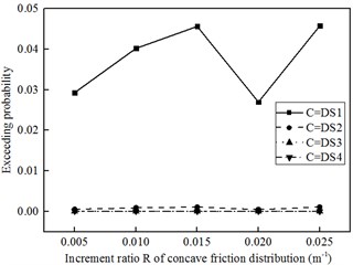
f)
In Fig. 6, the static value Δ is very sensitive to R when K is very small, such as K=100 kN/m. And in this stage, the static value Δ significantly decreases when K increases. However, when K becomes more than 200 kN/m, the static value Δ insignificantly decreases with the increased K. And in this stage, the static value Δ is not sensitive to R.
However, the discussions above only evaluate the maximum residual displacement using a static equilibrium of KΔ=μmg or KΔ=(μ0+RΔ)mg in Fig. 1. The practical residual displacement is always less than the static value Δ=μ0/(K/mg-R), because the weak ground motion at the end of earthquakes causes the structure to a new position within ±Δ. For example, the probabilities of structural residual displacement exceeding DS3 in Table 1 is only 9 %, although the theoretical value of Δ=μ0/(K/mg-R) is 0.36 m, being much larger than 0.08 m of DS3 in Table 1, when K=100 kN/m, and R=0.02 m-1 for structure 1.
As to further reduce Δ, it is a better way to reduce μ0 in the contact center. If a superlubrication technology [13] is used, μ0=0 and the structural residual displacement will be 0. However, this superlubrication technology has been only seen in some physical experiments, but has not been used in civil engineering structures.
Although the viscous damper doesn’t prevent the structural restoration, the theoretical viscous damper-spring isolation system, ignoring the frictional action, is not real in practical civil engineering structures [14]. In fact, the friction is always in any practical civil engineering structure, and prevents the structure from moving back to the initial site after earthquakes [15]. In contrast, this paper uses the spatially concave friction distribution to replace a part of the expensive viscous damper, and to increase the restoring capacity of seismic isolation devices. However, the energy dissipation efficiency of frictional action is less than that of viscous damper [16]. Therefore, the viscous damper is still needed to reduce the structural relative displacement response, although the spatially concave friction distribution is used [17]. If the requirement of structural relative displacement is very loose during earthquakes, the expensive viscous damper is not needed and the seismic isolation system becomes a spring-friction system.
Fig. 6The static value Δ of structural residual displacement
7. Conclusions
This paper studied on the seismic isolation device, containing the spring part, viscous damping part and friction part. And the optimal combinations of these parts in the seismic isolation device were selected for three different functional buildings in a strong earthquake region. The conclusions are summarized as follows:
1) By combining the spring part, viscous damping part and friction part in different way, it can satisfy the different performance-based requirements for the structures with different functions under earthquakes.
2) A small spring constant should be adopted in order to avoid a too large acceleration response of structure in a strong earthquake region, such as PGA = 0.8 g. The spatially concave friction distribution, combined with the appropriate spring, can not only dissipate earthquake energy, but also partly or fully replace the expensive viscous dampers.
3) The static residual displacement of Δ=μ0/(K/mg-R) is useful. The practical residual displacement is always less than the static value Δ=μ0/(K/mg-R), because the weak ground motion at the end of earthquakes causes the structure to a new position within ±Δ.
4) By using Δ=μ0/(K/mg-R) or Fig. 6 in practical design, an appropriate combination of a spring constant K and a spatially friction increment ratio R can be firstly obtained to satisfy the acceleration and residual displacement requirements. And then, an appropriate damping constant D can be added to significantly decrease the structural displacement responses. Trial calculation is needed, because the viscous damper can insignificantly change the structural acceleration and residual displacement responses.
References
-
Wei B., Yang T. H., Jiang L. Z. Influence of friction variability on isolation performance of a rolling-damper isolation system. Journal of Vibroengineering, Vol. 17, Issue 2, 2015, p. 792-801.
-
Tsai C. S., Lin Y. C., Chen W. S., Su H. C. Tri-directional shaking table tests of vibration sensitive equipment with static dynamics interchangeable-ball pendulum system. Earthquake Engineering and Engineering Vibration, Vol. 9, Issue 1, 2010, p. 103-112.
-
Wei B., Yang T. H., Jiang L. Z., He X. H. Effects of friction-based fixed bearings on the seismic vulnerability of a high-speed railway continuous bridge. Advances in Structural Engineering, Vol. 21, Issue 5, 2018, p. 643-657.
-
Wei B., Dai G. L., Wen Y., Xia Y. Seismic performance of an isolation system of rolling friction with spring. Journal of Central South University, Vol. 21, Issue 4, 2014, p. 1518-1525.
-
Chung L. L., Kao P. S., Yang C. Y., Wu L. Y., Chen H. M. Optimal frictional coefficient of structural isolation system. Journal of Vibration and Control, Vol. 21, Issue 3, 2015, p. 525-538.
-
Ataei H., Mamaghani M., Anaraki K. K. Seismic response study of degraded viscous damping systems for tall buildings in China. Structures Congress, Denver, 2017.
-
Harvey P. S., Gavin H. P. Assessment of a rolling isolation system using reduced order structural models. Engineering Structures, Vol. 99, 2015, p. 708-725.
-
Zeng Q. Y., Zhou Z. H., Wen Y. Lectures of dynamics of structures. China Communication Press, Beijing, 2015, (in Chinese).
-
Wei B., Wang P., He X. H., Jiang L. Z. The impact of the convex friction distribution on the seismic response of a spring-friction isolation system. KSCE Journal of Civil Engineering, Vol. 22, Issue 4, 2018, p. 1203-1213.
-
Wei B., Wang P., Liu W. A., Yang, M. G., Jiang L. Z. The impact of the concave distribution of rolling friction coefficient on the seismic isolation performance of a spring-rolling system. International Journal of Non-linear Mechanics, Vol. 83, 2016, p. 65-77.
-
JTJ004-89:1989. Standard of the Ministry of Communications of P.R., 1989.
-
Yang T. Y., Stojadinovic B., Moehle J. Demonstration of a practical method for seismic performance assessment of structural systems. Earthquake Spectra, Vol. 28, Issue 2, 2012, p. 811-829.
-
Rani R., Kumar N., Kozakov A. T., Googlev K. A., Sankaran K. J. Superlubrication properties of ultra-nanocrystalline diamond film sliding against a zirconia ball. RSC Advances, Vol. 5, Issue 122, 2015, p. 100663-100673.
-
Siringoringo D. M., Fujino Y. Seismic response analyses of an asymmetric base-isolated building during the 2011 Great East Japan (Tohoku) Earthquake. Structural Control and Health Monitoring, Vol. 22, Issue 1, 2015, p. 71-90.
-
Wei B., Zuo C. J., He X. H., Hu Q. Y. Earthquake isolation of a spring-damper-friction system with a convex friction distribution. Journal of Testing and Evaluation, Vol. 22, Issue 4, 2019, p. 1203-1213.
-
Wei B., Wang P., He X. H., Jiang L. Z. Seismic isolation characteristics of a friction system. Journal of Testing and Evaluation, Vol. 46, Issue 4, 2018, p. 1411-1420.
-
Wei B., Zhuo Y., Li C., Yang M. Parameter optimization of a vertical spring-viscous damper-coulomb friction system. Shock and Vibration, Vol. 2019, 2019, p. 5764946.
About this article
This research is jointly supported by the National Natural Science Foundations of China under grant No. 51778635 and 51778630, the Natural Science Foundations of Hunan Province under grant No. 2019JJ40386, the Xuzhou science and technology project under grant No. 201718, the project of Jiangsu Housing and Urban-rural Development Department under grant No. 2017ZD012, and the Science and Technology Project of Sichuan Province under grant No. 2019YFG0048. The above support is greatly appreciated.
In this paper, Shanshan Li calculated the isolation system and wrote the English language. Biao Wei compiled the computer program. Chaobin Li analyzed the calculation data. Weihao Wang draw the figures. Yunji Fu modified and improved the paper.

