Abstract
Based on analysis of principle of interval velocity measurement system and characteristics of target signal, this paper proposed a thought to research accurate extraction of target signal by obtaining the completed target signal. A real-time high-speed storage method based on ARM7 and double NAND memory is proposed in this paper, and is used to deposit the completed target signal. This method lays foundations for achieving high-speed continuous firing velocity measurement, as well as the study on accurate extraction technology of the target signal. The technology has been successfully applied to a muzzle velocity calibration system, and the completed target signals and data of continuous firing velocity measurement have been obtained, which shows the performance is reliable and steady.
1. Introduction
Artillery external ballistic is calculated based on muzzle velocity, muzzle velocity is also an important technical indicator to examine artillery and ammunition whether to meet the design requirements. At present the domestic use of projectile muzzle velocity measurement methods are: Radar velocimetry method, coil target velocimetry method, sky screen velocimetry method, light screen velocimetry method etc. These velocimetry methods are mostly district section principles of velocimetry system. The main principles of the velocity measurement system by measuring the time used which projectile passing through two known distance velocity measurement targets. According to the average velocity measurement to get the average speed of projectile between velocity measurement targets, then get the muzzle velocity by calculating. Velocity measuring accuracy of this method depends on the extraction of projectile target signal, the timing precision and the target distance measurement accuracy, with the development of high-precision timers and length accurate measuring instruments, the extraction of the projectile passing through the target signal is still based on fixed trigger threshold, the extraction accuracy of the projectile target signal has become a major factor in velocimetry accuracy of district section principle velocimetry system.
If we carry out the study on accurate extraction technology of projectile passing through the target signal, firstly we should get the full projectile passing through the target signal. In the paper, the method is proposed that high-speed storage for projectile passing through the target signal based on ARM7 and double NAND memory. This method can achieve in real-time high-speed storage of projectile passing through the target signal, laying the foundation for achieving high-speed continuous velocity measurement and the study on accurate extraction technology of the projectile passing through the target signal.
2. Measurement of target signal with typical velocity-measuring system
It is very suitable to using non-contact measurement technology for fast-moving projectiles. The actual position of the projectile can’t be measured directly, but certain features which the shells perform in a particular environment can be measured directly. Coil Target and Sky Screen Target carry out the speed tests by changes of magnetic flux and light intensity which be caused by projectile passing through the target surface.
Sky Screen Target is measured by measuring the shell image location and time. As shown in Fig. 1, shell imaged onto the detector. When the shell is moved to a different location, optical signal intensity is different on the detector. Projectile target signal is shown as Fig. 2.
Fig. 1The principle diagram of sky screen target velocity measurement
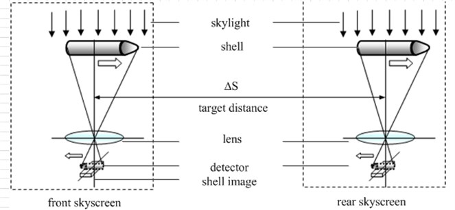
Fig. 2Schematic diagram of target signal
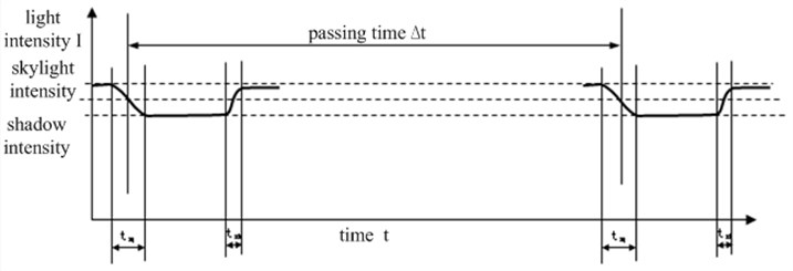
On the direction of shell movement, placing two sky screen targets vertically with pitch of ΔS. Measuring the time ΔT of passing front and rear sky screen target, we can calculate the average speed Vm of the shell.
As can be seen from Fig. 2, the rising and falling edges of the photoelectric signal is directly related to the decision threshold level. The magnitude of the signal is changed with the changes of daylight, and therefore accurately select the threshold level is more difficult, so that the measurement accuracy of time ΔT subject to greater impact. When the threshold level is not within the intensity range of daylight and shadows image, the time and the speed can't be measured. This is a big reason that sky screen target velocity precision is easily influenced by environment such as daylight intensity. The principle of the coil target velocity measurement is similar to sky screen, there are also some problems that accurately selected threshold level is more difficult and time measurement accuracy is significantly influenced. So to carry out the study on accurate extraction technology of projectile passing through the target signal, it is urgent to get a complete target signal of projectile.
3. Method of high-speed storage of target signal
The length of projectile is generally less than 1000 mm, the range of speed is generally 50-1800 m/s. Projectile through the target time is not more than 0.5 seconds, typically ten milliseconds, sampling according to 1 MHz, total data of projectile through target are not exceed 100 Kbyte. For the continuous firing mode, the amount of data increase multiply, if the continuous acquisition 10 seconds or longer, data bytes will be 10 MB or more. According to the system sampling frequency, the number of chips required can be estimated by processor processing speed, storage time of memory chip and the time required to reach the storage memory. Calculations are shown in Table 1.
Table 1Direct memory required to the number of storage chips at different sampling rates
Sampling rates | Time reach storage (ms) | Number of chips | Storage time (ms) |
520 | 246 | 1.2 | 100 |
720 | 178 | 1.7 | 100 |
1000 | 128 | 2.3 | 100 |
1428 | 90 | 3.3 | 100 |
2000 | 64 | 4.7 | 100 |
2720 | 47 | 6.4 | 100 |
If the memory is used to direct continuous storage, at least three memories are needed. It is obviously that increase the complexity of hardware circuit. In the paper, FIFO buffer technology is proposed, the technology of large capacity data storage based on ARM7 and double NAND memory can achieve data continuous high-speed direct storage. The schematic diagram of the system is shown as Fig. 3.
Fig. 3Schematic diagram of the large capacity data storage
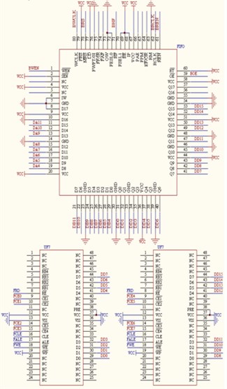
The collected data first enters the FIFO buffer. When the half-full flag of the FIFO buffer chip is valid, it means that half of the FIFO storage capacity has been used and the data are stored in Flash A. When the full flag of the FIFO buffer chip is valid, it indicates that the storage capacity of FIFO has been used up, and Flash A is still writing operation, then transferring these data to Flash B. When the half-full flag is valid again, it indicates half of the capacity storage of the FIFO has been used and Flash A has finished the write operation while Flash B is now writing data to Flash A. When the full flag effectively once again, it means that the storage capacity of the FIFO has run out, and Flash B has finished writing while Flash A is still doing the write operation, shifting data to flash B. Flash A and Flash B are used alternatively in the way described above to achieve high-speed storage. The storage process of NAND memory is shown in Fig. 4. The front and rear target signals are simultaneously carried out ADC conversion and stored in the two flash separately. The Flash memory here is continuous and cycling used. For example, if the sampling rate is 100 KHz, and the sampling duration is 100 s, each of the original sampling data is 10 MB, so the memory can store 200 experiment data altogether. When the memory is full, the stored data will be erased to make room for new data.
Fig. 4NAND storage process diagram

3.1. Central CPU microprocessor
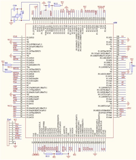
Central CPU microprocessor is the control center of the whole measurement system, ARM7 micro-control processor is adopted which is an industrial processor. This processor is stable, powerful, able to complete a full control, computing and communications work. ARM7 is applied to the measurement and control, trigger signals of the front and rear light screens have been carried out ADC conversion, and stored in FLASH. The trigger time of front and rear light screens are also recorded in a register. The main characteristics of ARM7-PLC2214 as follows:
• 16/32 bit ARM7TDMI-S microprocessor, LQFP144 package.
• 16 KB on-chip static RAM and 128/256 KB on-chip Flash program memory. 128-bit wide interface / accelerator can achieve high working frequency up to 60 MHz.
• Vectored Interrupt Controller. Priorities and vector addresses can be configured.
• Memory can be configured into four groups through external memory interface, the capacity of each group is up to 16 Mb, data width is 8/16/32 bit.
• Up to 112 general I/O port (5 V tolerant), 9 edges or level-triggered external interrupt pin.
• CPU operating frequency which maximum is up to 60 MHz is obtained by On-chip PLL.
• The range of on-chip oscillator frequency: 1-30 MHz.
Fig. 5Reading sequence diagram of NAND
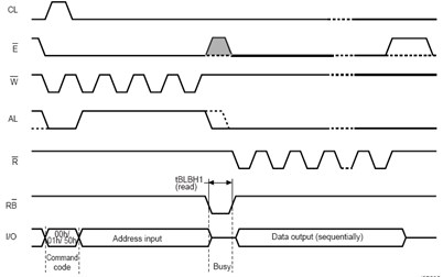
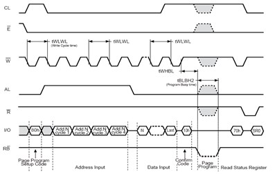
Fig. 6Writing sequence diagram of NAND
3.2. NAND memory
High-speed large-capacity non-volatile memory should be chosen to achieve data storage at a high speed. The design capacity of FLASH memory is 1 GB. 8 KB of FIFO is used between the ADC and memory in order to match with FLASH page storage interface port. NAND-type FLASH is chosen by its typical write speed of 1.28 M/s. Write timing shown in Fig. 5 and Fig. 6. FLASH uses industrial-grade chips NAND512W3A2DN6E of NUMONYX Company.
Based on the reading and writing timing of memory, C++ is used to achieve the reading and writing operations of NAND memory. Program code is show in Table 2.
Table 2Program code
NAND memory writing programs | NAND memory reading programs |
void nand_write_halfpageA(uchar adr1,uchar adr2,uchar adr3) { uint j; nand_sendc(0x00); nand_sendc(0x80); nand_senda(0x00,adr1,adr2,adr3); nand_e=0; nand_cl=0; nand_al=0; nand_r=1; j=0; do { nand_w=0; P1=buffer[j]; nand_wait(); j++; nand_w=1; P1=0xff; } while(j<256); nand_e=1; nand_sendc(0x10); nand_rb=1; while(!nand_rb); do { nand_readstatus(); } while(!(nand_status==0xe0)); } | void nand_read_halfpage(uchar cmd, uchar addr_p1,uchar addr_p2,uchar addr_p3) { nand_senda(0x00,addr_p1,addr_p2, addr_p3); //delay(25);//15us nand_rb=1; while(!nand_rb); nand_e=0; nand_cl=0; nand_al=0; nand_w=1; P1=OXFF; Ii=256; do { nand_r=0; uint i; //jugde cmd valide nand_sendc(cmd); _nop_(); _nop_(); _nop_(); _nop_(); _nop_(); buffer[i]=P1; nand_r=1; P1=0xff; i++; } while(i<512); nand_e=1; } |
3.3. Physical system of high-speed storage and measured waves
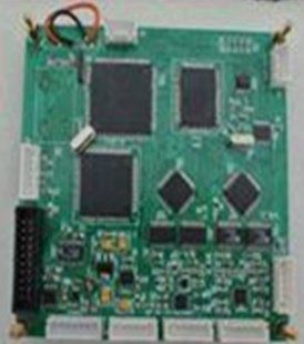
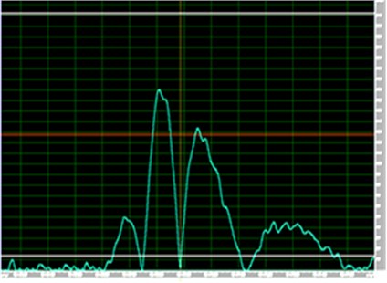
The system has been successfully applied to an open laser target muzzle velocity calibration system, and complete projectile passing through the target signal is achieved. High-speed memory circuit of projectile passing through the target signal and measured projectile passing through the target signal are shown in Fig. 7. The system is successful obtained a certain type of high-speed repeating firing of artillery test. The data are stable and reliable. Test data are shown as Table 3.
Physical of high-speed memory circuit and a complete projectile target signal as shown in Fig. 7.
Table 3Continuous firing speed of a certain type artillery Unit: m/s
Sequence number | Sky screen target | Laser target | ||
First | First | Second | Third | |
1 | 812.8 | 815.34 | 813.63 | 808.72 |
2 | 804.7 | 808.25 | 810.61 | 811.63 |
3 | 810.8 | 813.64 | 811.23 | 806.92 |
4 | 802.5 | 806.10 | 808.11 | 809.43 |
Fig. 7Physical system of high-speed storage and measured waves
4. Conclusions
In this paper, the technology of ARM7 integrating with double NAND memory capacity of continuous data acquisition and storage is proposed. It not only solves the problem of projectile velocity measurement at the high-speed firing mode, but also original information data recorded can be conducted in-depth and detailed analysis, promoting research on extraction techniques of projectile passing through the target signal. Through the complete passing through the target signal record store, ensure that complete information of each shot will not miss, the experimental data availability and success rate are improved, which has high time and economic benefits.
References
-
Sun Qiang Determination of projectile muzzle velocity. CFHI Technology, 2002, p. 52-53.
-
Ren Guoming, Gao Senlie, He Zhengqiu, et al. Introduction of ballistic defense technology laboratory equipment and Features. Journal of Ballistics, Vol. 7, Issue 1, 1995, p. 89-96.
-
Shen Yong, Di Changan, Wang Changming Analysis of velocity measurement with single coil target. Journal of Transducer Technology, Vol. 20, Issue 12, 2001, p. 10-12.
-
Ni Jinping, Tian Hui, Jiang Linyan Design of amplifying and converting circuit for coil target signal. Journal of Test and Measurement Technology, Vol. 18, Issue 4, 2004, p. 316-319.
-
Li Hanshan, Gao Hongyao Improve and study system of skyscreen accuracy measurement. Modern Electronic Technique, Vol. 18, 2003, p. 12-14.
-
Yu Xiaojun, Wang Xuanze, Xie Tiebang Bullet velocity measurement system based on photoelectric signal conversion principle. Journal of Hubei Polytechnic University, Vol. 17, Issue 4, 2002, p. 105-107.
-
Zhu Linyue, Gao Jin, Li Chaowei Research on muzzle velocity measurement system based on dual laser screen. Journal of Gun Launch and Control, Vol. 1, 2010, p. 67-70.
