Abstract
This paper presents the design of a control technique applied to the pneumatic active suspension system of a quarter car model using controller with fuzzy logic embedded in the active force control component. The overall control system is decomposed into two loops. In the main loop the desired force signal is calculated using an active force control strategy with a sugeno fuzzy logic element which is being employed to estimate the mass needed to feed the control loop. A Mamdani fuzzy logic controller is implemented in the outer loop to design a force controller such that the desired force signal is achieved in a robust manner. The resulting control strategy known as fuzzy – active force controller (FLC-AFC) is used to control a nonlinear actuator attached between the sprung mass and the unsprung mass of the quarter car model. The performances of the proposed control method were evaluated and later compared to examine the effectiveness in suppressing the vibration effect of the suspension system. Resulting fuzzy active force control gives better results if compared to the fuzzy logic and the passive suspension system.
1. Introduction
The main objective of the automobile industry is to achieve both ride comfort and the ride stability to get the passenger and the drivers feeling more comfortable. The high quality of the ride comfort can be obtained by two ways, the first by minimizing the axis and angular acceleration of the gravity centre of the vehicle body while the second is by maintaining the tire contacts with the ground when the wheel strikes a bump [1]. The function of automotive suspension system is not only to isolate the effect of road surface irregularities on the passengers to improve the ride comfort but also it has to control the dynamic tyre load with acceptable suspension working space to enhance the vehicle stability and safety. The dynamic tyre load is the main effect of tire/road friction forces which are controlling the vehicle lateral stability during handling maneuver’s and braking, stopping distance, traction forces as well as tyre rolling resistance [2-3]. The automotive suspension systems are categorized into three types, namely passive, semi-active and active suspensions [4]. Passive suspension consists of spring and damper, because of its fixed characteristics it cannot control the design range described above [5-6]. Active suspension differs from the conventional passive suspension in which an actuator is attached in parallel with both the spring and the shock absorber to inject energy into the system. The main advantage of employing an active suspension system is that it offers adaptation potential, where the suspension characteristics can be adjusted while driving to accommodate the profile of the road being traversed [7]. With this taken into account the controller design, tuning and intelligent controllers also improve the performance of the active suspension [8-10]. Intelligent control is an emerging control area that is stimulated by continuous advancement in computing technology. Paper [11] used fuzzy logic control (FLC) to minimize vertical car body acceleration and to avoid hitting suspension limits. Fuzzy logic control has been applied successfully in vehicle suspension systems to evaluate the control performance, but the application of fuzzy logic control still requires considerable effort in determining appropriate membership functions and fuzzy rules. This is particularly true if the system is complicated or rapidly changing. Active suspension systems generally possess nonlinear and uncertain dynamic characteristics, making it more difficult to design a fuzzy logic controller for these [12]. Due to the controller design and response time of the actuator, it produces either insufficient or excess value of force. The investigations to avoid this issue by designing an active force control loop are performed.
2. Mathematical modeling
2.1. Quarter car modelling
The vehicle model considered in this study is quarter car model. The system consists of the passenger seat, sprung mass, unsprung mass, air spring and a passive damper as shown in Figure 1. Assumptions of a quarter car modeling are as follows: the tire is modeled as a linear spring without damping, there is no rotational motion in the wheel and the body, the behaviors of spring and damper are linear, the tire is always in contact with the road surface and effect of friction is neglected so that the residual structural damping is not considered in the vehicle modeling [13].
Fig. 1Quarter vehicle two degree of freedom model
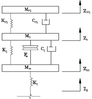
Table 1Values of parameters
Symbol | Parameter | Value | Units |
Cps | Seat damping constant | 875 | Ns/m |
Cs | Suspension damping constant | 1000 | Ns/m |
Fa | Actuator force | ± 2000 | N |
Ks | Suspension stiffness | 18100 | N/m |
Kus | Tire stiffness | 196000 | N/m |
Kps | Seat stiffness | 10507 | N/m |
Mps | Passenger seat mass | 60 | kg |
Ms | Sprung mass | 290 | kg |
Mus | Unsprung mass | 59 | kg |
Equations of motion for active quarter car model are given by the following:
where Zs is displacement of sprung mass, Zusis displacement of unsprung mass, Zr is road profile, Fa is air spring force and the following Table 1 parameter values are used in the simulation.
2.2. Air spring dynamics
There are different control strategies adopted under the semi active suspension system, each one having its own characteristics. The ideal goal of an optimal suspension is to minimize the sprung mass relative displacement and acceleration. However these two criteria are in conflict. In general a suspension system with a small relative displacement corresponds to a high sprung mass acceleration and a large relative displacement corresponds to a low sprung mass acceleration [14].
To determine the force or load at any given point in the stroke of an air spring the atmospheric pressure must be backed out of the absolute pressure values to yield gauge pressure. A typical value of the absolute pressure is p=300-700 kPa. The force on the spring at any given point of the load deflection curve is the gauge pressure multiplied with the effective area [15]:
The force developed by the pneumatic actuator can be evaluated from the above equation:
Here consider polytrophic process for air:
Differentiation of Equation (6) with the purpose to find an expression for the pressure change gives:
The sign convention generally used is that positive pressure changes are given by positive displacements. Since positive pressure results from compression of the contained volume, thus:
Extracting the pressure change from Equation (7) and inserting Equation (8) gives:
Depending on the velocity of the excitation (frequency) different stiffness constants are derived. The dynamic stiffness can be expressed as follows:
The quasic-static stiffness:
Therefore the static stiffness of the air spring is given by:
If the change in effective stiffness with deflection is very small, i.e. there is constant effective area, the stiffness constants can be assumed to be:
where γ is the value CpCv=1.4 for air, z is the displacement (m), Ae is the effective area (m2), V is the volume (m3), Fz is the vertical force (N), Kz,dyn is the dynamic vertical stiffness (N/m), Kz,stat is the static vertical stiffness (N/m), P is the absolute pressure (Pa), Pg is the gauge pressure (Pa) and Pa is the atmospheric pressure (Pa) [15].
3. Controller design
Main controller design is very difficult because it is necessary to regard the complicated system to obtain the good control effect. In order to enable the air suspension control system with a certain degree of adaptive capacity, the fuzzy controller is designed. Velocity of sprung mass and deflection of suspension were adapted as input variables of fuzzy controller, while the output variable was air spring force. Their ranges could be obtained through simulation, five fuzzy language subsets were used to describe two input variables and output variables. Membership functions of the subsets were triangle and trapezoidal functions. The rule is in the form of the linguistic variables using the fuzzy conditional statement. Each rule is derived from the characteristic of the passive suspension system. Fuzzy rule base is combination of all possible control rules and it is summarized in Table 2. Mamdani’s minimum operation rule is used as a fuzzy implication function. As a process usually requires a non-fuzzy value of control, a method of defuzzification called “Centre of gravity method” (COG) is used here, where μD(f) is corresponding membership function in Equation (18) [16]. The air spring force (fa) is chosen to give ±2 kN as maximum and minimum values:
Table 2Rule base
zs-zus | ˙zs | ||||
NL | NS | ZE | PS | PL | |
NL | PL | PS | PS | ZE | NS |
NS | PL | PL | PS | PS | ZE |
ZE | PS | PS | ZE | NS | NL |
PS | PS | ZE | NS | NL | NL |
PL | ZE | NS | NS | NL | NL |
4. Active force control system
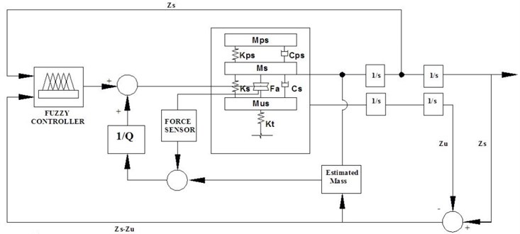
AFC loop is as shown in Fig. 2 and is designed to compensate the system subjected to a number of disturbances in order that it remains stable and robust via the compensating action of the control strategy for the unknown disturbances. The efficiency of the AFC strategy relies on the mass estimator as the body acceleration and the actuator force are easily obtained. The AFC scheme has two inputs, namely the active force pneumatic actuator and body acceleration components. The estimation of mass needed by AFC loop is the main factor which contributes to the effectiveness of the control scheme. Active force control system utilizes three controller loops. AFC loop is integrated with outer Fuzzy Logic controller and inner Force Tracking controller. FLC is used in the outer loop for the computations of the optimum target commanded force. Force tracking of the pneumatic actuator is carried out by a fuzzy controller. AFC loop uses intelligent method (Fuzzy Logic) for the estimation of mass and from the measured values of acceleration and force of the dynamic system for the computation of the estimated force. This error signal is used to compensate for the known/unknown disturbances. Sugeno type Fuzzy Inference System is used for the estimation of mass. The main aim of using the Fuzzy Logic in the study is to compute the estimated mass intelligently so that it can be utilized by the AFC mechanism to affect its control strategy. Membership functions representing the input (suspension deflection and body acceleration) and output (estimated mass) of the FLC used in the input membership functions are chosen as Gaussian functions. The output is a singleton value of the estimated mass. Once FLC is designed it is embedded in the overall control strategy for online estimation of the mass and thereafter it estimates the force [17]. A more detailed description on the mathematical treatment related to the derivation of important equations and stability criterion can be found in [17, 18]:
where Q is the estimated disturbance force, F is the measured force, M is the estimated mass and a is the measured acceleration. If the parameters are appropriately measured or estimated, then a guaranteed robust AFC performance is achieved [18, 19].
Fig. 2Block diagram of active force control system for air spring suspension
5. Results and discussion
To generate the road profile of a random base excitation for the 3-DOF active suspension simulation disturbance, a spectrum of the geometrical road profile with road class roughness D is considered as shown in the Table 3. The vehicle is travelling with a constant speed v0, the time histories data of road irregularity are described by PSD method [20-22]. According to International Standard Organization (ISO) 2631 [12], the ride comfort is specified in terms of root mean square (RMS) acceleration as shown in Table 4 [23].
To verify the PID and fuzzy air spring actuator controlled suspension it is compared with passive suspension. Here Matlab/Simulink is used as a computer aided control system tool for modeling the non-physical two degree of freedom quarter car with actuators and its modeling is included in one analysis loop. To verify the system, the body acceleration and suspension deflection parameters are considered. And for the given input parameters the response of the system is observed on 5 seconds scale.
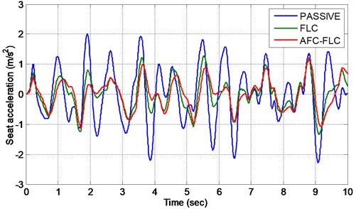
The Figures 3, 4 show the accelerations of seat and sprung mass respectively. With this we can easily identify that both pneumatic controlled and active force control loop systems are superior in performance over passive suspension system. Fuzzy controlled and active force controlled systems are of the same trend, due to the fact that the pneumatic actuator develops desired force between the sprung mass and the unsprung mass. Also due to lower transmissibility of air spring the RMS acceleration of the system also reduces the vibration. Passive RMS acceleration values of seat and sprung mass are in uncomfortable range according to the Table 4.
Table 3Road roughness value classified by ISO
Classification S (Ω) | Road roughness K [m2/(cycles/m)] (×10-6) | |
Range | Average | |
A (Very Good) | 2 to 8 | 4 |
B (Good) | 8 to 32 | 16 |
C (Average) | 32 to 128 | 64 |
D (Poor) | 128 to 512 | 256 |
E (Very Poor) | 512 to 2048 | 1024 |
Table 4Acceleration level and Degree of comfort defined in ISO2631-1 [24-26]
Acceleration level | Degree of comfort |
Less than 0.315 m/s2 | Not uncomfortable |
0.315-0.63 m/s2 | A little uncomfortable |
0.5-1 m/s2 | Fairly uncomfortable |
0.8-1.6 m/s2 | Uncomfortable |
1.25-2.5 m/s2 | Very uncomfortable |
Greater than 2 m/s2 | Extremely uncomfortable |
Fig. 3Acceleration of seat for D-class random road
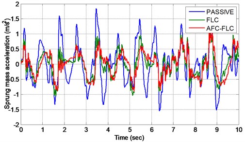
Fig. 4Acceleration of sprung mass for D-class random road
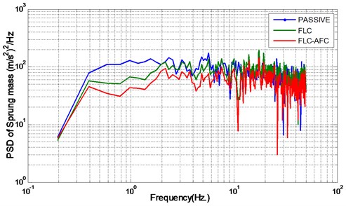
The Figures 5, 6 show the power spectral densities of seat and sprung mass respectively. Seat frequency of proposed system is superior in all the frequency range of 0.1 Hz to 80 Hz. Power spectral density of sprung mass of the proposed system is superior in the lower frequency range.
Fig. 5Power spectral density of seat for D-class road
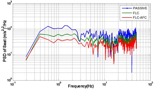
Fig. 6Power spectral density of sprung mass for D-class road
RMS acceleration comparison is presented in Table 5.
Table 5RMS acceleration comparison and reduction
Description | Passive | FLC | FLC-AFC | % of reduction |
Seat acceleration (m/s2) | 0.8138 | 0.5223 | 0.4870 | 40.15 |
Sprung mass acceleration (m/s2) | 0.5883 | 0.4430 | 0.4230 | 28.90 |
6. Conclusions
In this paper it has been discussed about the designing of active force control loop for pneumatic air spring actuator. Mamdani and sugeno fuzzy interference systems are used to control and for estimating of air spring actuator in order to improve the ride comfort and road handling in a quarter car model. Simulation results are obtained from Matlab/Simulink. Comparisons between passive, fuzzy and active force control techniques are done and the results prove that the performance of air spring suspension with active force control can improve the ride comfort and road handling.
References
-
Eltantawie M. A. Decentralized neuro-fuzzy control for half car with semi-active suspension system. International Journal of Automotive Technology, Vol. 13, Issue 3, 2012, p. 423-431.
-
WongJ. Y. Theory of ground vehicles. 3rd Edition, Wiley-Inter Science, New York, 2001.
-
Mahmoud El-Kafafy, Samir M. El-Demerdash, Al-Adl Mohamed Rabeih Automotive ride comfort control using MR fluid damper. Engineering, Vol. 4, 2012, p. 179-187.
-
Milad Geravand, Nastaran Aghakhani Fuzzy sliding mode control for applying to active vehicle suspentions. Wseas Transactions on Systems and Control, Vol. 5, 2010.
-
Mailah M., Priyandoko G. Simulation of a suspension with adaptive fuzzy active force control. Int. Simul. Model., Vol. 6, Issue 1, 2007, p. 25-36.
-
Mouleeswaran Senthil Kumar Genetic algorithm-based proportional derivative controller for the development of active suspension system. Information Technology and Control, Vol. 36, Issue 1, 2007.
-
Priyandoko G., Mailah M., JamaluddinH. Vehicle active suspension system using skyhook adaptive neuro-active force control. Mechanical Systems and Signal Processing, Vol. 23, 2009, p. 855-868.
-
Aldair A. A., WangW. J. Design an intelligent controller for full vehicle nonlinear active suspension systems. International Journal on Smart Sensing and Intelligent Systems, Vol. 4, Issue 2, 2011.
-
Seiyed Hamid Zareh, Atabak Sarrafan, Meisam Abbasi, Amir Ali Akbar Khayyat Intelligent neuro-fuzzy application in semi-active suspension system. Fuzzy Logic – Controls, Concepts, Theories and Applications, 2012.
-
Rahmi Guclu, Kayhan Gulez Neural network control of non-linear full vehicle model vibrations. Vibration Control, 2010.
-
D’Amato F. J., ViassoloD. E. Fuzzy control for active suspensions. Mechatronics, Vol. 10, 2000, p. 897-920.
-
Jeen Lin, Ruey-Jing Lian, Chung-Neng Huang, Wun-Tong Sie Enhanced fuzzy sliding mode controller for active suspension systems. Mechatronics, Vol. 19, 2009, p. 1178-1190.
-
Nusantoro G. Priyandoko PID state feedback controller of a quarter car active suspension system. J. Basic. Appl. Sci. Res., Vol. 1, Issue 11, 2011, p. 2304-2309.
-
T. Ram Mohan Rao, G. Venkata Rao Analysis of passive and semi active controlled suspension systems for ride comfort in an omnibus passing over a speed bump. International Journal of Research and Reviews in Applied Sciences, Vol. 5, Issue 1, 2010.
-
Malin Presthus Derivation of air spring model parameters for train simulation. Lulea University of Technology, 2002.
-
Salem M. M. M., Ayman A. A. Fuzzy control of a quarter-car suspension system. World Academy of Science, Engineering and Technology, Vol. 53, 2009.
-
Rajeswari K., LakshmiP. Simulation of suspension system with intelligent active force control. IEEE International Conference, 2010.
-
Hewit J. R., BurdessJ. S. Fast dynamic decoupled control for robotics using active force control. Transactions on Mechanisms and Machine Theory, Vol. 16, Issue 5, 1981, p. 535-542.
-
Metered H., Bonello P., OyadijiS. O. The experimental identification of magnetorheological dampers and evaluation of their controllers. Mechanical Systems and Signal Processing, Vol. 24, Issue 4, 2010, p. 976-994.
-
Chen Y. Skyhook surface sliding mode control on semi-active vehicle suspension systems for ride comfort enhancement. Engineering, Vol. 1, Issue 1, 2009, p. 23-32.
-
Gavriloski V., Jovanova J. Dynamic behavior of an air spring elements. Machines, Technologies, Materials, International Virtual Journal, 2006, p. 24-27.
-
Quaglia G., Sorli M. Air suspension dimensionless analysis and design procedure. Veh. Syst. Dyn., Vol. 35, 2001, p. 443-475.
-
Ramji K., Gupta A., Saran V. H., Goel V. K., KumarV. Road roughness measurements using PSD approach. Journal of the Institution of Engineers, Vol. 85, 2004, p. 193-201.
-
International Organization for Standardization. Mechanical Vibration and Shock – Evaluation of Human Exposure to Whole-Body Vibration – Part 1: General Requirements, ISO 2631-1, 1997.
-
Chikako Kaneko, Takahide Hagiwara Scaling and evaluation of whole body vibration by the category judgment method. Technical Papers and Articles, Yamaha Motor Technical Review, 2005.
-
Senthikumar M., Vijaya Rangan Linear quadratic regulator controller design for active suspension system for random road surfaces. Journal of Scientific and Research, Vol. 65, 2006, p. 213-226.
About this article
I would like thank university grand commission RGNF scheme for the financial support and Anna University for providing research support.
