Abstract
This paper presents a detailed analysis and comparison of large salient-pole synchronous generators (SPSG) with conventional slot distributed and fractional slot concentrated winding techniques for power generation applications. The fractional slot concentrated winding technique (FSCW) makes it possible to increase the machine inductance and permeability of the poles in order to achieve lighter, cheaper and high-efficiency SPSGs with a simpler structure without reducing the output power. The SPSGs are modeled and analyzed by using ANSYS MAXWELL packet program which is a Finite Element Method (FEM) based electromagnetic field simulation software. Detailed comparisons of the SPSGs’ performance characteristics which include important issues such as wave form of the induced voltage, weight and cost of the machines, machine losses and saturation effect are presented. Guidelines are developed to help electrical machine designers faced with reducing the saturation of the SPSGs’ poles.
1. Introduction
Mankind’s need for electrical energy is increasing with each passing day. To cope with the increase, new power plants should be built or the capacity and efficiency of existing power plants should be increased. The most important unit of a power plant is the generator, which converts the rotating mechanical power of the turbine into electrical energy. In power production plants and with grid-supplied or converter-supplied high power electric motors, salient-pole synchronous generators (SPSG) have been widely used for decades [1].
One of the problems with conventional slot distributed winding (CSDW) SPSG is magnetic saturation in the iron cores [2]. The magnetic saturation limits the armature terminal voltage and the machine requires more excitation power, which leads to additional losses in the damper windings, therefore the efficiency of the machine decreases. The magnetic saturation can be reduced by enlarging the cross sectional area of the field windings. However, the rotor pole-bodies should be reduced in this case in order to maintain the total machine size and this causes another increase in the flux density. As a consequence, the maximum output power of the generator does not increase or the dimensions of the machine do not decrease despite the increase in the magneto-motive force (MMF). In this case, the efficiency of generator considerably decreases or/and the total weight of the generator increases. In order to overcome these design limits FSCW technique may be used. Actually, this FSCW technique has been used for flux weakening operations for achieving constant-power speed range in the surface permanent magnet (PM) synchronous machines (SMs) designed for small power applications [3-5]. It is possible to present a design approach for achieving iron cores with higher permeability in generator poles by properly designing the machine's stator windings using FSCWs in the stator. Otherwise, as a result of this winding topology, lower weight and cost can be achieved without reducing the output power. Concentrated windings refer to windings that encircle a single stator tooth; eliminating any end-winding overlaps with other phase windings thus preventing the saturation of the poles. The comparison between conventional distributed and concentrated windings has been shown in Fig. 1.
A major objective of this paper is to provide a clear explanation of how concentrated fractional-slot windings make it possible to achieve lighter, cheaper and higher-efficiency SPSGs with simpler structures without reducing the output power. Additional advantages of the approach have been discussed including magnetic saturation, cogging torque in two-teeth and cost. MAXWELL software is conducted for achieving this desired performance characteristics. The analysis results of two layers per slot 2.4 MVA SPSG designed by using FSCW technique are compared with conventional (CSDW) SPSG. Addition to this, performance characteristics of the both SPSGs are investigated and evaluated machine losses by taking into account to eddy effect has been presented.
Fig. 1Comparison of stator winding configurations
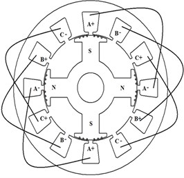
a) CSDW – overlapping winding
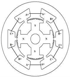
b) FSCW – concentrated non-overlapping winding
2. Concentrated winding theory
Distributed windings can make better use of the stator and rotor structure and also decrease harmonics comparing to concentrated windings [6]. On the other hand, concentrated windings offer some significant advantages over distributed windings. These include: simpler construction, no large end connections, low copper usage and losses, significantly higher slot fill factor (78 %), reduction in the total length of the machine [3], reduction in machine manufactured weight and also cost, no mutual inductance between phases causing a higher fault tolerance [7], lower per-unit stator winding resistance, and providing higher inductance compared to distributed windings for the same magnetic flux linkage. Due to the segmentation of the stator core, it is possible to use pre-made coils in the stator. The coils are made up of rectangular copper conductors manufactured under tension. Furthermore, less cooling material is required for the cooling of the stator windings because of the large range of the available space of the stator slots. However, there are a number of well-known disadvantages associated with concentrated windings such as [8]: higher cogging torque especially in PM machines, potential for higher acoustic noise and vibration especially in PM machines, low winding factor, lower output torque due to a low winding factor, decrease in saliency ratio, and higher eddy-current losses in high-speed PM machine applications.
2.1. Calculation of winding factors for SPSGs
The fundamental component of the resultant MMF created by the stator currents of a SM with conventional windings is given by Eq. (1):
where Nph is the total number of turns of the phase winding formed by these coils, P is the number of poles, ia is the peak value of the phase current and θ is the current angle. The winding factor (kwh) including h order harmonic is calculated as in Eq. (2):
where is the pitching factor, is the distribution factor of the winding and is the skewing factor, is the stator coil pitch in electrical degrees and is the pole pitch in mechanical degrees, is the number of slots per pole per phase, is the phase number, is slot pitch in mechanical degrees, is the number of slots and is the skew angle which is the angle between the first lamination’s slot and its corresponding slot in the last lamination along the axial direction. Reduction techniques [9] often contribute to a machine with weaker performance. On the other hand, the MMF of a SPSG with FSCWs is given by Eq. (3):
where is the number of layers in each slot. According to Eq. (3), to be able to design compact and high efficiency SMs, the winding factor should be as high as possible, since for an electrical machine with a low winding factor a higher current or more winding turns are required in order to provide the same MMF. As a result of the low winding factor, the copper losses, total dimensions, total weight and also the cost of the machine increase and the efficiency decreases. On the other hand, high winding factors cause higher harmonic order. Optimal winding factor should be chosen for a good sinusoidal output voltage of the FSCW generator taking account the .
2.2. Winding factors and the value
Selecting the value for SPSG is very important in terms of machine performance. value in the SPSGs is limited according to PMSM since, in the SPSG, the number cannot be greater than number due to lack of enough space for the poles and a low value [10]. Choosing the preferred value depends on , , , and machine symmetry as seen in Eq. (2). Selecting the and numbers as high as possible reduces the total harmonic distortion (THD). This leads to an increase in cogging torque frequency and a decrease in its magnitude. Product of the and indicating machine symmetry should be an even number for a low net radial force on the machine. must be compatible with the value. A single-layer stator winding has advantages in terms of production compared to double-layer stator winding. Although easily reproducible, a single-layer stator winding has higher THD value than double-layer stator windings. Fundamental winding factors for double-layer concentrated windings for different combinations of pole numbers and slot numbers are given in [11]. Usually, the winding factor () increases with and values. However, it is possible to increase the by varying the slot pitch factor () and/or distribution factor (). In this study, is developed by experimental combination of and . As an example, the value of the conventional SPSG is chosen 2.875 and FSCW SPSG is chosen as 0.625. A double-layer, 15Q, 8P, 2.4MVA FSCW SPSG was designed and compared with double-layer, 69Q, 8P, 2.4MVA conventional SPSG.
2.3. Slot leakage inductance
The slot leakage component of the inductance should be taken into account because of significantly large stator slots. Furthermore, slot leakage inductance can account for more than 50 % of the total inductance of machines equipped with concentrated windings. In FSCW machines, phase inductance is generally dominated by the slot leakage component and not the air-gap component, especially for large effective air-gaps. This is primarily caused by the increase of the cross-slot leakage component; although as the effective air-gap is reduced, the air-gap component becomes more important.
The slot and end-winding components of inductance for overlapping windings machines can be evaluated by the standard method [12]. However, in machines having non-overlapping windings and two different phase windings are accommodated at the sides of a slot, the slot leakage self and mutual inductance per slot can be evaluated by using Eq. (4) [12]:
where the simplified permeance coefficients, , , are given by Eq. (5) [13]:
These have a significantly lower mutual inductance, which is evident since the slot opening geometry has a noticeable effect on inductance, which becomes more significant as the effective air-gap length is increased. Assuming that the air-gap field is homogeneous:
As specific slot permeance increases, slot leakage inductance and reactance will increase as well. Furthermore, while leakage fluxes increase, the magnetic field density of the pole body () will decrease. As a result, will remain approximately constant. Eventually, even if the leakage flux increases, the induced EMF given in Eq. (3) will not decrease. This significant development will lead to a decrease in the dimensions of the machine preventing the saturation of pole bodies without decreasing the output voltage and efficiency.
3. Design and analysis
A 2.4 MVA, 6.6 kV/50 Hz, double-layer 15 slots-8 poles (15Q8P), FSCW SPSG was designed and compared with a double-layer 69 slots-8 pole (69Q8P), 2.4 MVA, 6.6 kV/50 Hz conventional SPSG. Obtained data are analyzed by using FEM to prove the accuracy of implementation of the FSCW method on large SPSGs. Analysis results including magnetic density, flux lines, relative permeability and performance curves are given in section 4. The model chosen for this analysis has slots that are very deep, rectilinear and little in quantity, making it an attractive choice for FSCW configurations.
As the first step, which is very important in the design of a SPSM to achieve lighter, cheaper and high-efficiency SPSGs with simpler structure and the ability to increase the permeability of the pole body iron cores using FSCW is to choose the optimum slot-per-phase-per-pole ().
The winding distribution deviates from a standard sinusoidal distribution in FSCW machines. Therefore, classical 1D analytical techniques including , complex vector and AC phasor techniques cannot be used for FSCW SPSM analysis with sufficient precision due to their much larger effective air-gaps and also the armature leakage reactance. A numerical approach based on a 2D analytical technique for calculating the magnetic field produced by the stator windings of any 3-phase AC machines is adopted [14]. This proposed model takes flux focusing and leakage effects into account. The predicated distributions have been obtained by using MAXWELL packet program based on FEM.
Electrical machines required an accurate mathematical model for system simulation and performance evaluation. Detailed knowledge of the air-gap flux distribution of an SPSG plays a very important role in a safe estimation of the characteristics of the machine's torque and efficiency. The distribution of magnetic flux can be calculated analytically for very simple geometries. In most cases, the distribution of magnetic flux is obtained through the usage of numerical methods like FEM, Finite Difference Method (FDM) or a Boundary Elements Method (BEM). The simulation was completed using the following steps [15]; 1) Geometric model creation, 2) The appointment of the materials that make up the structure of the machine, 3) Boundary conditions and mesh process, 4) The appointment of currents in windings, 5) Analyze, 6) Examination of the results.
Table 1General data
Rated apparent power (kVA) | 2400 |
Rated power factor | 0.8 (Ind.) |
Rated voltage (kV) | 6.6 (Inf. Bus.) |
Winding connection | Wye |
Number of poles | 8 |
Frequency (Hz) | 50 |
Rated speed (rpm) | 750 |
Operating temperature (°C) | 115 |
Friction and windage loss(W) | 9050 |
Exciter efficiency (%) | 95 |
To test and compare all mechanical and characteristic properties with the FSCW machine, a 15Q8P SPSG and a 69Q8P SPSG were designed. The requirements were modified to require infinite bus operation as a generator synchronized with the network (50 Hz, 6.6 kV). Table 1 summarizes the requirements for the designed machines. The key machine dimensions, core materials and stator winding data are given in Table 2. As seen in this table, the winding factor of the CSDW machine is 22.167 % higher than the FSCW machine. M36_29G steel material is used as iron core material in both stator and rotor.
Table 2Stator winding and core data
Feature | CSDW | FSCW | Feature | CSDW | FSCW | |
Outer diameter of stator (mm) | 1090 | 1120 | Hs0 | 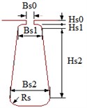 | 1 | 8 |
Inner diameter of stator (mm) | 748 | 698.5 | Hs1 | 3 | 2 | |
Length of stator core (mm) | 760 | 600 | Hs2 | 95 | 135 | |
Coil pitch | 7 | 1 | Bs0 | 17 | 25 | |
No of conductors per slot | 16 | 110 | Bs1 | 17 | 48.6 | |
Net slot area (mm2) | 1683 | 8170.12 | Bs2 | 17 | 69 | |
Slot fill factor (%) | 62.668 | 78 | Rs | 0 | 6 | |
Stator winding factor | 0.9135 | 0.711 | ||||
As can be seen from Table 2 and Table 3, even though the lengths of the machines are the same, the stator dimension of FSCW is larger and the rotor dimensions of FSCW are smaller than CSDW. The reason for this is the deeper slots required for FSCWs. The optimal values are chosen for high efficiency and a smooth sinusoidal wave form of the induced voltages, and this leads to a low THD, low cogging torque in two teeth and more stable output values. Actually, the stator winding factor of the FSCW design develops 14.485 % by experimental combination of and as mentioned in the previous section. Detailed field-winding data of the designed machines are also given in Table 3. The dimensions of the designed coil for the FSCW are lower because of its smaller rotor dimensions. FSCW has a simple structure thus is one. As a result of , the machine winding can be made much simpler as seen from Fig. 1.
Table 3Rotor winding and core data
Feature | CSDW | FSCW | Feature | CSDW | FSCW |
Minimum air gap (mm) | 3 | 3.25 | Pole-body height (mm) | 130 | 125 |
Inner diameter (mm) | 220 | 200 | Width of wire (mm) | 39 | 31.5 |
Pole-shoe width (mm) | 210 | 200 | Thickness of wire (mm) | 1.0 | 1.18 |
Pole-shoe height (mm) | 48 | 42 | Number of turns per pole | 76 | 70 |
Pole-body width (mm) | 110 | 105 | Wire wrap thickness (mm) | 0.3 | 0.3 |
4. Analysis results
Both designed machines were required to meet the same generator operating output performance requirements, including 2.4 MVA at 750 rpm synchronous speed (50 Hz). In addition, the machines were all constrained to have the same stator and rotor stack length, almost same dimensions and air-gap length. A significant reduction (14.077 %) has been achieved in the total weight of the SPSG owing to FSCW technique as seen in Table 4. For the FSCW generators, to be able to induce enough voltage in the stator windings, more copper was used because of the significant leakage reactance and also leakage fluxes in the stator, air-gap and the rotor. Actually, concentrated windings with have a significant reduction in the length of the end turns. Using this feature of FSCW machines, the saturation of the iron core of the machine can be prevented without reducing the length of the machine. In this study, to be able to achieve the optimal weight of the FSCW generator, the length is reduced with optimal saturation in the rotor iron core. Cost calculations of the designed machines has been also evaluated and the obtained results have been summarized in Table 4. The cost of an electrical machine depends on the number of electrical machines of the same type manufactured per year, manufacturing equipment, the cost of the winding, the cost of the ferromagnetic core and components dependent on the size of the core (frame, end disks, bearings, etc.), the cost of all other components independent of the shape of the machine, e.g. nameplate, encoder, terminal board, terminal leads etc. and the organization of the production process, quality of materials and other aspects and cost of labor [16]. Active material cost calculations have been evaluated with respect to London Metal Exchange (LME) industrial metals trading and cost-risk management. LME copper is 7.264 US$/Kg, LME Aluminium Alloy (Al) is 1.815 US$/Kg and LME Steel is 0.3 US$/Kg [17].
Table 4Active material weights and cost
CSDW | FSCW | |||
Component | Weight (kg) | Cost ($) | Weight (kg) | Cost ($) |
Windings | 934.015 | 6.784.68 | 883.97 | 6.421.16 |
Core steels | 2818.4 | 845.52 | 2342 | 702.6 |
Ring + bar (Al) | 180.9 | 328.33 | 153.64 | 278.85 |
Total net | 3933.31 | 7958.53 | 3379.61 | 7402.61 |
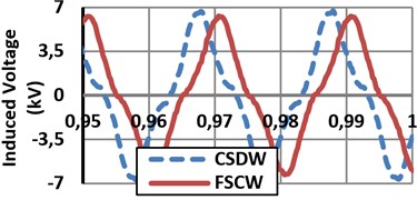
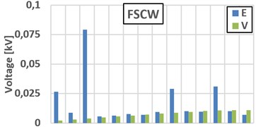
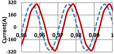
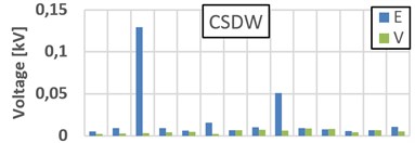
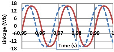
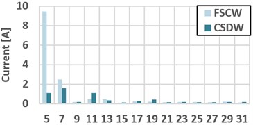
When FSCW SPSG connected to grid, voltage and current THD levels are 0.55 % and 3.33 %, respectively. When CSDW SPSG connected to grid, voltage and current THD levels are 0.189 % and 0.835 %, respectively. Terminal voltage and stator current THDs of the terminal voltages of the both FSCW machines are within the IEEE 519 voltage distortion limits (max. 5 % voltage THD) [18]. Also as a result of the skewing, a more sinusoidal induced voltage is achieved as given in Fig. 2(a). As seen in Fig. 2(d), harmonic levels of the terminal voltage is very low. On the other hand, 9th and 21th harmonic levels of induced voltage on the stator windings are higher on both generators. As a natural result of the flux weakening operation, the value of the induced voltage of the FSCW is lower due to its higher leakage fluxes and also the lower winding factor as given in Eq. (3). As a natural result of more flux leakage and a short active length, the induced voltage on the FSCW machine’s stator winding is lower than the CSDW machine’s. Sinusoidal currents and flux linkage of the Phase A for both machines are given in Fig. 2(b) and (c), respectively. When the designed generators are connected to the infinite bus network their current wave form will be as in Fig. 2(b) with almost the same (0.8) power factor. Although the armature copper mass of the FSCW generator is heavier (17.855 %) than CSDW machine, the armature resistances are almost same as seen in Table 8. Thus, the armature current density of the FSCW generator is lower.
Variation of cogging torque, THD and efficiency values according to different skew factors are given in Table 5. Whole analysis results are obtained according to 0.7 slot skew width for the FSCW machine and 0 (not skewed) for CSDW machine. As clearly seen in Table 5, while skew width increases cogging torque, which causes acoustic noise, vibration and high torque ripples, and also THD value, which is very important for grid connection and power efficiency issues, degreases. According to Table 5, it is possible to say that the skew width factor is not proportional with the machine efficiency. Because over-skewing reduced the value of the induced voltage on the stator windings. In addition, the wave form of the induced voltage and its harmonic orders are given in Fig. 2(a) and (d), respectively.
Fig. 2a) Induced voltage on the phase A stator windings; b) Current of phase A at full-load; c) Flux linkages of phase A under full-load condition, d) Terminal voltage (V), induced voltage (E) and current harmonics orders of SPSGs
a)
b)
c)
d)
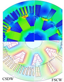
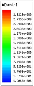
After the required analysis, the full load data of the designed machines are summarized in Table 6 and the operating characteristics of the machines are compared. The results are almost the same as anticipated, as seen in Table 6. Load data under the full-load operation condition and efficiency parameters are evaluated whereas the power factor of the both machines are 0.8. As seen from the table, total losses consist of 51.5 % copper, 10.8 % stranded, 9.7 % core, and 28 % other losses. As a result of the analysis it is figured out that the eddy current losses in the FSCW generator is 7.23 % less than the CSDW one, because of high flux leakages and low iron core material consumption. In addition, there are harmonic stator losses induced in the stator laminations due to the effect of saturated rotor iron cores that have a similar effects as the stator slots. The efficiency of the FSCW generator, which is smaller in size and lighter in weight, is slightly greater; it does not reach saturation regardless of having the same output characteristics as the CSDW generator. As a result of FSCW technique, the armature leakage reactance of the FSCW generator is significantly higher (almost 500 %) than CSDW generator. In order to figure out the accurate distribution, the flux leakages and the line forms, the magnetic flux line distribution of both machines are shown in Fig. 3. Designed machine’s magnetic flux densities indicating the core saturation regions at full-load generator operation and the average value of the magnetic densities are given in Fig. 3 and Table 7, respectively.
Table 5Effect of skewing
CSDW SPSG | FSCW SPSG | |||||
Distor \ skew width | 0 | 0.25 | 0.7 | 0 | 0.25 | 0.7 |
Cogging torque (N·m) | 0.2906 | 0.0146 | 0.00601 | 6.1328 | 0.3287 | 0.1353 |
Voltage THD (%) | 0.189 | 0.151 | 0.064 | 3.4041 | 0.814 | 0.55 |
Efficiency (%) | 96.0677 | 96.075 | 96.0715 | 96.586 | 96.465 | 96.1138 |
Table 6Full-load data and efficiency parameters
Data results | CSDW | FSCW | Power loss (kW) | CSDW | FSCW |
Phase voltage (V) | 3810.51 | 3810.51 | Iron core | 7.36 | 7.45 |
Phase current (A) | 209.946 | 209 | Stranded | 8.2 | 7.6 |
Stator current density (A/mm2) | 5.161 | 4.93 | Copper | 38.9 | 40.1 |
Field current density (A/mm2) | 3.8 | 4.74 | Friction and windage | 9.05 | 8.05 |
Average moving torque (kN·m) | 31.4 | 22.1 | Additional | 12 | 12 |
Peak to peak torque (kN·m) | 1.67 | 5.467 | Total loss | 75.51 | 75.2 |
Apparent power (kVA) | 2400 | 2389.2 | Output lower | 1844.5 | 1860 |
Table 7Average full-load magnetic data
B (T) | CSDW | FSCW |
Stator-teeth | 1.78 | 1.14 |
Stator-yoke | 0.88 | 1.31 |
Pole-shoe | 1.48 | 1.64 |
Pole-body | 1.7 | 1.31 |
Rotor-yoke | 0.98 | 0.95 |
Air-gap | 0.63 | 0.84 |
As seen from the average flux densities of the machine parts, although the length of the FSCW generator is 21.052 % shorter and the outer diameter is 2.752 % longer than the CSDW generator, it has lower magnetic flux densities on its iron core parts. This means that the FSCW generator can be operated with higher load without reaching saturation. The FSCW generator has higher flux leakages as expected. As the resultant flux density moves around the air-gap, so does the spatial variation of the permeability, suggesting that the permeability variation can be viewed as a traveling wave in the air-gap. In addition, when teeth saturation occurs, the decrease in the permeability of the iron paths has the effect of increasing the teeth reluctances for the region around the resultant component of the air-gap flux.
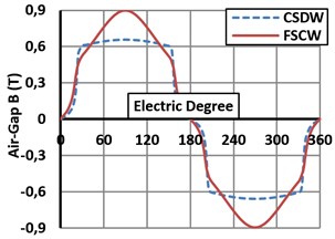
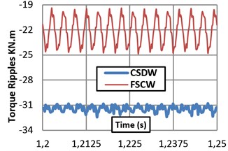
The air-gap flux density, which is very important in terms of the harmonics of the induced voltage in the stator windings, is given in Fig. 4(a). In addition, the air gap flux has a harmonic content that is a function of the machine saturation. After the required FEM analysis, it is substantiated that the slot leakage inductance is very high compared to conventional machines with small stator slots as seen in Table 8 and Fig. 3 (magnetic flux lines). These extra slot leakages cause to flux-weakening and more torque ripple as seen in Fig. 4(b), stronger vibrations and also more noise. Although the cogging torque of the FSCW machine is lower, its torque ripple is higher because of the shape of the slots. In additional to these, the FSCW machine requires 29.62 % less moving torque to be able to provide almost the same output power compared to the CSDW machine. Considering the power consumed to drive the machines, this ratio is very important.
Fig. 3Magnetic flux distributions and densities
a)
b)
Fig. 4a) Air-gap flux densities of the designed machines, b) Torque ripples at the steady state situation
a)
b)
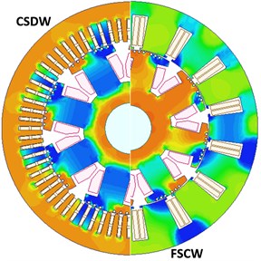
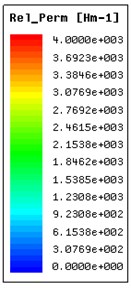
Fig. 5Relative permeability of the iron cores
a)
b)
Table 8Winding resistances and reactance
Parameters (Ω) | CSDW | FSCW |
Stator resistance | 0.291 | 0.306 |
Stator reactance | 4.57 | 27.38 |
D-axis reactance | 75.65 | 78.9 |
Q-axis reactance | 43.6 | 40.85 |
Field Resistance | 0.7 | 0.57 |
A reduction in the magnetic permeability of the iron paths is the immediate consequence of saturation. Fig. 5 shows, in a simplified manner, the variation of the stator and rotor iron permeability for the designed machines. As shown in Fig. 5, rotor pole relative permeability of the FSCW machine is higher than the CSDW machine. Therefore, saturation point of the FSCW machine’s iron core is increased owing to high flux leakages on the rotor pole. Thus, FSCW machine can be loaded more and also terminal voltage of the FSCW machine can be increased more according to CSDW machine. The FSCW generator does not require bigger cooling equipment because of its lower armature current density.
5. Conclusion
This study presents a detailed comparison between large FSCW and CSDW SPSGs for power generation applications in order to display the implementation of the FSCW method on large SPSGs. A 69Q8P CSDW SPSG and a 15Q8P FSCW SPSG were designed to compare their parameters and characteristics. A standard winding factor was developed by experimental combination of pitch and distribution factors using the large range of available space. After the required analysis, the obtained results can be summarized as below. FSCW SPSGs offer opportunities to minimize machine volume, mass and cost thanks to their short winding end turns and techniques for achieving high slot fill factors. Core and Eddy (stranded) losses are reduced, the relative permeability of the iron cores increased in generator poles, a higher efficiency was achieved without reducing the output power, and the CSDW machine becomes easier to maintain by designing it as FSCW machine through simplifying its complex structure.
The main conclusion of this study is that SPSMs can be designed to obtain lighter, cheaper and higher-efficiency SPSGs with simpler structures and poles with higher permeability without reducing the output power through the FSCW technique. A detailed explanation has been presented describing how the concentrated windings achieve this objective by increasing the phase inductance. Results presented in this paper open the door to further developing SPSG designs and these results are intended to provide useful guidelines for engineers faced with reducing the saturation of the generator poles without reducing the efficiency and optimal design of the machine.
References
-
Tessarolo A., Bassi C., Giulivo D. Time-stepping finite-element analysis of a 14-MVA salient-pole shipboard alternator for different damper winding design solutions. IEEE Trans. Ind. Electron., Vol. 59, Issue 6, 2012, p. 2524-2535.
-
Shima K., et al. Analysis of reduction effect on magnetic saturation in salient-pole synchronous machines by additional permanent magnets. Proc. of Int. Symp. on Electromag. Fields in Mechat., Electrical and Electronic Eng, Prague, p. 1-4.
-
Soong W. L., Miller T. J. E. Field weakening performance of brushless synchronous AC motor drives. IEE Proceedings-Electric Power Applications, Vol. 141, Issue 6, 1994, p. 331-340.
-
El-Refaie A. M. Fractional-slot concentrated-windings synchronous permanent magnet machines: opportunities and challenges. IEEE Transactions on Industrial Electronics, Vol. 57, Issue 1, 2010, p. 107-121.
-
El-Refaie A. M., Jahns T. M., Novotny D. W. Analysis of surface permanent magnet machines equipped with concentrated windings. IEEE Trans. Energy Convers., Vol. 21, Issue 1, 2006, p. 34-43.
-
Sen P. C. Principles of electric machines and power electronics. John Wiley & Sons Press, 2nd Ed., 1997, p. 569-581.
-
Krishnan R. Permanent magnet synchronous and brushless DC motor drives. Taylor & Francis Group, LLC, CRC Press, 2010, p. 127-132.
-
Chong L., Rahman M. F. Saliency ratio derivation and optimisation for an interior permanent magnet machine with concentrated windings using finite-element analysis. IET Electric Power Application, Vol. 4, Issue 4, 2010, p. 249-252.
-
Zhu L., Jiang S. Z., Zhu Z. Q., Chan C. C. Analytical methods for minimizing cogging torque in permanent-magnet machines. IEEE Trans. Magn., Vol. 45, Issue 4, 2009, p. 2023-2031.
-
Reddy P. B., Jahns T. M., El-Refaie A. M. Impact of winding layer number and slot/pole combination on AC armature losses of synchronous surface PM machines designed for wide constant-power speed range operation. IEEE Industry Applications Society Annual Meeting, Madison, WI, USA, 2008, p. 1-8.
-
Gündoğdu T. Kömürgöz G. Implementation of fractional slot concentrated winding technique in large salient-pole synchronous generators. IEEE Power Electronics and Machines in Wind Applications, 2012, p. 1-7.
-
Lipo T. A. Introduction to AC machine design: Wisconsin power electronics research center. University of Wisconsin-Madison, 2004.
-
Zhu Z. Q., Howe D. Winding inductances of brushless machines with surface-mounted magnets. Proc. International Electric Machines and Drives Conference, 1997, p. WB2/2.1-WB2/2.3.
-
Zhu Z. Q., Howe D. Instantaneous magnetic field distribution in brushless permanent magnet DC motors, Part II: armature-reaction field. IEEE Trans. Magn., Vol. 29, Issue 1, 1993, p. 136-142.
-
Gündoğdu T., Kömürgöz G. The design and comparison of salient pole and permanent magnet synchronous machines. 7th International Conference on Electrical and Electronics Engineering (ELECO’11), Bursa, Turkey, 2011, p. 1371-1375.
-
Gundogdu T., Komurgoz G. Technological and economical analysis of salient pole and permanent magnet synchronous machines designed for wind turbines. Journal of Magnetism and Magnetic Materials, Vol. 324, Issue 17, 2012, p. 2679-2686.
-
LME. 2013 (accessed 1/08/2013). http://www.lme.com.
-
IEEE recommended practices and requirements for harmonic control in electrical power systems. Standard, IEEE 519, New York, 1993.
