Abstract
The recovery efficiency of drilling fluid is directly affected by working performance of the vibration screen. Therefore, a newly dynamic vibration absorption system driven by different excitation frequencies is designed through double-frequency synchronization theory to improve the mechanical performance of screening equipment. Firstly, the differential equations of motion of vibration system are deduced by Lagrange method. Then, the theoretical conditions of the system implementing double-frequency synchronization are obtained based on asymptotic method, and stability criterion of the synchronization is revealed according to Routh-Hurwitz criterion. Subsequently, the effects of structure parameters on vibration isolation ability, synchronous state, and stability of synchronization are numerically discussed. Finally, the feasibility of the theoretical method and the obtained results is further verified by simulation and experiment. It is found that the vibration isolation and synchronization performance of the system is influenced by the motor parameters and system structure. The system has the best vibration isolation ability when ωm0=157 rad/s, which is considered as the best operating frequency of the present vibration system. Meanwhile, when the mass ratio κ between the high-frequency co-rotating rotor and the low-frequency co-rotating rotor is smaller, the absolute value of the stability coefficient Si is larger, and the stability phase difference is smaller, and the system is more stable. The present work can provide theoretical direction for the design of new screening equipment.
Highlights
- The mechanical modelling of a dynamic vibration absorption system driven by three co-rotating exciters was established.
- Asymptotic method was applied to the near-resonance system.
- The optimal operating frequency of the system during operation was revealed.
- The correctness of the theoretical derivation and numerical simulation was verified through experiments.
1. Introduction
With the development of synchronization theory, vibration synchronization technology has been widely used in machinery, biology, chemical industry, and other fields [1]-[4]. Self-synchronous vibrating screen is largely applied in material screening and mud filtration. Therefore, it is of great engineering significance to explore the synchronous mechanism of self-synchronous vibration system for the development of rotary screening machinery.
For synchronization of rotor system, towards the end of the century, Blekhman firstly proposed the direct motion separation method to study synchronization of the exciter mounted in a rigid frame [5], [6]. Subsequently, considering fluctuation of the velocity and phase of the rotor in vibration system, Wen introduced the disturbance parameter to greatly simplify mathematical treatment process of computing synchronization status [7], [8], which is also called average method of small parameters. The two research methods above are the basic methods commonly applied in the study of the fundamental frequency synchronization of vibration systems. With the deepening of research on synchronization, the improvement of vibration screen performance has become an urgent desire for scholars and engineers. For the nonlinear jump problem observed in the traditional vibration system, Balthazar et al. investigated synchronous behavior among multiple non-ideal exciters in vibration system through numerical analysis and simulation, and revealed the relationship between Sommerfeld effect and synchronization of the system [9]-[11]. Kovriguine et al. discussed the amplitude-frequency response and Sommerfeld effect of the vibration system driven by two exciters in the near-resonance region, and proved that the nonlinear coupling occurred between the elastic base and the unbalanced rotor. The result shows that the bifurcation oscillation phenomenon and Sommerfeld instability region of the vibrating system gradually disappeared as the increase of energy dissipation. The research has important engineering significance for reducing the working noise of vibration machinery and extending the life of equipment [12]. In order to improve screening efficiency, Zou et al. revealed double-frequency synchronization mechanism in far-resonance vibration system, and designed control strategy to improve stability of synchronization on the basis of sliding mode control method [13]-[15]. According to the above researches, high efficiency, high reliability and high intelligence are the design and development goals of screening device at present.
Unlike the traditional vibration isolation mode (i.e., isolation spring), the adverse effects such as low screening efficiency, vibration fatigue and structural failure caused by vibration can be greatly reduced in vibrating system with double rigid frames [16]-[18]. In engineering, many new types of vibration equipment with double rigid frames and same-frequency actuation have been designed and manufactured. Meanwhile, the vibration system driven by multi-frequencies has been proven to improve the working performance in some special industry fields. For example, in mineral separation, the double-frequency excitation can greatly improve the screening efficiency of the vibration screen under certain conditions [19], [20]. Therefore, the research and development of vibration system with double rigid frames and multi-frequency actuation is urgent.
In the previous literature, most studies focused on the fundamental frequency synchronization of the vibration system with double rigid frames or the dual-frequency synchronization of far-resonance system [13]-[21]. The multi-frequency synchronization of the double-rigid-frame system operating in the near-resonance region, however, is rarely studied except for Ref. [13]. The exploration of the stability problem of multifrequency synchronization in the near-resonance region is even rather limited. In Ref. [13], taking dynamical model of an anti‑resonance system with dual‑motor and double‑frequency actuation for example, synchronous mechanism of the system is studied by average method of small parameters, and synchronization state and vibration isolation performance are discussed numerically. However, there are still some shortcomings in the research work of Ref. [13]: (1) no experimental prototype is designed to verify the credibility of the theoretical research and the correctness of the obtained results; (2) the stability of the synchronization state, as crucial feature of the synchronization performance, is not analyzed numerically; (3) The solution process is complicated and the coupling term of the system is difficult to be eliminate.
In the process of solving the fundamental-frequency synchronization problem of vibration system, the direct motion separation method and average method of small parameters are the two most commonly used means. But in vibration system excited by dual-frequency, the process of solving synchronization is very complicated since a lot of coupling terms in balanced equation of the motor are eliminated difficultly. In this case, to solve the multi-frequency synchronization problem in far-resonance system, a mathematical analysis method called asymptotic method is proposed by Sergey et al. [22]. Based on Sergey’s study, Zhang et al. investigated the multi-cycle synchronization and stability of a vibration system with a single body in detail through theoretical, numerical and experimental methods [23], [24]. Therefore, in this paper, the asymptotic method is introduced to establish double-frequency synchronization theory of vibration system with double rigid frames operating in the near-resonance region. This method reasonably eliminates a large number of coupling terms in the equilibrium equations of the motor and simplifies the cumbersome process of calculating the synchronization problem of the system, and at the same time, uses computer simulation and experiments to validate the correctness of the asymptotic method in the solving process.
In the present work, taking dynamical model of a dynamic vibration absorption system with three co-rotating rotors (CRs) and double‑frequency actuation as an example, the vibration isolation performance and double-frequency synchronization are studied in detail through theoretical, numerical, simulation and experimental methods. the research results will provide theoretical guidance for the design of new vibrating equipment with double rigid frames and multi-frequency actuation.
2. Differential equation of motion
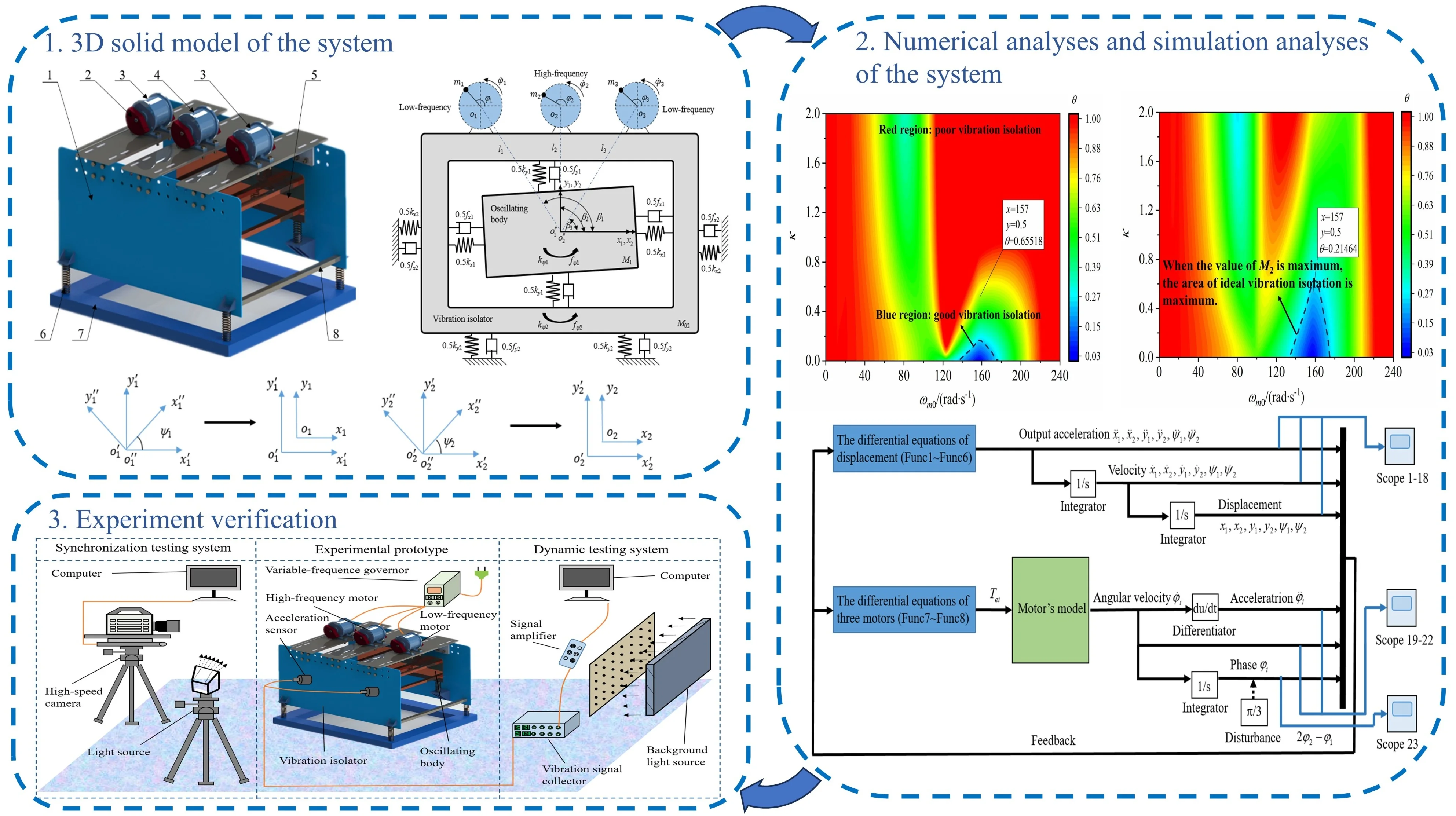
According to the 3D solid model of dynamic vibration absorption system with three CRs and double‑frequency actuation shown in Fig. 1(a), the simplified dynamic model of the vibrating system is illustrated in Fig. 1(b). The vibration isolator (VI) M02is connected to oscillating body (OB) M1and foundation through compression springs with stiffness coefficients kxi(N/m), kyi (N/m) andkψi (N‧m/rad) (i=1,2).fxi(N‧s/m), fyi(N‧s/m) and fψi(N‧s‧m/rad) (i=1,2) are damping coefficients of the corresponding springs. Three CRs mi, separately driven by three identical motors with different supply frequencies, are fixedly mounted on VI. Based on the center-of-gravity positions of the vibrating device, the coordinate system o''ix''iyi'' is established to calculate the differential motion equation of the CRs. Therefore, the position of the CRs in coordinate system o''ix''iyi'' can be described by position parameters li (m), setting angle βi (rad), rotational radius of the CRs ri (m) and phase angle φi, i.e.:
Fig. 13D solid model of the system: 1 – the VI; 2 – the CRs; 3 – low-frequency motor; 4 – high-frequency motor; 5 – the OB; 6 – isolation spring; 7 – foundation support; 8 – steel frame
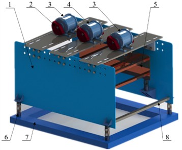
a) 3D solid model of the system
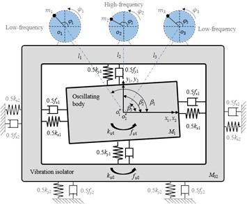
b) Simplified dynamic model of the vibration system
c) Coordinate transformation method
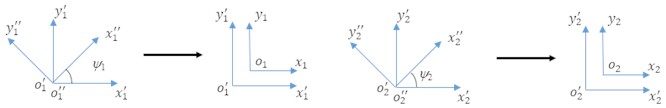
In order to accurately describe the kinetic energy of the system, the position vector of the CRs in fixed-coordinate system oixiyiis obtained by using a coordinate transformation method combining Park’s transformation and translation transformation, as shown in Fig. 1(c). The mathematical model of the coordinate transformation can be described as:
where Φ0is represented as the displacement vector of the VI. Substituting Eq. (2) into Eq. (1), the position vector Φiof the CRs in coordinate system oixiyican be rewritten as:
The kinetic energy of the vibration system can be expressed as:
The potential energy of the vibration system is expressed by:
The energy dissipation of the system is described as:
where, ˙•=dΔ/dt, ¨•=d2Δ/dt2; J0i (kg‧m2) is the rotational inertia of the CRs (i=1,2,3) (J0i=mir2); the rotational inertia of the OB and VI is described as Ji (Ji=Mile2); ψ1and ψ2 are represented as the oscillation angle of the OB and VI, respectively; fi is represented as the damping coefficient of the motors i. To calculate differential equation of motion of the vibration system, a vector e=[x1,x2,y1,y2,ψ1,ψ2,φ1,φ2] is chosen as the generalized coordinates. Therefore, Lagrange equation can be expressed as:
In light of Lagrange method, the motion differential equations of the vibrating system are established as follows:
with M2=M02+m1+m2+m3; Teimeans output torque of the motors.
3. Dynamic behaviors of the vibrating system
Since the damping of the vibration system is very small relative to the other forces on the system during normal operation, and the speed fluctuation of the CRs is very small, and the change in angular acceleration has less effect on the main behavior of the system (e.g., displacement and velocity), the terms related to the damping of the compression springs and the angular acceleration ¨φi can be omitted from Eq. (8), which will simplify the subsequent solution process and make it easier to solve for the system. Some parameters are introduced as follows:
It can be noticed from Eq. (8) that the vibrating system is a second-order linear system with mutually coupled degrees of freedom (DOF). Inserting Eq. (9) into Eq. (8) and decoupling the motion differential equations of the VI and OB, the steady-state solution of the VI and OB in all DOFs can be obtained:
with
c1j1=c3j1=n2lj2,c2j1=n2hj2,c1j2=c3j2=n2lj2(1-n2lj1),c2j2=n2hj2(1-n2hj1),
a1j=a3j=(1-n2lj1)(1-n2lj2)-μ12n2lj2,a2j=(1-n2hj1)(1-n2hj2)-μ12n2hj2,
dij=bij=0,j=x,y,ψ,i=1,2,3,
where parameters μij1 and μij2 are amplitude amplification factors of the forced vibration response. Meanwhile, in order to master vibration isolation effect during the operation of vibrating screen, vibration absorption coefficient ϑ, the ratio between the amplitude of the VI in y1 DOF and the amplitude of the OB in y2 DOF, is represented as vibration isolation ability of the system in the vertical direction:
4. Double-frequency synchronization of the three CRs
In this section, double-frequency synchronization relationship of the three CRs is further concerned. According to Eq. (3), ¨xi, ¨yi and ¨ψi can be acquired after the differentiation process. Considering Ref. [8], substituting the parameters above into the last two formulae of Eq. (8), the approximate expressions regarding the angular acceleration ¨φj (j=1,2) of each CR can be described as:
with
bi=μiy2-μix22,Aij=-μiψ2rlirlj2κ2j,
T(1)j-2ρ(1)j˙φj=fjJ0jωm0,T(2)j-2ρ(2)j˙φj=TejJ0jω2m02,ε=m1M2,j=1,2,3
where the mass of the CR1, m1, is much less than M. Therefore, small parameter ε, ratio of m1 to M, is introduced in Eq. (10) to calculate approximate expressions. In order to reveal double-frequency synchronization relationship between CRs, instantaneous phase of the CRs can be expressed as:
where, Δj is defined as the fluctuation coefficient when the phase changes; ωm0 is considered as the lowest operating frequency of the system; Instantaneous phase φj, consisting of linearly increasing term (i.e., σjτ) and fluctuation coefficient term (i.e., Δj), is gradually increased during the steady operation process of the system. Compared with phase φj, Δj is a slow-changing parameter. Substituting Eq. (13) into Eq. (12), the expression related to ¨Δj can be got:
Then, the expression related to ¨Δj can be rewritten as:
with χ-ij=(σj-σi)τ+Δj-Δi-βj+βi, χ+ij=(σj+σi)τ+Δj+Δi-βj-βi.
After the operations above, the approximate expression to carry out synchronization between the CRs is obtained, as seen in Eq. (15). In order to further study phase difference of the CRs, according to the asymptotic method, we rearrange Eq. (6) into Bogoliubov standard form by:
Differentiating Eq. (15) with respect to τ, the expression ¨Δi can be obtained, and substituting the results into Eq. (17), the expression related to ˙vj can be described as:
˙vj=√ε{T(1)j-2ρ(1)jσj+kjsin(σjτ+Δj)
-∑3i=1σ2iλij(aisin(χ+ij+βj+βi))+bisin(χ-ij+βj-βi)}-3Aij(sinχ+ij-sinχ-ij))
+ε{-2ρ(1)jvj-∑3i=12σiviλij(aisin(χ+ij+βj+βi)+bisin(χ-ij+βj-βi))}
+√ε3{T(2)j-2ρ(2)jσj-∑3i=1λijv2i(aisin(χ+ij+βj+βi)+bisin(χ-ij+βj-βi))
-∑3i=1λij{T(1)i-2ρ(1)iσi+kisin(σiτ+Δi)-∑3r=1σ2rλri{arsin(χ+ri+βi+βr))
+brsin(χ-ri+βi-βr)-Ari(sinχ+ri-sinχ-ri)}
×(aicos(χ+ij+βj+βi)+bicos(χ-ij+βj-βi)+Aij(cosχ+ij+cosχ-ij))}}+ε2⋯,
where, the expression related to ˙vj is proportional to small parameter √ε. Therefore, integral parameter vj is a slow-changing parameter. According to average method, parameter vj can be approximately expressed as a superposition of an approximate linear term Ωj and small oscillation items, as follows:
-∑3i=1σ2iλij(-aiqijcos(χ+ij+βj+βi)-bipijcos(χ-ij+βj-βi)
+Aij(qijcosχ+ij-pijcosχ-ij))},
with
Substituting Eq. (18) into Eq. (17), then integrating them in region , the averaged differential equation can be obtained. It should be noted that the value of the small oscillation items related to on is very small after the treatment above. Hence, parameter can be represented as after the integration. and are regarded as constants during the process of averaging. The averaged balanced equation of the motors can be arranged as:
where
The synchronization among the CRs can be implemented when and . The rotational speed ratio between CR 1 and CR 3 is equal to 1:1 when . Therefore, same-frequency synchronization of the vibration system is carried out when . In this case, the phase difference between CR 1 and CR 3 can be written as:
The excitation motors 1 and 3 are powered by the same power source. In this case, Eq. (19) can be described as:
The torque of the motors is balanced when vibration system operates in synchronous state, i.e.,:
According to Eqs. (21-22), the same-frequency synchronization condition between the CR 1 and CR 3 can be expressed as:
The double-frequency synchronization is implemented when , . Thus, the phase difference among the CRs can be written as:
where, the excitation motor 2 is powered by a separate high-frequency power supply. Thus, the formula related to in Eq. (22) can be described as:
The mean value of the fluctuation of the system can be regarded as zero when motors operating in synchronous state, i.e.,:
Introducing Eq. (26) into Eq. (25), the condition among CRs implementing double-frequency synchronization can be expressed as:
Multiple synchronization solutions can be obtained by calculation from Eq. (26) and Eq. (27). However, some of them are stable. In order to find stable synchronization solutions, micro-disturbance and to and are applied here, respectively, i.e.,:
Substituting Eq. (28) into Eq. (27), disturbance equations of the vibrating system can be described as:
Rearranging Eq. (29), the balanced equation related to disturbance can be obtained as:
Setting as the eigenvalue of the Eq. (30), the corresponding characteristic equations can be written as:
In light of Routh-Hurwitz criterion, the real part of the all roots in Eq. (31) must be negative to guarantee the existence of stable solutions. Therefore, the stability condition of double-frequency synchronization of the vibrating system can be expressed as follows:
where, is stability coefficient for fundamental frequency synchronization, and is the stability coefficient for double-frequency synchronization. According to the simplified physical model of the vibration system, the identical low-frequency motors (motor 1 and motor 3) are symmetrically installed on the VI. Therefore, some parameters of the motors can be described as:
From Eq. (9), parameters , , , are positive. Introducing Eq. (33) into Eq. (32), the stability condition of double-frequency synchronization can be rewritten as:
5. Numerical analyses based on the above theoretical results
According to engineering practice, some numerical discussions on vibration absorption performance and synchronous stability of the vibration system are given in this section based on the theoretical results above. The nominal parameters of the motor are assigned as follows: 380 V, 0.12 kW, 50 Hz, 2-pole, rated velocity 3000 r/min, stator resistance Ω, rotor resistance Ω, stator inductance H, rotor inductance H, the mutual inductance H. Theoretical analysis and experimental studies have shown that the processing capacity of vibrating screen increases with the increase of amplitude and excitation frequency, but the amplitude is not much affected by the excitation frequency after moving away from the resonance region. In actual engineering application, the amplitude is generally taken as 2-5 mm, and the stiffness coefficient and the damping coefficient have a significant relationship with the amplitude. Therefore, the structural parameters of the system are detailed in Table 1.
Table 1The structure parameters of the vibration system
Oscillating body | Vibration isolator | Eccentric rotors |
50kg | 35-80 kg | 1-4 kg |
47326 N/m | 47326N/m | 1-2 kg |
1232450 N/m | 47326N/m | 0.05 m |
19719N‧m/rad | 19719N‧m/rad | 0-1 m |
60N‧s/m | 60 N‧s/m | or or |
198N‧s/m | 0-314 N‧s/m | |
25N‧s‧m/rad | 25 N‧s‧m/rad | – |
10kg‧m2 | 10 kg‧m2 | – |
5.1. Vibration isolation ability
Vibration isolation ability, as a critical index of vibration system performance, is measured by vibration absorption coefficient . In light of Eq. (11), coefficient is mainly influenced by mass ratio , lowest excitation frequency and mass of the VI if the other structure parameters of the vibration system are assigned in Table 1, and vibration isolation of the system is carried out when . Moreover, it can be seen from Eq. (11) that the smaller the coefficient , the better the vibration isolation performance. Taking parameters and as the independent variables, the variation laws of vibration absorption coefficient when 35 kg, 50 kg, 65 kg and 80 kg is plotted in Fig. 2(a)-(d), respectively. As shown in Fig. 2, the red region indicates that vibration isolation is absent, while the blue area means that the vibration isolation performance is ideal. In Fig. 2, the region for implementing ideal vibration isolation is a triangular region centered at point (157, 0), and the farther away from the center, the larger the coefficient . Therefore, the vibration isolation performance is the best when the lowest operating frequency is equal to the natural frequency of the OB. In this case, 157 rad/s is considered as the optimal operating frequency of the vibration system. Meanwhile, by comparing Fig. 2(a)-(c), the larger the value of , the larger the region for implementing ideal vibration isolation.
Fig. 2The vibration absorption coefficient
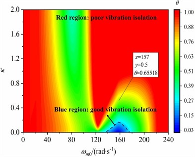
a)35 kg
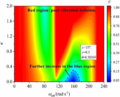
b)50 kg
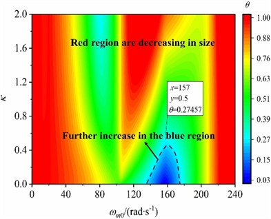
c)65 kg
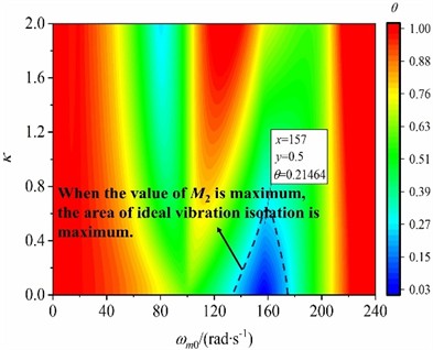
d) 80 kg
5.2. Stable phase difference
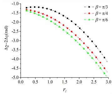
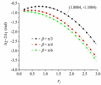
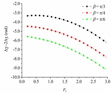
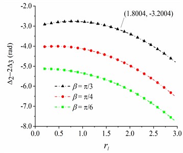
The phase difference among the CRs is the most important parameter to measure the synchronization state of the system. From Eq. (23) and Eq. (27), the phase difference among the CRs can be calculated. When the stable double-frequency synchronization is carried out in the vibration system, the phase difference can be obtained according to Eq. (34). It can be observed from theoretical derivation in section 4 that the stable phase difference is affected by the mass ratio of the CRs and the installation position of excitation motors (i.e., installation angle and position parameters ). What is noteworthy is that the stable phase difference between same-frequency CRs can be calculated by the stable phase difference between double-frequency CRs (). Therefore, the stable phase difference between same-frequency CRs is less discussed in the section. When and , , the values of and are slightly changed at first and then gradually decrease with the increase of parameter , as seen in Fig. 3 and Fig. 4. Meanwhile, as shown in Fig. 3 and Fig. 4, the smaller the mass ratio , the smaller the stable phase differences and . Stable phase differences of and when are greater than those when , and stable phase difference is maximal when .
Fig. 3The phase difference between CRs 1 and 2
a)0.04
b)0.06, 0.03
Fig. 4The phase difference between CRs 2 and 3
a) 0.04
b) 0.06, 0.03
5.3. Stability characteristics
In order to grasp the stability characteristics of the vibration system under the fundamental frequency synchronization and double-frequency synchronization, taking parameters and the mass ratio between the high-frequency CR and the low-frequency CR as variables, the variation laws of the stability coefficient are numerically discussed. As shown in Fig. 5(a) and (b), stability coefficient for fundamental frequency synchronization and stability coefficient for double-frequency synchronization are negative definite as changes, which reveals that the system will be in a monostable state in this case. Meanwhile, the values of gradually decrease and remains substantially unchanged with the increase of . The absolute value of is greater than that of . Therefore, the stability for fundamental frequency synchronization is greater than the stability for double-frequency synchronization in the system. Moreover, the smaller the mass ratio between the high-frequency CR and the low-frequency CR, the greater the absolute value of stability coefficient. It is shown that choosing a reasonable mass of high-frequency CR and low-frequency CR in the system helps to improve the stability of the system. The analysis of the stability of the synchronous state of the system makes up for the theoretical deficiencies of Ref. [13] and helps to make a reasonable choice of rotor mass and installation parameters in the future design of the prototype.
6. Simulation analyses of the system
In this section, the electromechanical coupling model of the vibration system is established to verify the numerical analyses above. The motor performance and the structure parameters of the system are consistent with the parameters in Section 5.
Fig. 5Stability coefficient S1 and S2
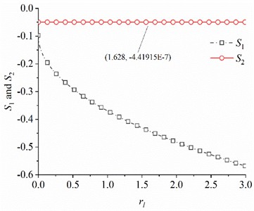
a)0.04, 0.04
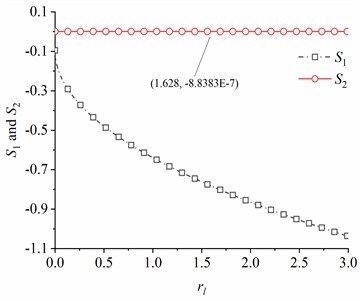
b) 0.06, 0.03
6.1. Electromechanical coupling model
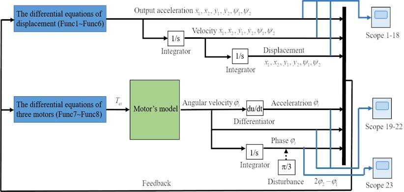
The schematic diagram of the electro-mechanical coupled model is plotted based on Runge-Kutta method, as shown in Fig. 6. In the procedure of simulation, the acceleration of the VB and VI in each DOF is the output of the mechanical system. Thus, the displacements and velocities of the rigid frames can be calculated by an integrator. Then, taking these numerical values back to the torque equilibrium equation of the motors, the dynamic equilibrium between the coupling torque and the loading torque can be achieved by adding a motor module. According to the dynamic equation of the vibration system, the angular velocity of the motor module is output. Therefore, the acceleration and phase of the CRs can be obtained through differentiator and integrator, and the data will be fed back to the dynamic equations of the system. It is obvious that the electromechanical coupling model is a closed-loop system. Moreover, a phase disturbance is added to the motor 3 to test the stability of the system, as seen in Fig. 6. Meanwhile, the blue cabling part on the right side of Fig. 6 is an observing system, and the output quantity of the closed-loop system during simulation can be observed by an oscilloscope.
Fig. 6The electromechanical coupling model of the vibration system
6.2. Simulation results for rad, 80 kg, 3 kg, 1.5 kg, 1.8
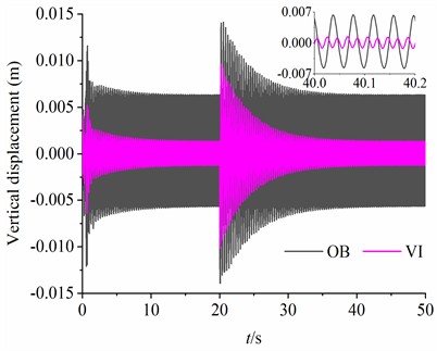
In this section, considering rad, 80 kg, kg, kg, , the simulation results are illustrated in Fig. 7. It can be observed from Fig. 7(a) that the rotational velocity of motor 2 is stabilized at 314 rad/s. The rotational velocities of the motors 1 and 3 are maintained at 157 rad/s by reducing the frequency of the power supply. Besides, the output electromagnetic torques of three motors are kept within 6 N·m during simulation analyses, as seen in Fig. 7(b). What is noteworthy is that the fluctuation ranges of the rotational velocity and output electromagnetic torque of the low-frequency motor (motors 1 and 3) are larger than those of the high-frequency motor (motor 2). As shown in Fig. 7(c), the stable phase difference between CRs with same frequency is stabilized at –1.05 rad, and the stable phase differences between CRs with different frequency and are –1.10 (rad, –1.10 = –114.2 + 2 ×18) and –3.20 (rad, –3.20 = –116.3 + 2 ×18), respectively. From Fig. 7(d), the oscillating angle of the vibration system is very small. Meanwhile, the displacement amplitudes of the VI in the horizontal and vertical directions are smaller than the OB, as shown in Fig. 7(e) and (f). It should be noticed that the amplitude of the VI (1.35×10⁻³ m) in DOF is only 21.43 % of the OB (6.30×10⁻³ m) in DOF. In this case, the ideal vibration isolation is implemented. In order to test the stability of the synchronous operation of the system, a phase disturbance of is added to the motor 3 at the 20th second of the simulation start. As seen in Fig. 7, a short-term fluctuation is observed in the dynamic responses of the vibration system when disturbance is added. Later, the system quickly returns to the previous states. Therefore, the synchronous stability of the vibration system is very strong.
Fig. 7The simulation results when β=π/3 rad, M2=80 kg, m1=m3=3 kg, m2=1.5 kg, rl=1.8
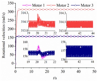
a) Rotational velocities of the motors
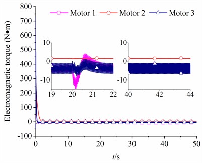
b) Electromagnetic torque
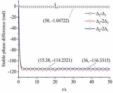
c) Stable phase difference
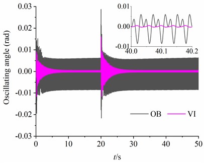
d) Oscillating angle of the OB and VI
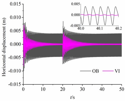
e) Displacements in and DOFs
f) Displacements in and DOFs
7. Experiment verification
In order to verify the practicality of the double-frequency synchronization theory of the vibration absorption system in the oil drilling engineering, an experimental prototype is established, and a test scheme for dynamic response and synchronization characteristics is detailed given. Meanwhile, the motor performance parameters and the structure parameters of the vibration system are consistent with the parameters in the simulation.
7.1. Test scheme of the experimental prototype
The diagram of the test scheme consists of the synchronous test system, the experimental prototype, and the dynamic characteristic test system, as shown in Fig. 8. What is noteworthy is that the performance parameters such as slip rate, magnetic flux, etc., are different if the types of induction motors are different. Therefore, double-frequency synchronization among the CRs is hard to accurately carry out.
Fig. 8The diagram of the test scheme
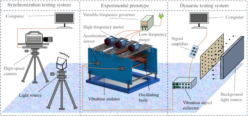
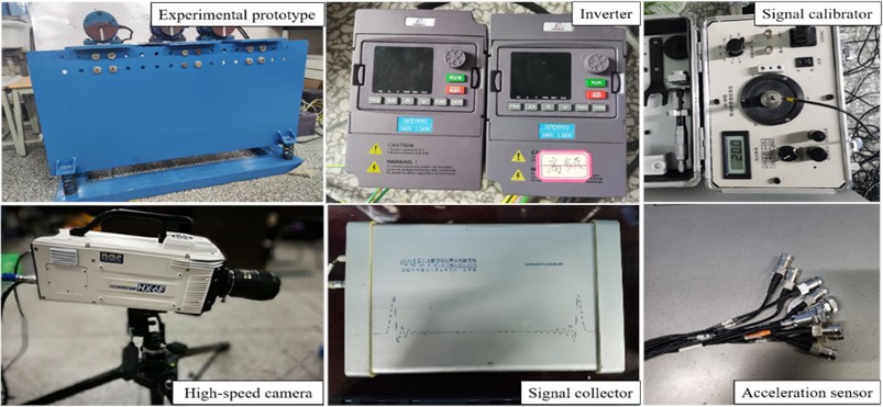
In order to reduce the experimental error caused by the type of excitation motor, the type of excitation motor used in the experiment is identical (model: YZS-1.5-2). In addition, the power frequency of the high-frequency excitation motor is adjusted by the frequency converter governor to reduce its rotational speed to about 1500 r/min to realize the demand of the system’s double-frequency relationship. The experimental prototype and the main testing instruments are listed in Fig. 9. In the process of dynamic characteristics testing, the sensor calibrator is used to calibrate the sensitivity of the acceleration sensor. Later, the acceleration values of VI and OB in the vertical and horizontal directions are detected by the acceleration sensor. Then, a dynamic signal acquisition and analysis system is used to integrate the data collected by the signal collector (e.g., acceleration signal) and pass it to the analysis system to obtain the vibration system displacement response. Finally, the displacement response of the vibration system can be calculated by integrating the acceleration signal. On the other hand, a high-speed camera is used to accurately record the instantaneous phase of the CRs during the experiment. The use of high-speed cameras minimizes errors in the recording of instantaneous phase differences of the CRs. Then, the instantaneous phase information at different times is transmitted to the computer to calculate the phase difference related to time. Through the experimental scheme above, the synchronization state and dynamic response of the experimental prototype during operation can be accurately recorded, which can provide experimental verification for the double-frequency synchronization theory in the vibration absorption system.
Fig. 9Experimental prototype of and the testing instruments
7.2. Dynamic response of the vibration system during the experiment
When the system runs stably, the acceleration responses of the VI and OB in the vertical and horizontal directions detected by the acceleration sensor are illustrated in Fig. 10(a)-(b), respectively. The maximum amplitudes of the acceleration responses of the OB in the horizontal and vertical directions are 50.21 m/s2 and 51.98 m/s2, respectively. The maximum amplitudes of the acceleration responses of the VI in and DOFs are 4.86 m/s2 and 4.87 m/s2, respectively. The isolation capability of the system is the critical index to measure the performance of the vibration system. Therefore, the displacement responses of the OB and VI in the vertical and horizontal directions are calculated by quadratically integrating the acceleration signal, as shown in Fig. 10(c)-(d). In particular, the amplitude of the VI (1.35×10⁻³ m) in DOF is only 21.43 % of that of the OB (6.30×10⁻³ m) in DOF. The vibration isolation capacity of the system is ideal at this point. Compared with the previous research content, this experiment not only clarifies the specific vibration isolation capability of the system, but also clarifies the detailed parameter selection and structural design for the fabrication of the actual prototype of the subsequent engineering.
Fig. 10The dynamic response of the vibration system when β=π/3 rad, M2=80 kg, m1=m3=3 kg, m2=1.5 kg, rl= 1.8
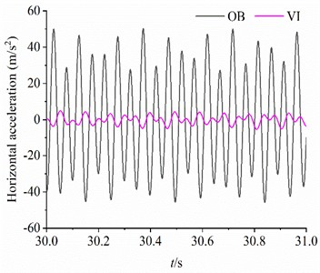
a) Horizontal acceleration of the OB and VI
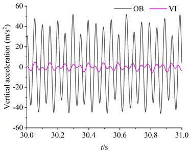
b) Vertical acceleration of the OB and VI
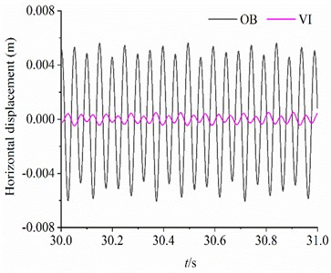
c) Horizontal displacement of the OB and VI
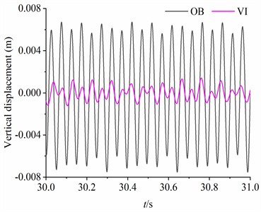
d) Vertical displacement of the OB and VI
7.3. Stable synchronization state of the CRs during the experiment
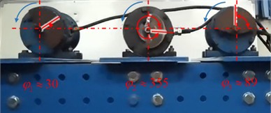
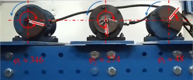
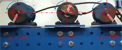
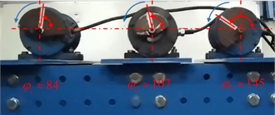
During the steady synchronous rotation of the CRs, the instantaneous state of the CRs is accurately recorded by a high-speed camera at multiple times, as illustrated in Fig. 11. According to Eq. (24), the instantaneous phase difference among the CRs can be obtained. The experimental results show that the stable phase differences of the three CRs are maintained at (–1.13 rad, –1.01 rad), (–3.19 rad, –3.09 rad) and (–1.08 rad, –1.03 rad), respectively. Therefore, the phase differences among CRs all fluctuate within a small range around the theoretical value.
7.4. Results comparison
In this section, the stable phase difference among the three CRs and the vibration isolation coefficient in the numerical analysis, simulation analysis and experimental verification are listed in Table 2. The comparison results show that the phase difference and the coefficient in simulation are consistent with the numerical analysis. Meanwhile, the values of the stable phase difference measured in the experiments are close to the theoretical value, which indicates that measurement errors are unavoidable during the experiment. The main reasons for the experimental errors can be summarized as follows: (1) manufacturing defects of the experimental equipment, such as uneven distribution of the system mass and spring stiffness errors, leading to uneven motor loads; (2) the actual performance parameters of the excitation motor are affected by voltage fluctuations, ambient temperature and humidity, and even if the two motors are of the same model, the actual electromagnetic output torque is not exactly the same due to the manufacturing and installation errors; (3) Inaccurate measurement positions of sensors and high-speed camera equipment lead to errors in the recorded dynamic response and synchronous phase. Although the experimental results deviate slightly from the theoretical values, the error value is very small, which also proves the practicality of the synchronization theory.
Fig. 11Stable synchronization state of the CRs
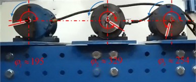
a) –61° (–1.06 rad), –179° (–3.12 rad), –59° (–1.03 rad)
b)–65° (–1.13 rad), –181° (–3.16 rad), –181° (–3.16 rad)
c)–58° (–1.01 rad), –182° (–3.18 rad), –62° (–1.08 rad)
d)–63° (–1.10 rad), –181° (–3.16 rad), –59° (–1.03 rad)
e) –61° (–1.06 rad), –183° (–3.19 rad), –61° (–1.06 rad)
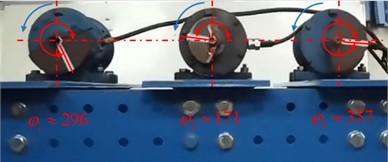
f) –61° (–1.06 rad), –183° (–3.19 rad), –61° (–1.06 rad)
Table 2Results comparison of the numerical analysis, simulation and experiment
– | Numerical analysis | Simulation | Experiment |
0.214 | 0.214 | 0.214 | |
(rad) | –1.05 | –1.05 | –1.13- –1.01 |
(rad) | –1.10 | –1.10 | –1.08- –1.03 |
(rad) | –3.20 | –3.20 | –3.19- –3.09 |
8. Conclusions
In order to improve the mechanical performance of the screening equipment, the double-frequency synchronization theory of a dynamic vibration absorption system with three CRs and double‑frequency actuation is established based on the asymptotic method. Some conclusions are obtained as follows:
1) Asymptotic method is applied to the near-resonance system, which provides a new way of solving the multi-frequency synchronization of the near-resonance system, and provides reference data for the design of a new high-efficiency vibration system.
2) The vibration isolation performance of the system is affected by motor and structure parameters of the system. When is operating at the optimal operating frequency of the vibration system (157 rad/s), the vibration isolation effect of the system is better. In addition, the vibration isolation capability was verified through vibration system simulation analysis and experimental tests.
3) The state of synchronization between the eccentric rotors is affected by the installation position of the excitation motor and the mass ratio of the eccentric rotors. Meanwhile, the larger the mass ratio between the double-frequency CRs and the installation angle of motor , the smaller the stable phase difference between double-frequency CRs, and the state of system synchronization is more sensitive to changes in installation distance.
4) The stability of fundamental frequency synchronization is greater than that of double-frequency synchronization in the vibration system. Moreover, the smaller the mass ratio between the high-frequency CR and the low-frequency CR, the greater the absolute value of stability coefficient.
References
-
A. E. Shokhin, K. V. Krestnikovskii, and A. N. Nikiforov, “On self-synchronization of inertial vibration exciters in a vibroimpact three-mass system,” in IOP Conference Series: Materials Science and Engineering, Vol. 1129, No. 1, p. 012041, Apr. 2021, https://doi.org/10.1088/1757-899x/1129/1/012041
-
S. A. Plotnikov and A. L. Fradkov, “Synchronization of nonlinearly coupled networks based on circle criterion,” Chaos: An Interdisciplinary Journal of Nonlinear Science, Vol. 31, No. 10, p. 10311, Oct. 2021, https://doi.org/10.1063/5.0055814
-
R. Al Mizan and M. A. Islam, “Synchronization of thermal properties and constituents in Nanocomposite: Manufacturing, characterization, adjustable properties,” Journal of Applied Polymer Science, Vol. 138, No. 12, p. 50056, Mar. 2021, https://doi.org/10.1002/app.50056
-
E. I. Pocoma Copa, F. Quitin, L. Vandendorpe, D. Philippe, and F. Horlin, “Self-Synchronization Based Localization of a Time-Misaligned Transmitter in Cellular Networks,” IEEE Transactions on Vehicular Technology, Vol. 71, No. 4, pp. 4102–4115, Apr. 2022, https://doi.org/10.1109/tvt.2022.3148532
-
I. I. Blekhman, Synchronization in Science and Technology. New York: ASME Press, 1988.
-
I. I. Blekhman, Vibrational Mechanics. Singapore: World Scientific, 2011.
-
B. C. Wen, H. Zhang, S. Y. Liu, Q. He, and C. Y. Zhao, Theory and Techniques of Vibrating Machinery and Their Applications. Beijing: Science Press, 2010.
-
B. C. Wen, J. Fan, C. Y. Zhao, and W. L. Xiong, Vibratory Synchronization and Controlled Synchronization in Engineering. Beijing: Science Press, 2009.
-
J. M. Balthazar, J. L. P. Felix, and R. M. Brasil, “Some comments on the numerical simulation of self-synchronization of four non-ideal exciters,” Applied Mathematics and Computation, Vol. 164, No. 2, pp. 615–625, May 2005, https://doi.org/10.1016/j.amc.2004.06.010
-
J. M. Balthazar, J. L. P. Felix, and R. M. L. R. F. Brasil, “Short comments on self-synchronization of two non-ideal sources supported by a flexible portal frame structure,” Journal of Vibration and Control, Vol. 10, No. 12, pp. 1739–1748, Dec. 2004, https://doi.org/10.1177/1077546304041754
-
J. L. P. Felix and J. M. Balthazar, “Comments on a nonlinear and nonideal electromechanical damping vibration absorber, Sommerfeld effect and energy transfer,” Nonlinear Dynamics, Vol. 55, No. 1-2, pp. 1–11, Feb. 2008, https://doi.org/10.1007/s11071-008-9340-8
-
D. A. Kovriguine, “Synchronization and sommerfeld effect as typical resonant patterns,” Archive of Applied Mechanics, Vol. 82, No. 5, pp. 591–604, Jul. 2011, https://doi.org/10.1007/s00419-011-0574-4
-
M. Zou, P. Fang, Y. Hou, G. Chai, and J. Chen, “Self-synchronization theory of tri-motor excitation with double-frequency in far resonance system,” Proceedings of the Institution of Mechanical Engineers, Part C: Journal of Mechanical Engineering Science, Vol. 234, No. 16, pp. 3166–3184, Mar. 2020, https://doi.org/10.1177/0954406220913584
-
M. Zou, P. Fang, Y. Hou, and H. Peng, “Investigation on multiple-frequency synchronization experiment of vibration system with dual-rotor actuation,” Mechanical Systems and Signal Processing, Vol. 164, p. 108261, Feb. 2022, https://doi.org/10.1016/j.ymssp.2021.108261
-
M. Zou, P. Fang, Y. Hou, Y. Wang, D. Hou, and H. Peng, “Synchronization analysis of two eccentric rotors with double-frequency excitation considering sliding mode control,” Communications in Nonlinear Science and Numerical Simulation, Vol. 92, p. 105458, Jan. 2021, https://doi.org/10.1016/j.cnsns.2020.105458
-
H. Peng, Y. Hou, P. Fang, M. Zou, and Z. Zhang, “Synchronization analysis of the anti-resonance system with three exciters,” Applied Mathematical Modelling, Vol. 97, pp. 96–112, Sep. 2021, https://doi.org/10.1016/j.apm.2021.03.055
-
X. Zhang, Z. Wang, C. Li, and J. Xu, “Comments on the stability of the synchronous states of three vibrators in a vibrating system with two rigid frames,” Journal of Mechanical Science and Technology, Vol. 33, No. 10, pp. 4659–4672, Oct. 2019, https://doi.org/10.1007/s12206-019-0909-6
-
Y. Hou, H. Peng, P. Fang, and M. Zou, “Synchronous characteristic of three homodromy motors in vibrating isolation system,” Journal of Mechanical Science and Technology, Vol. 35, No. 1, pp. 45–60, Jan. 2021, https://doi.org/10.1007/s12206-020-1204-2
-
R. Modrzewski and P. Wodzinski, “Grained material classification on a double frequency screen,” Physicochemical Problems of Mineral Processing, Vol. 46, No. 46, pp. 5–12, 2011.
-
R. Modrzewski and P. Wodzinski, “Screens for segregation of mineral waste,” Physicochemical Problems of Mineral Processing, Vol. 47, No. 47, pp. 267–274, 2011.
-
X. Li and T. Shen, “Dynamic performance analysis of nonlinear anti-resonance vibrating machine with the fluctuation of material mass,” Journal of Vibroengineering, Vol. 18, No. 2, pp. 978–988, Mar. 2016, https://doi.org/10.21595/jve.2016.16559
-
S. Eremeykin, G. Panovko, and A. Shokhin, “Features of dynamics of mechanical system with self-synchronizing vibroexciters near resonance,” Journal of Vibroengineering, Vol. 19, No. 7, pp. 4911–4920, Nov. 2017, https://doi.org/10.21595/jve.2017.19313
-
X. Zhang, X. Zhang, C. Zhang, Z. Wang, and B. Wen, “Double and triple-frequency synchronization and their stable states of the two co-rotating exciters in a vibrating mechanical system,” Mechanical Systems and Signal Processing, Vol. 154, p. 107555, Jun. 2021, https://doi.org/10.1016/j.ymssp.2020.107555
-
X. Zhang et al., “Theoretical, numerical and experimental studies on multi-cycle synchronization of two pairs of reversed rotating exciters,” Mechanical Systems and Signal Processing, Vol. 167, p. 108501, Mar. 2022, https://doi.org/10.1016/j.ymssp.2021.108501
About this article

This work was supported by the Chengdu International Science and Technology Cooperation Project [Grant number 2021-GH02-00083-HZ]; the Scientific Research Fund for Graduate Students of Southwest Petroleum University [Grant number 2021CXYB03]; and the Sichuan Science and technology program [Grant number 2021JDRC0093].
The datasets generated during and/or analyzed during the current study are available from the corresponding author on reasonable request.
Pan Fang: conceptualization, writing-review and editing; Weiming Zhu: methodology, writing-original draft preparation; Yongjun Hou: funding acquisition, resources; Dong Xiao: software, supervision, validation, visualization.
The authors declare that they have no conflict of interest.
