Abstract
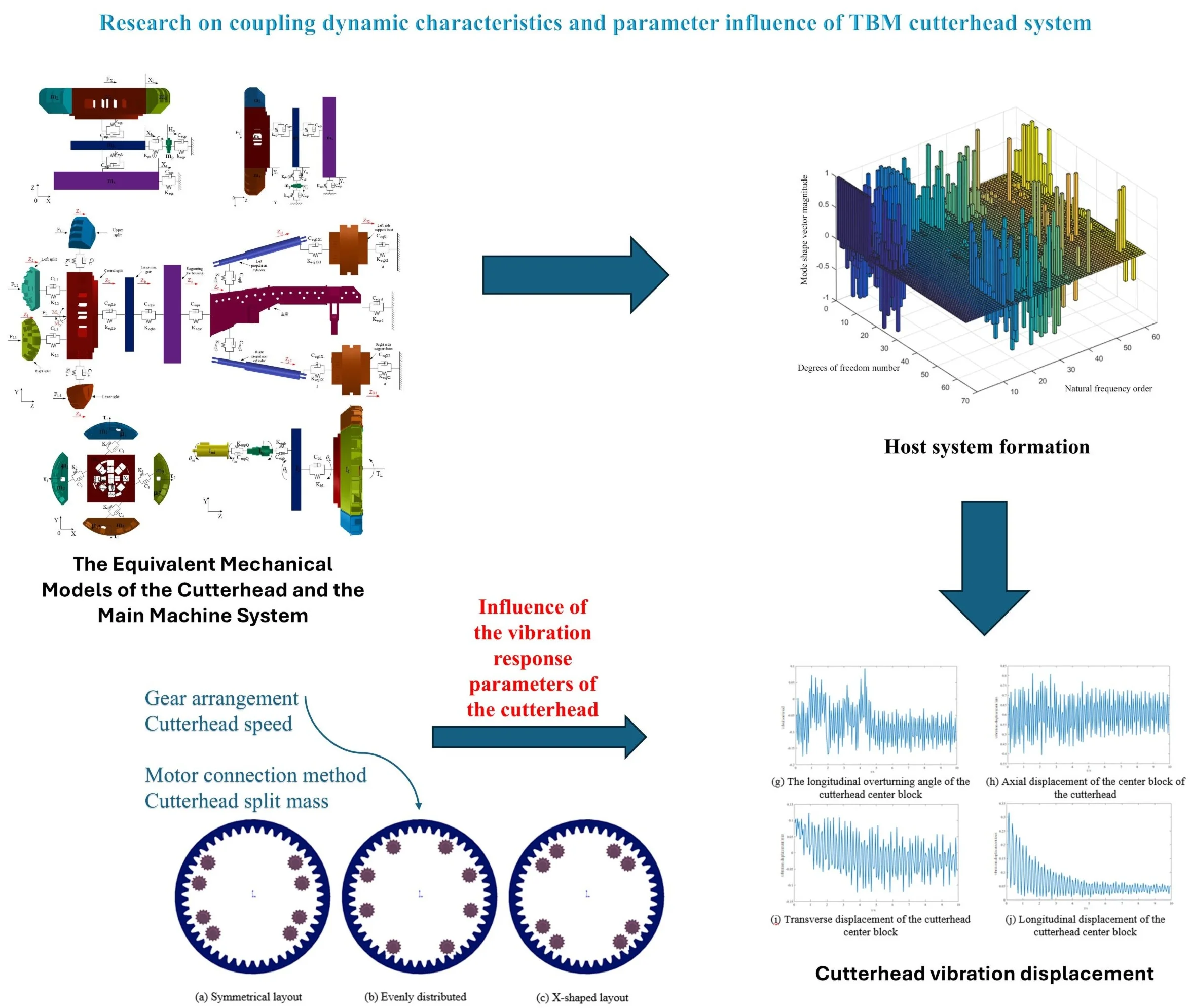
As an important system of TBM, the host system bears the impact of unstable load from itself and the strong load of the rock in the geological layer during operation, which causes irregular vibration of the host system, resulting in low tunneling efficiency, and is more likely to cause cutterhead cracking and component damage. To this end, with the help of analysis software such as Matlab and Ansys, the intrinsic characteristics and vibration response of the host system are studied, and the specific parameters of the vibration influencing factors are discussed. The results show that the axial displacement of the center block of the cutterhead is the largest, reaching 0.85 mm, and the longitudinal displacement value is about 2-3 times of the transverse displacement; in the design stage, the mass of the central block should be controlled in the range of 50 %-55 %, and the rest of the cutterhead should be controlled in the range of 12.5 %-13.5 %; the vibration is the smallest under the uniform layout of the gear, the fluctuation of the solid short shaft connection of the motor is relatively stable, and the maximum vibration value does not exceed 3.5e-2 mm.
Highlights
- A dynamic physical model of the cutterhead host system was constructed, with the mass, stiffness, and damping parameters of each component determined, providing a foundation for subsequent vibration analysis.
- The physical equations were numerically solved using the Newmark method, providing accurate computational results for the vibration response analysis of the cutterhead host system.
- The analysis showed that the axial displacement of the center block of the cutterhead is the largest, reaching 0.85mm, and the longitudinal displacement is 2-3 times larger than the transverse displacement.
1. Introduction
In the field of tunnelling, the TBM is an important type of tunnelling equipment, which is available in two types: shield and open. TBM (Hard Rock TBM) technology combines mechanical, electrical, hydraulic, and information processing technologies to minimize disruption to the surrounding environment and provide high-quality and efficient tunnelling services with a high degree of automation. As one of the key components of TBM, the cutterhead needs to fully consider the actual engineering situation and engineering requirements in the design process, but in the actual production, problems such as porosity and inclusions will inevitably occur. The cutterhead works under the conditions of high strength, high geostress and high temperature, and bears the multi-point time-varying and large random load of TBM equipment, and is prone to fatigue damage under repeated loads. In this case, cracks will occur inside the cutterhead, and even fatigue damage will occur, which will bring great safety risks to the unit. Therefore, it is important to understand the internal performance mechanism of the cutterhead by understanding the types of damage caused by vibration and the causes of vibration. By analyzing the significant parameters and optimizing the parameters, the vibration of the cutterhead can be effectively reduced or eliminated.
Many researchers at home and abroad have studied the dynamic performance of key components of TBM through the combination of theoretical modeling and experimental research. In order to reveal the physical mechanism of the interaction between the disc cutter and the tool holder, Huo [1] et al. constructed a dynamic simulation model of a complex hob-tool holder system with multiple binding surfaces and multi-degree of freedom coupling. The influence of contact pressure and lubrication state on the stability of the system was obtained, and the necessary adjustment and optimization of the model were made through experimental methods. By constructing the mechanical model of the rock cut by the hob, Ma Liang [2], [3] simulated the same rock dynamically, and compared it with the experimental results to obtain the optimal disc cutter width parameter. Ling Jingxiu [4] established the dynamics of the TBM cutterhead system, and predicted the fatigue life based on the vibration response results. Xu Younan [5] et al. took the propulsion device as the research object and established the vibration dynamics model of the propulsion system by combining vibration theory and numerical simulation. Combined with finite element analysis, the maximum error value of the natural frequency is 1.37 Hz. Chen Jie [6] verified the effectiveness of the model by solving the dynamic model of the hydraulic propulsion mechanism and combining it with finite element analysis, and the results showed that with the increase of size, the stiffness of the mechanism first increased and then decreased. Huo Junzhou [7] et al. combined BP neural network and the finite element analysis to simulate the static behavior of TBM cutterhead under various load conditions. At the same time, the average error of the reconstructed strain is controlled within 10 %.
In terms of dynamic modeling, there are many studies on the dynamics modeling of multibody systems. At present, the dynamic modeling methods are widely used in the concentrated mass method and the finite element method. Zhang Z. [8] et al. analyzed the specific path of load transfer, compared the vibration response predicted by the theoretical model with the vibration observed during the actual operation. Uncover the difference between theoretical and actual vibration data and provide reliability for optimizing drivetrain performance. According to the complex relationship between the elements of the gear system, Chang L. [9] et al. constructed a model of the continuous gear system, and derived the dynamic equation to reflect its interaction and dynamic characteristics. Chen S. [10] et al. used advanced finite element analysis techniques. Through numerical calculations, the equations of motion of the system affected by the bearing and gyroscopic effects are derived. H Sun [11] calculates the dynamic response of the cutterhead by establishing a dynamic cutting model based on the expansion model and the discrete element method. By studying the crushing stress changes of the disc cutting machine under different rocks, Ling Jingxiu [12] et al. used ANSYS finite element software to analyze the vibration characteristics of the TBM cutterhead under the maximum thrust condition, analyzed the influence of different structural parameters on the vibration of the cutterhead, and optimized the parameters to achieve the effect of vibration reduction In order to explore the dynamic characteristics of the TBM host, Lin L. [13] took an engineering example as the research object to analyze the dynamic response characteristics of the TBM host. Ling Jingxiu [14] based on the established vibration model of a TBM split-cutterhead system, the modal method is used in the dynamic model. The results show that, the 10th-20th order natural frequencies are mainly affected by the cutterhead support stiffness and mass parameters, and the 9th-11th order frequencies are mainly influenced by cutterhead moment of inertia. Wei Sun [15] et al. proposes a method for analyzing the characteristics of different modes is proposed, and a pure rotational dynamic model of multi-stage planetary gear system is established based on the concentrated mass method. The results show that the variation of the individual gear parameters of the system mainly affects the natural frequency of the gear of the same level.
In summary, some progress has been made in the research of multibody dynamics modeling, especially in the field of TBM, and a series of advanced models and theories have been developed to analyze and predict the motion behavior of these mechanical devices under complex geological conditions. At present, the research mainly focuses on the dynamic modeling and analysis of the cutterhead system, and rarely considers the dynamic characteristics of the TBM cutterhead and the vibration of the rear key parts. Therefore, it is necessary to analyze the dynamic characteristics of the cutterhead system from a dynamic point of view.
2. Construction of vibration model and parameter determination of TBM host system
2.1. Host system dynamics established
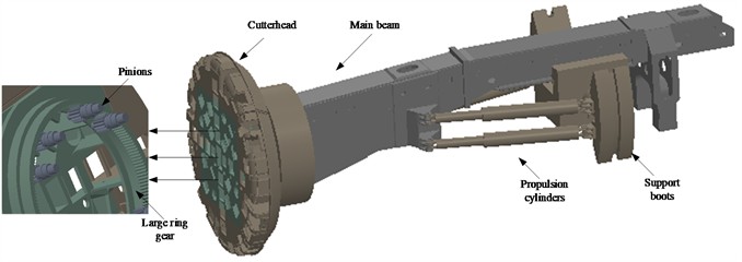
The TBM host system is its core component, covering two parts: the cutterhead system and the support propulsion system. The cutterhead is the main cutting component that cuts and crushes the rock. The support propulsion system provides the necessary stability and maneuverability for the entire TBM. The main beam supports the entire system and regulates the propulsion force by hydraulic control of the propulsion cylinders. Together, these structures enable the TBM to drive stably in complex and variable geological conditions. In the actual operation process, the cutterhead rotation drives the disc cutter to cut and break the rock, which is often accompanied by vibration, and when the vibration is too large, it will cause problems such as cutterhead damage. Therefore, it is particularly important to conduct in-depth analysis and optimization of the dynamic characteristics of the host. Fig. 1 shows the main components of the main unit.
Fig. 1Composition of cutterhead and host system
According to the operation mechanism and component composition of TBM, the axial degrees of freedom involved in the propulsion system are analyzed, and the radial and torsional degrees of freedom in the drive system are considered. For the dynamic modeling of the gear system, it is necessary to pay attention to the installation error between the gears and the dynamic meshing force affecting the gears, so as to ensure the accuracy and reliability of the model. In addition, when modeling the support propulsion system, it is necessary to pay attention to the dynamic support stiffness of the propulsion cylinder. The kinetic model of the TBM host is shown in Figs. 2-6.
Fig. 2Radial equivalence mechanics model of the host system
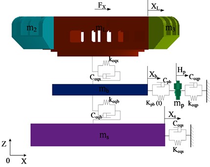
a) Horizontal isometric mechanics model of the host system
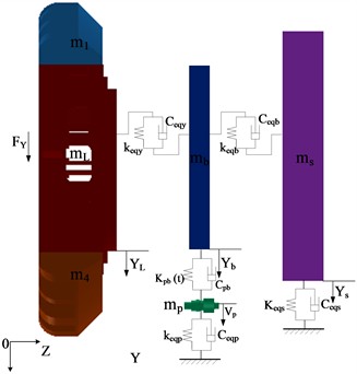
b) Longitudinal isodynamic model of the host system
Fig. 3Torsional dynamics model of the host system
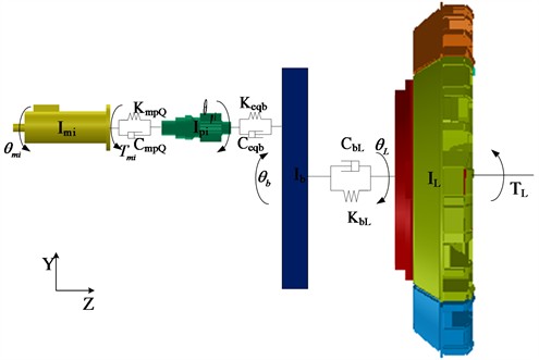
Fig. 4Split dynamics model of cutterhead
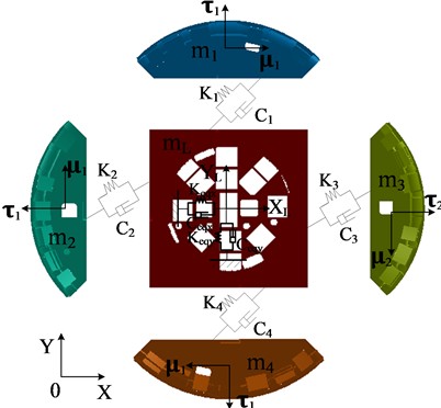
Fig. 5Axial and overturning dynamics model of the host system
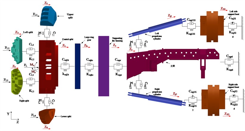
Fig. 6Isometric model of the host rotation system
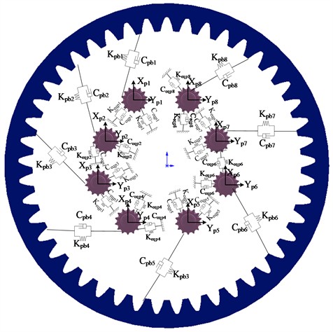
From the perspective of the cutterhead as a whole, the torque fluctuation generated by the rolling force causes the cutterhead to twist and vibrate randomly around the axial direction, and the overturning moment generated by the vertical force causes the cutterbox to bend horizontally and longitudinally. Due to the different number of disc cutters and the structural form of the cutter head, each branch will vibrate in three translation directions, and be coupled with the vibration of the central block. Radial vibration, axial vibration, torsional vibration and bending vibration occur in the center block of the cutter head and the large gear ring under the action of external load, radial vibration and torsional vibration occur in the pinion, and the four edge splits and the support shield of the cutterhead consider the radial and axial vibration. The equivalent dynamic model of the bending-torsional shaft pendulum vibration model with multi-degree-of-freedom coupling of cutterhead-large gear ring-support shield and gear is shown in the above figures, and the physical quantities in the model are described as follows:
, are the relative coordinate system where the cutterhead split is located, which represents the normal and tangential directions of the cutterhead split, respectively; are the pinion coordinate system, which represents the tangential and radial direction of the pinion, respectively.
Among them, represent the mass of the upper split, the left split, the right split, the lower split and the center block on the cutterhead, respectively.
represent the quality of the large gear ring, the support shell, the main beam, the left propulsion cylinder, the right propulsion cylinder, the left support shoe, the right support shoe, and each pinion.
represent the moment of inertia of the cutterhead, the large ring gear, the cutter coil around the , the -axis, the large gear ring around the , -axis, each pinion, and each drive motor around the central axis.
represent the equivalent load torque of the cutterhead, the input torque of each drive motor, the transverse and longitudinal unbalanced force of the center block of the cutterhead, the total axial thrust and the overturning moment of the cutterhead, respectively.
represent the normal, tangential and axial equivalent support stiffness of each split cutterhead, respectively.
represent the axial connection stiffness of the cutterhead center block and the large gear ring, the large gear ring and the support shell, and the support shell and the main beam respectively.
represent the hinged connection stiffness of the main beam and the left propulsion cylinder, the main beam and the right propulsion cylinder, the left propulsion cylinder and the left support shoe, and the right propulsion cylinder and the right support shoe respectively.
represent the axial support stiffness of the left support shoe, the right support shoe and the surrounding rock, respectively.
represent the damping coefficients corresponding to each equivalent stiffness.
According to the equivalent force chemistry model, the generalized displacement matrix of the cutterhead system is:
where is the number of cutterheads, and is the number of small wheels.
In the matrix, represent the tangential displacement, normal displacement and axial displacement of each split cutterhead, respectively; represent the lateral displacement, longitudinal displacement, axial displacement, overturning vibration displacement, and torsional vibration displacement of the cutterhead center block respectively; represent the lateral displacement, longitudinal displacement, axial displacement, overturning vibration displacement and torsional vibration displacement of the large ring gear, respectively. represent the transverse displacement, longitudinal displacement and axial displacement of the support shell, respectively; represent the tangential displacement, radial displacement and torsional vibration displacement of each pinion, respectively; represents the angular displacement of the torsional vibration of each motor.
2.2. The differential equations for the dynamics of the host system are established
According to Newton’s second law and the equilibrium relationship between the spring force, damping force, inertial force and external excitation acting on each component, the differential equation for each component is established as follows.
1) Cutterhead split:
2) Cutterhead center block:
3) Large ring gear:
4) Supporting the housing:
5) Pinions:
6) Motor:
7) Main beam:
8) Propulsion cylinders:
9) Support boots:
2.3. Calculation of kinetic system parameters
The calculation method of the internal excitation of the system is analyzed, and the coefficient matrix of the system of dynamic differential equations is determined. By accurately calculating the coefficient matrix, it is possible to better understand and predict the performance of the host system under various working conditions, so as to optimize the design and improve the production process to ensure the efficient and safe operation of the equipment.
2.3.1. Calculation of the stiffness of the structural part
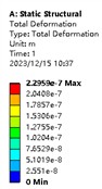
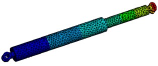
Due to the complexity of components such as cutterheads and shells, there is no mature stiffness solution formula. Therefore, the finite element analysis software ANSYS was used to calculate the stiffness of the cutterhead, main beam, support shoe and other components, and the deformation value was obtained through Hooke’s law , and then the stiffness of the component was solved. The specific process is to constrain one end of the model, and apply a load to the other end to obtain the result contour. Taking the finite element stiffness analysis of the propulsion cylinder as an example, the force of 10000 N is applied to it, and the deformation is 2.3e-7 m, and the stiffness of the cylinder is 4.3e10 N/m by combining the formula, and the analysis results are shown in Fig. 7.
Fig. 7Finite element calculation of propulsion cylinder stiffness
2.3.2. Large ring gear stiffness calculation
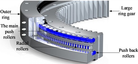
In a cutterhead system, solving the stiffness of the large ring gear is actually equivalent to calculating the stiffness of the main bearing, due to the integrated structure of the ring gear and the main bearing. The main bearing is mainly composed of an outer ring, an inner ring and three rows of cylindrical rollers, as shown in Fig. 8.
Fig. 8Schematic diagram of bearing structure
The TBM main bearing belongs to the radial thrust bearing, and its axial stiffness can be defined as:
where – take 1.11 for roller bearings; – the number of rollers; – bearing contact angle of 90°; – axial displacement of the bearing; – the bearing stiffness coefficient is calculated as follows:
where – effective contact length of rollers; – effective diameter of rollers.
Under the pure axial load , the bearing load displacement can be expressed as:
Radial bearings are mainly subjected to radial loads, and the radial stiffness of the bearings is defined as:
where – take 1.11 for roller bearings; – the number of rollers; – radial displacement of the bearing; – coefficient, which is calculated as follows:
where – he angle of position of the rollers.
Similarly, under a pure axial load , the radial displacement of the bearing can be expressed as:
The stiffness calculation and parameter determination of the above main bearing are obtained from the mechanical design and related literature [16], and it can be seen that the stiffness value is not a constant value, but changes with the axial displacement and load, radial displacement and load, and has time-variability.
2.3.3. Damping parameter calculations
Damping inside the system is an important parameter that plays a key role in the dynamic characteristics and stability of the system. Due to the complexity of the host structure, it is often not possible to complete testing during the design phase. Therefore, in order to solve the testing difficulties, we can rely on some empirical formulas to calculate the damping of the system.
2.3.3.1. Calculation of equivalent damping of structural parts
For components such as cutterheads, the damping is calculated according to the formulas inherent in the mechanical design manual:
where, is the damping ratio, and the steel structure is generally taken from 0.02-0.05 in the elastic stage, and the value in this paper is 0.02; and are the equivalent mass and equivalent stiffness of the structural parts, respectively.
2.3.3.2. Calculation of the equivalent damping of the large ring gear
By searching the relevant literature, it is obtained that the damping of the large ring gear is calculated as follows:
2.3.3.3. Gear meshing equivalent damping calculations
Calculated from previous empirical formulas:
where, is the gear meshing damping ratio, which can generally be taken as 0.03-0.17, and is the average meshing stiffness of the gear pair. and are the masses of active and driven gears, respectively.
2.3.3.4. Torsional equivalent damping calculations
By searching the relevant literature, the empirical formula for torsional equivalent damping is as follows:
where, represents the torsional damping ratio of the shaft, which is 0.005-0.075, and 0.005 in this paper; denotes torsional stiffness.
3. Based on the analysis of the dynamic characteristics of the cutterhead system of the Newmark method
3.1. TBM cutterhead parameters and construction parameters
Before solving the dynamic equation, the system parameters should be input first, including the cutterhead size, mass and some component parameters such as large ring gear and gear, and the main parameters are: cutterhead diameter 8.53 m, rated speed 5.6 r/min, propulsion speed of 3 m/h, and driving power of 3440 kW. The parameters are shown in Table 1 and Table 2.
Table 1Basic parameters of the cutterhead system
System parameters | Cutterhead split | Cutterhead center block | Large ring gear | Support the shield | Pinions |
Quality (kg) | = 1.74e4 | = 5.91e4 | = 846 | = 6.2e4 | = 167 |
Torsional stiffness (N·m/rad) | = 6.06e12 | = 4.09e6 | |||
Translational stiffness (N/m) | = 1e10 | = 1e11 | = 2e10 | = 1e12 | = 2.7e10 |
Axial stiffness (N/m) | = 2.5e10 | = 8e10 | = 3.6e11 | = 1e12 | |
Number of teeth | = 174 | =14 | |||
Modulus (mm) | 22 | ||||
Engagement angle (°) | = 20 | ||||
3.2. The dynamic solution process of cutterhead based on Newmark method
The Newmark method, also known as the direct integration method, is a numerical integration method used to solve structural dynamics equations. According to the recursive relationship of the state vectors at the time of three sets of unknown solvers are solved, which are displacement, velocity, and acceleration. The motion relationship between the velocity and the amount of displacement change is:
Table 2Structural parameters of the propulsion system
System parameters | The front section of the main beam | The middle section of the main beam | The end section of the main beam | Support boots | Propulsion cylinders | Motor |
Quality (kg) | = 2.17e4 | = 2.2e4 | = 2.15e4 | = 2.25e4 | ||
Stiffness (N/m) | = 5e10 | = 5e10 | = 5e10 | = 8e10 | ||
Cylinder support angle (°) | 15 | |||||
Cylinder reaming | ||||||
Motor azimuth (°) | 26, 52, 128, 154, 206, 232, 308, 334 | |||||
This formula is a basic recursive formula, and the basic idea of the Newmark method is to use two parameters to control the acceleration and speed of the approximate solution. These two parameters are called and , respectively, and the accuracy and numerical stability of the solution can be controlled by adjusting their values. When , ,the Newmark method converges unconditionally, and only the solution accuracy of the time step is considered, that is, the acceleration value is a constant of .
The numerical integral equation of the Newmark method can be expressed as:
The equation for the displacement obtained by simultaneous Eq. (3):
where , and represent the mass matrix, damping matrix, and stiffness matrix, respectively. According to Eq. (3), the displacement at time can be solved, and then the velocity and acceleration can be solved. According to the above analysis, the specific calculation process of Newmark method is obtained. Based on the above TBM structural parameters and construction parameters, the Newmark method was used to analyze the cutterhead system, and the dynamic response of the TBM cutterhead system and the main beam and other components was calculated.
3.3. Analysis of the intrinsic characteristics and vibration response of the cutterhead system
The cutterhead system is subjected to forces in different directions during the tunneling process, including propulsion, cutting force, friction force, etc. The dynamics calculation can be carried out by using the system dynamics model established in the previous chapter, and considering the mass, inertial force, inertial coupling and other factors of the system, to evaluate the force and dynamic response of the system. After ignoring the external excitation and internal damping, the linear invariant free equation is obtained:
Assuming that the dynamical system has degrees of freedom, that is, natural frequencies correspond to it, it can also be regarded as the vibration of the nth degree of freedom system, and one of the vibration forms is taken to solve it:
Derivatives are sought continuously:
Eq. (29) and Eq. (30) are substituted into Eq. (28):
The frequency equation can be derived as:
The solution represents the mode shape vector and represents the natural frequency, i.e., the eigenvector and eigenvalue corresponding to the solution. The intrinsic characteristic stiffness matrix of the host system can be obtained, with a total of 64 degrees of freedom, corresponding to 64 natural frequencies and mode shapes, as shown in Table 3, some natural frequencies and mode shapes of some host systems. Table 4 shows the rotation frequency and meshing frequency of the gear and the large gear ring.
Fig. 9Host system formation
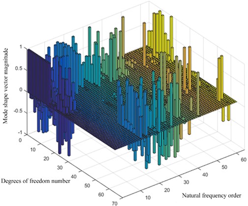
The following three-dimensional histogram 10 is drawn by using the bar3 instruction function: where the degree of freedom is 1-64, corresponding to the degree of freedom of each component in the host.
From the above mode shape vector diagram, it can be seen that the deformation vibration of the host system mainly exists in the intermediate order. The first 19th-order vibration forms are mainly motor and gear torsional vibration and cutterhead translational vibration, and the low-order frequencies of gears and large gear rings occur at 8.8 Hz and 32 Hz, compared with the rotation frequency and meshing frequency in Table 4, the resonance phenomenon is avoided.
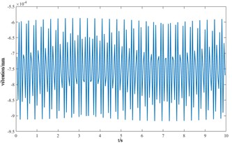
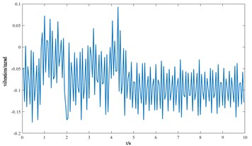
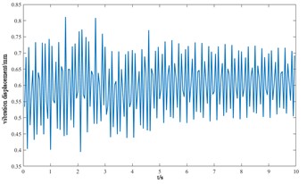
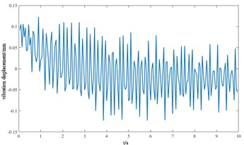
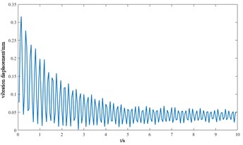
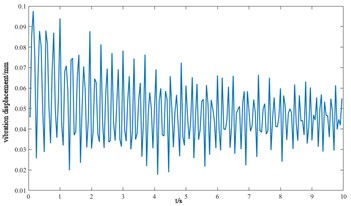
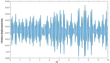
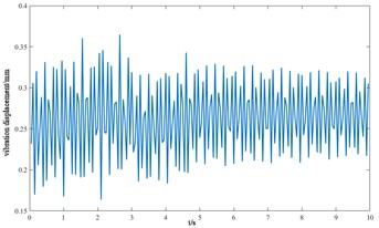
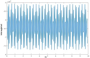
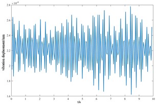
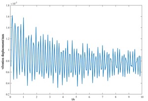
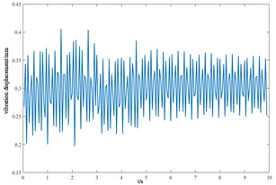
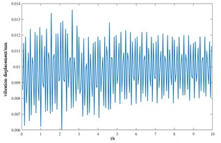
Fig. 10Vibration response of each component of the cutterhead system
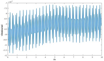
a) Motor torsion angle
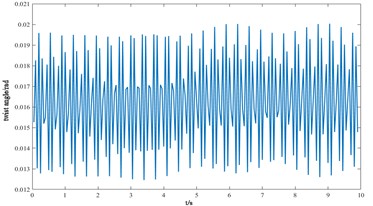
b) Gear to rsion angle
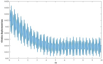
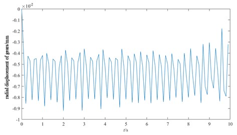
c) Transverse displacement of gears
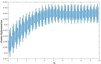
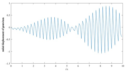
d) Longitudinal displacement of gears
e) The angle of torsion of the center block of the cutterhead
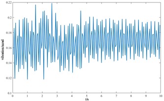
f) The angle of lateral overturning of the cutterhead center block
g) The longitudinal overturning angle of the cutterhead center block
h) Axial displacement of the center block of the cutterhead
i) Transverse displacement of the cutterhead center block
j) Longitudinal displacement of the cutterhead center block
k) Transverse displacement of ring gear
l) Longitudinal displacement of ring gear
m) Axial displacement of ring gear
n) Ring gear torsion angle
o) Lateral displacement of the shield
p) Longitudinal displacement of the shield
q) Axial displacement of the shield
r) Axial displacement of the main beam
Based on the Newmark method, the vibration response curves of each component of the cutterhead system in torsion, overturning, transverse and longitudinal and axial degrees of freedom are shown in Fig. 10, and the positive and negative signs represent the coordinate direction of the cutterhead, not the negative value.
From the vibration response curves of each component of the cutterhead system, it can be seen that: (1) the torsion angle of the motor and the torsion angle of the gear change periodically with the working time of the cutterhead. The transverse displacement vibration of the gear is in the range of 0.01 mm-0.028 mm, and the longitudinal displacement vibration is in the range of 0.012 mm-0.032 mm, and the vibration decreases with time, and then tends to be stable. (2) The horizontal and longitudinal overturning changes of the cutterhead center block are consistent, and the vibration angle is located between 0.1 mm-0.22 mm. In the three-way vibration displacement, the displacement is the largest due to the maximum force in the axial direction, reaching 0.85 mm, and the longitudinal displacement value is about 2-3 times of the transverse displacement. (3) The three-way vibration displacement in the gear ring is the same as that of the cutterhead, and the axial displacement is the largest, which is an order of magnitude higher than that of the transverse and longitudinal direction. Due to the load transmission consumption, the vibration displacement of the shield is smaller than that of the cutterhead and ring gear, the axial displacement is in the range of 0.006 mm-0.014 mm, and the vibration displacement of the main beam is in the range of 0.02 mm-0.045 mm.
Table 3Natural frequencies of cutterhead systems
Vibration mode morphology | Natural frequency (HZ) |
Rigid body mode | = 0 |
Torsional vibration of motors and gears | = 8.8, 32, 36, 46, 48 |
Cutterhead translational vibration | = 8.8, 32, 36 |
Table 4Meshing frequency of gears and ring gears
Component | Number of teeth () | rotate speed (r/min) | Frequency (r/s) | Meshing frequency (Hz) |
Pinions | 14 | 77.8 | 1.3 | 18.2 |
Large ring gear | 174 | 6.26 | 0.1 | 18.2 |
4. Analysis of the influence of the vibration response parameters of the cutterhead
4.1. Cutterhead split mass
During the construction of underground tunnels, the proportion of the mass of the cutterhead split will change the vibration amplitude of the cutterhead, which will have a certain impact on the performance and efficiency of TBM tunneling. The split mass ratio of the cutterhead refers to the ratio between the mass of the cutterhead itself and the total mass of the entire TBM equipment. The cutterhead is the main tool of TBM, and its quality and design have a significant impact on the efficiency and stability of the tunneling.
Assuming that each of the four splits accounts for % of the total weight of the cutterhead and the mass of the four splits is the same, the mass of the center block accounts for (1 – 4) %, and the mass of the split generally accounts for 10 %-15 % of the total mass of the cutterhead from the previous engineering cases, and the actual cutterhead mass proportion parameters shown in Table 5 below analyze the variation law between the amplitude of the split and the center block under the mass proportion of different cutterheads, as shown in Fig. 11.
Fig. 11The relationship between the mass proportion of the cutterhead and the vibration amplitude
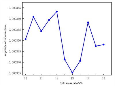
a) The influence of the split quality of the cutterhead on the vibration amplitude of the cutterhead
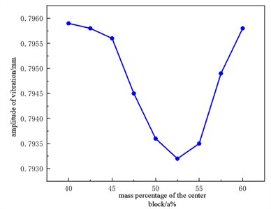
b) The influence of the mass of the center block of the cutterhead on the vibration amplitude of the cutterhead body
Table 5Cutterhead center block and split mass
Mass percentage of the center block | 40 | 45 | 50 | 55 | 60 |
Center block mass (kg) | 25600 | 28800 | 32000 | 35200 | 38400 |
Split mass ratio | 15 | 13.75 | 12.5 | 11.25 | 10 |
Split mass (kg) | 9600 | 8800 | 8000 | 7200 | 6400 |
It can be seen from the figure that the amplitude of the split cutterhead decreases with the increase of the proportion, and when the mass proportion is close to 12 %, the amplitude is the largest, and then the vibration of the cutterhead decreases. When the proportion is 13 %, the amplitude is the smallest, which is also the best advantage of the proportion of the split mass of the cutterhead, and then the amplitude begins to increase, entering a situation of fluctuating up and down. When the mass of the cutterhead center block accounts for 53 %, the amplitude is the lowest. In the design stage, the mass of the central block should be controlled in the range of 50 %-55 %, and the rest of the cutterhead should be controlled in the range of 12.5 %-13.5 %.
4.2. Cutterhead speed
Taking the case of the Northwest Liaoning project as the object, the diameter of the Robbins TBM cutterhead is 8.53 m, and the common cutterhead speed is between 1 rpm-7rpm, and the parameters selected by the engineering excavation experience are: 1.44 rpm, 2.7 rpm, 4 rpm, 5.44 rpm and 6.85 rpm. According to these speed parameters, keeping the rest of the parameters unchanged, the system vibration displacement RMS is solved, that is, the root mean square value of the vibration displacement, which is used to represent the effective values of the velocity, acceleration or displacement of the vibration, reflecting the vibration state and operation of the equipment. The curve variation law between the radial displacement RMS, the torsional angular displacement RMS and the cutterhead speed is obtained as shown in Fig. 12.
Fig. 12The relationship between cutterhead speed and cutterhead vibration displacement (RMS)
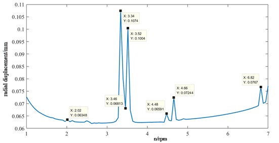
a) Radial vibration displacement (RMS) response
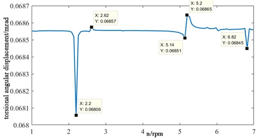
b) Torsional vibration displacement (RMS) response
When the speed is in the range of 1-3 rpm, the cutterhead fluctuates relatively gently in the radial direction, and then there is a large peak fluctuation in the 3-4 rpm range, and then there is a small fluctuation but the overall trend is stable. The torsion of the cutterhead is relatively stable in the range of 1-2 rpm and 3-5 rpm, and the fluctuation of other speeds is obvious, and the root mean square value of displacement is the smallest at 2.2 rpm. Therefore, it is necessary to avoid working at 2.02 rpm, 2.62 rpm, 3.42 rpm, 3.52 rpm, 4.66 rpm, 5.2 rpm, 6.82 rpm, etc., and make appropriate adjustments and optimizations to achieve the best tunnelling results.
4.3. Gear arrangement
Assuming that on the TBM host system, the gear layout mainly includes uniform arrangement, symmetrical arrangement and uneven arrangement, and the specific distribution of the three gear layout modes is shown in Fig. 13, and the vibration response of the cutterhead is analyzed for different layouts as shown in Fig. 14.
In the radial displacement, the vibration displacement of the three gear layouts oscillates up and down, and the overall change law is the same, among which the vibration amplitude of the symmetrical gear layout is the largest, reaching 0.2mm, and in the torsional vibration, the vibration influence of the three gear layouts is smaller than that of the radial vibration. Therefore, in the selection of gear layout, we should try to choose a uniform layout to avoid problems such as gear wear and fracture caused by it, so as to reduce the failure rate and improve the reliability of the equipment.
Fig. 13Gear layout
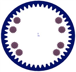
a) Symmetrical layout
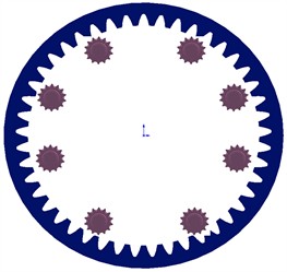
b) Evenly distributed
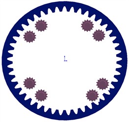
c)-shaped layout
Fig. 14Relationship between gear layout and cutterhead vibration displacement
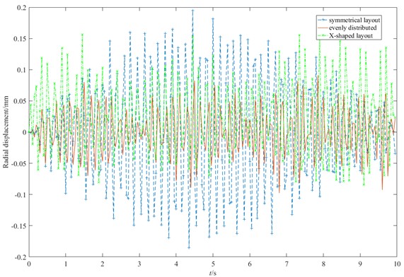
a) Radial vibration
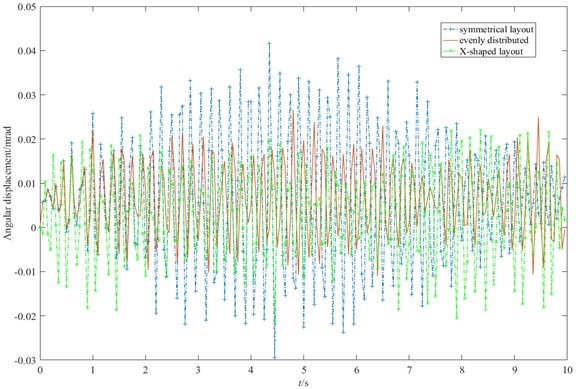
b) Torsional vibration
4.4. Motor connection method
The connection mode of TBM gear of different engineering models is also different, and its main connection mode has three modes: solid short shaft, solid long shaft and hollow long shaft, and the corresponding torsional stiffness of the gear is shown in Table 6, which is written into Matlab respectively according to the parameters in the table for solving, and the vibration response of the gear is shown in Fig. 15.
Fig. 15Relationship between motor connection shaft and gear vibration response
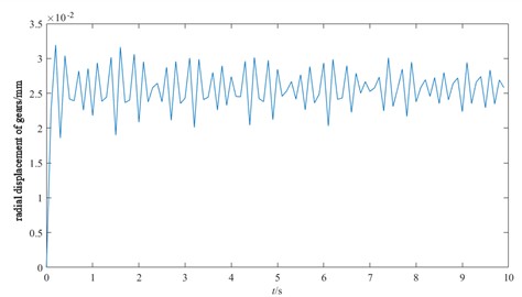
a) Solid short shaft connection
b) Solid long axis connection
c) Hollow long axis connection
Table 6Motor connection parameters
Motor connection method | The length of the motor drive shaft (m) | Corresponds to the torsional stiffness of the gear (N·m/rad) |
Solid stub shaft | 0.5 | = 8.90e7 |
Solid long shaft | 8.5 | = 5.23e6 |
Hollow long shaft | 8.5 | = 4.09e6 |
From the above three types of motor connection shafts and radial vibration, it can be seen that the fluctuation of the solid short shaft connection of the motor is more stable than that of the solid long axis connection of the motor, and the maximum vibration value does not exceed 3.5e-2 mm. However, the fluctuation of the hollow long axis connection of the motor is obvious, and the span between the minimum and maximum values is large. In TBM excavation, the hollow long shaft connection of the motor should be avoided as much as possible to ensure the optimal torsional stiffness parameters of the gear, so as to improve the tunneling efficiency and economy of TBM.
5. Conclusions
By simulating the composite geological conditions, the cutterhead load is calculated, and the multi-degree-of-freedom dynamic model of the host system is constructed according to the centralized mass method, and the dynamic equation is solved based on the Newmark method, and its eigenvalues and eigenvectors are obtained, the natural frequencies and mode shape vectors of the host system are studied, and finally the main factors affecting the vibration response of the cutterhead are analyzed. The following are the main findings of this paper:
1) The deformation vibration of the host system mainly exists in the intermediate order. And the low-order frequencies of gears and rings occur at 8.8 Hz and 32 Hz. In the vibration response of the cutterhead system, the following rules are mainly presented: 1) The torsion angle of the motor and the torsion angle of the gear change periodically. The transverse and longitudinal displacement vibration of the gear is in the range of 0.01 mm-0.032 mm. 2) The horizontal and longitudinal overturning changes of the cutterhead center block are consistent, and the vibration angle is between 0.1 mm-0.22 mm. The axial displacement in the three-way vibration displacement is the largest, reaching 0.85 mm, and 3) the axial displacement in the ring gear is the largest, which is an order of magnitude higher than that in the transverse and longitudinal direction. The axial displacement of the shield is in the range of 0.006 mm-0.014 mm, and the vibration displacement of the main beam is in the range of 0.02 mm-0.045 mm.
2) The influence of the vibration displacement of the cutterhead is analyzed from the factors such as the cutterhead split, the mass proportion of the center block, the speed of the cutterhead, the gear layout parameters and the motor connection mode. The results show that the vibration amplitude of the cutterhead center block decreases with the increase of the mass of the center block, and the weight of the center block accounts for 53 %. When the cutterhead speed is in the range of 3-4 rpm, the radial displacement vibration fluctuates greatly, and the torsional angular displacement vibration is relatively stable in the range of 1-2 rpm and 3-5 rpm of the cutterhead speed.
3) In the gear layout, the vibration amplitude of the uniform layout in the radial and torsional directions is better than that of the other two layouts. Therefore, in the selection of gear layout, we should try to choose a uniform layout. In the motor connection mode, the vibration of the solid short shaft connection of the motor is small compared to the solid long shaft connection of the motor, therefore, in the TBM tunneling, the hollow long shaft connection of the motor should be avoided as much as possible, and the solid long shaft or short shaft connection should be selected.
The research on TBM host system dynamics is a field of broad prospect and significance, in future studies, we plan to conduct field experiments or further data collection where possible with the support of technology development and relevant collaborators to further validate the conclusions of this study.
References
-
J. Huo, N. Hou, W. Sun, L. Wang, and J. Dong, “Analyses of dynamic characteristics and structure optimization of tunnel boring machine cutter system with multi-joint surface,” Nonlinear Dynamics, Vol. 87, No. 1, pp. 237–254, Sep. 2016, https://doi.org/10.1007/s11071-016-3038-0
-
L. Ma, “Analysis of dynamic characteristics of TBM hob rock breaking with different penetration,” (in Chinese), Internal Combustion Engines and Accessories, Vol. 10, pp. 100–102, May 2022.
-
Ma L., “Dynamic analysis of rock breaking of TBM disc cutter with different penetration,” (in Chinese), Modern Manufacturing Technology and Equipment, Vol. 58, No. 3, pp. 92–95, Mar. 2022.
-
J. X. Ling, “Vibration analysis and life prediction of TBM cutterhead under spatially distributed loads,” Dalian University of Technology, Liaoning, Dalian, China, 2015.
-
Y. Xu, Z. Liu, and C. Jie, “Research on dynamic modeling and condensation method of TBM hydraulic propelling cylinder,” (in Chinese), Machine Design and Research, Vol. 37, No. 5, pp. 99–105, Oct. 2021.
-
C. Jie, “Research on dynamic modeling and cohesion method of TBM thrusting mechanism,” East China Jiaotong University, Jiangxi, Nanchang, China, 2021.
-
Huo J., Ge L., and Zhang Z. Et. Al., “Strain reconstruction of TBM cutterhead at key positions based on BP neural network,” (in Chinese), Journal of Northeastern University (Natural Science), Vol. 44, No. 10, pp. 1455–1463, 2023.
-
Z. Zhang, W. Ji, B. Yang, J. Huo, and X. Li, “Dynamic analysis and vibration reduction of mechanical-hydraulic coupled tunnel boring machine (TBM) main drive system,” Proceedings of the Institution of Mechanical Engineers, Part C: Journal of Mechanical Engineering Science, Vol. 236, No. 1, pp. 115–125, Oct. 2021, https://doi.org/10.1177/09544062211029330
-
L. Chang, H. E. Zhaoxia, and L. Geng, “Dynamic modeling of parallel shaft gear transmissions using finite element method,” (in Chinese), Journal of Vibration and Shock, Vol. 35, No. 20, pp. 47–53, Oct. 2016.
-
S. Chen, J. Tang, Y. Li, and Z. Hu, “Rotordynamics analysis of a double-helical gear transmission system,” Meccanica, Vol. 51, No. 1, pp. 251–268, May 2015, https://doi.org/10.1007/s11012-015-0194-0
-
H.-K. Sun and Y. Gao, “Dynamic cutting force model and vibration analysis of the cutterhead in TBM,” Rock Mechanics and Rock Engineering, Vol. 56, No. 11, pp. 7883–7903, Jul. 2023, https://doi.org/10.1007/s00603-023-03470-5
-
J. Ling, M. Wu, X. Cheng, and X. Tong, “Vibration characteristics of hard rock cutterhead under spatial distribution load,” Vibroengineering Procedia, Vol. 41, pp. 66–70, Apr. 2022, https://doi.org/10.21595/vp.2022.22542
-
L. Lin, Y. Xia, Z. Li, C. Wu, Y. Cheng, and Q. Tan, “Dynamic characteristics analysis with multi-directional coupling in a TBM mainframe,” Chinese Journal of Mechanical Engineering, Vol. 32, No. 1, Dec. 2019, https://doi.org/10.1186/s10033-019-0412-0
-
J. Ling, X. Tong, C. Guo, and Z. Li, “Natural frequency sensitivity and influence analysis of TBM cutterhead system,” Journal of Vibroengineering, Vol. 21, No. 6, pp. 1710–1723, Sep. 2019, https://doi.org/10.21595/jve.2019.20427
-
W. Sun, X. Ding, J. Wei, and A. Zhang, “A method for analyzing sensitivity of multi-stage planetary gear coupled modes to modal parameters,” Journal of Vibroengineering, Vol. 17, No. 6, pp. 3133–3146, Sep. 2015.
-
X. Wang and J. Liu, “Mechanical dynamics modeling and simulation,” Southwest Jiaotong University, Sichuan, Chengdu, China, 2021.
About this article

This work was supported by the Natural Science Foundation of Fujian Province (Grant No. 2022J01390), the China Postdoctoral Science Foundation (Grant No. 2020M671956), Fujian Province Foreign Cooperation Industrialization Project (Grant No. 2021I1006) and Fujian Province technology innovation key research and industrialization projects (Grant No. 2023XQ002).
The datasets generated during and/or analyzed during the current study are available from the corresponding author on reasonable request.
Jingxiu Ling: ideas; formulation or evolution of overarching research goals and aims. Jian Zhao: management activities to annotate (produce metadata), scrub data and maintain research data (including software code, where it is necessary for interpreting the data itself) for initial use and later reuse. Shiming Liu: application of statistical, mathematical, computational, or other formal techniques to analyze or synthesize study data. Wenjing Wang: creation and/or presentation of the published work, specifically writing the initial draft (including substantive translation).
The authors declare that they have no conflict of interest.
