Abstract
Due to the inherent nonlinearity of pneumatic systems, achieving accurate control of pneumatic actuators remains a challenging task. This study compares three control strategies-PID control, fuzzy control, and sliding mode control-used to guide the motion of pneumatic actuators driven by on/off solenoid valves. The primary objective is to evaluate and compare the performance of each controller in the context of servo-pneumatic systems, highlighting their respective advantages and disadvantages. On/off solenoid valves, which reduce system costs, are utilized in this study. Since these valves can only process on/off signals, pulse width modulation (PWM) is employed to modulate the input signal, adjusting the duty cycle and performance time of the valves. Initially, the governing equations for the actuator and valves are presented, followed by an introduction to each controller. The pulse width modulation algorithm is then discussed, which regulates the control signal to the valve’s duty cycle and performance time. Finally, simulation results are provided, comparing the controllers and illustrating their strengths and weaknesses.
Highlights
- Development of rehabilitation devices utilizing impedance control techniques.
- Presentation of effective simulation results, showcasing the performance of different control strategies for pneumatic systems.
- Discuss adaptive control methods and their effectiveness in managing pneumatic cylinder servo systems under constraints.
- Recommendations for future research focused on expanding the applications of pneumatic control systems.
1. Introduction
High speed, accuracy, low cost, and cleanliness are essential requirements for mechanical systems that humans interact with. As such, pneumatic systems are often preferred in these fields. However, nonlinear factors, such as friction, the compressibility of air, and delays in servo valves, make controlling these systems difficult, and there remains a need for more accurate control. Several approaches to designing optimal controllers for pneumatic systems have been proposed. Varseveld and Bone [1] designed a discrete PID controller using a model obtained from system identification methods for position control of a two-way servo-pneumatic actuator. They tested the designed controller with different inputs, but the results were not sufficiently accurate due to: 1) the lack of accuracy in the model and 2) the use of a PID controller. In this study, on/off solenoid valves are used. One method for switching control signals to control the valves is pulse-width modulation (PWM), similar to the approach used by Ahn and Yokota [2], who controlled the position of a pneumatic actuator using on/off solenoid valves and a switch-based intelligent controller. In this and other related works, inaccuracies in modeling and sometimes overlooked parts of the model reduce the accuracy in following the optimal path. Additionally, the controllers introduced in these studies often fail to provide optimal performance and sufficient accuracy. Given the challenges in accurately modeling pneumatic systems, which require more precision in modeling and certainty in system parameters [3], it seems logical to turn to robust control methods and controllers that are not based on models. Therefore, this study compares fuzzy and sliding mode controllers. Sliding mode control is a variable structure control method, a nonlinear technique that controls the system's nonlinear dynamics through high-frequency switching control signals. Since this method involves switching between two different states [3], it is robust against changes in system parameters [4]. In 1994, Paul and Mishra used order reduction techniques to control the position of a pneumatic actuator with a sliding mode controller [5]. Drakunov et al. also applied sliding mode control to overcome Coulomb friction in a pneumatic actuator without a beam [6]. Previous studies in this field have used expensive proportional valves to control the actuator. Professor Zadeh introduced fuzzy logic, which led to the development of fuzzy controllers for nonlinear systems with uncertainties. Chen et al. were among the first to apply fuzzy control for position control of a pneumatic actuator [7], using servo valves in their system. In 2007, Ying controlled a pneumatic robot manipulator using a fuzzy controller and on/off solenoid valves [8], with control signals generated by force feedback. Schulte and Hahn controlled a servo-pneumatic system using state-variable feedback and tabulated fuzzy gains [9]. Investigation on determination of non-linear fundamental frequency of a cantilever beam utilizing non-linear stiffness [10]. analyzing the large amplitude free vibrations of a spring-hinged uniform beam, extending previous work on cantilever beams with tip loads. It incorporates non-linear static analysis and compares results to prior studies. A polynomial function is derived to determine the first-mode natural frequency, accounting for boundary conditions and non-linearity [11]. focusing on the structural design and testing of pouch cells for aerospace and automotive applications. Pouch cells, with high energy density, are made by heat-sealing aluminum-polymer laminates. Tests including lap shear, T-peel, and tensile are conducted to assess laminate properties, while finite element analysis determines pressure capacity under abuse conditions [12]. Studying in large amplitude free vibrations of prismatic and non-prismatic tapered cantilever beams subjected to concentrated tip loads. Using finite element methods, a simple polynomial approach is developed to estimate the first mode frequency. Results show that the frequency increases with tip slope, and tapered beams exhibit higher frequencies than prismatic beams [13]. The suggested anti-windup barrier neuroadaptive control method efficiently addresses trajectory tracking issues in pneumatic cylinder servo systems by employing time-varying barrier Lyapunov functions, an enhanced anti-wind strategy, and an adaptive ELM neural network [14]. This study examines controller efficacy in electro-pneumatic systems by comparing linear and nonlinear models, focusing on their effectiveness regarding energy consumption and control efforts [15]. Introduced an optimal control strategy employing Adaptive Domain Prescribed Performance Control (AD-PPC) in conjunction with PID, optimized through the Evolutionary Mating Algorithm (EMA) for a pneumatic servo system, targeting expedited transient control and stable rod-piston positioning with reduced friction [16]. The research presented a novel switching control technique for a pneumatic X-Y table, resulting in a 50 % increase in response speed and a decrease in control effort. Simulation experiments demonstrate that AISA surpasses PD control, meeting system parameters such as inaccuracy, stability, and power consumption [17]. The research modeled the transient stability of an automated pressure regulator in a clinical ventilator, improving system stability and nonlinearity via PID control architecture, alternate acceleration feedback, and integral control techniques. The system is enhanced for transferrable knowledge and competences with FluidSIM [18]. Industrial automation technology employed rapid-switching solenoid valves in pneumatic position servo control systems. Nonetheless, these valves exhibit nonlinear behaviour, necessitating an appropriate control approach. A novel nonlinear model and Fuzzy-PID switching control approach were introduced, enhancing performance and advancing precise pneumatic motion control [19]. In the present study, pulse-width modulation algorithms and differential equations of a single-acting, two-way actuator with solenoid valves are used to model pneumatic circuits. A PID controller was first designed to track the optimal position. Based on this, fuzzy and sliding mode controllers were then developed and implemented in a closed-loop control circuit. To improve the performance of the controllers, their design parameters were optimized using a genetic algorithm (GA). In other words, in this model, the gain of the sliding mode controller is defined by fuzzy logic using membership functions. Subsequently, the GA is used to find the optimal gain to ensure a robust controller. Finally, the advantages and disadvantages of each controller are highlighted by presenting the simulation results and comparing the controllers.
2. Pneumatic system modeling
The experimental setup consists of various components as follows:
1) Pneumatic cylinder.
2) Position sensor.
3) Pressure sensors.
4) Solenoid valves.
5) Flow control valves.
6) Data acquisition card.
7) Voltage converters.
8) Pressure supply source.
9) Humidity and lubrication system.
10) Computer for processing.
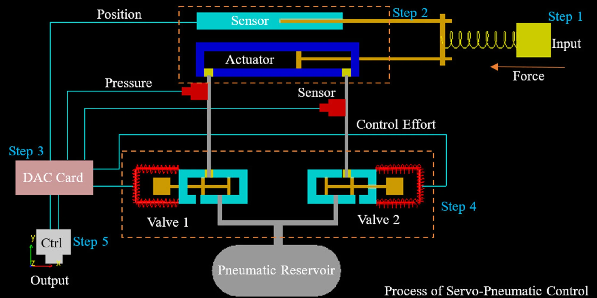
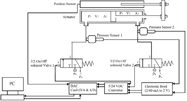
The piston of the cylinder is connected to the position sensor via a coupling and mounted on the laboratory test board. The air from the pressure supply source passes through a filtration system before entering the solenoid valves, and ultimately flows through the flow control valves to the pneumatic cylinder. To measure the input pressure to the cylinder chambers, pressure gauges are placed after the flow control valves in the airflow path. The data acquisition card serves as the communication bridge between the computer and the electromechanical system. The output voltage from the pressure and position sensors serves as input to this card, while the control command is output. The voltage converters are responsible for converting the power supply voltage for the sensors and the data acquisition card. The specifications of each component are presented below. The pneumatic system in this study consists of a pneumatic actuator and two on/off solenoid valves. The pneumatic actuator is a two-way type, and the valves are 3/2 solenoid valves. Apart from the pneumatic components, the system uses pulse-width modulation (PWM) to switch the input control signal to the valves' duty cycle and performance time. The system diagram is shown in Fig. 1.
Fig. 1The schematic diagram of the pneumatic system
The dynamic equations of the actuators and valves are first used to control the system. The equations of motion for the actuator piston are derived in relation to the pressure difference across the two-way cylinder, as well as the effects of Coulomb and viscous friction, including adhesion. The working fluid in the actuator, which is air, is considered an ideal gas. Thermodynamic processes within the cylinder are assumed to be adiabatic, due to the high speed of the processes and the negligible energy exchange with the environment.
Fig. 2the experimental set-up, 1) moisture removing and lubrication system, 2) DC converter, 3) DAQ, 4) voltage converter, 5) DAQ, 6) solenoid valve, 7) pneumatic cylinder, 8) position sensor, 9) presser sensor, 10) flow control valve, 11) external load
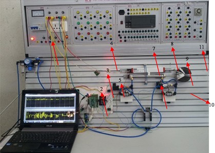
Fig. 3Free body diagram of cylinder piston
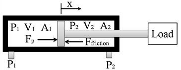
As shown in Fig. 3, the dynamics of the pneumatic actuator are described by the following Eqs. (1-4) [20]:
Two on/off solenoid valves were used to control the actuator based on the equations. Compressed air flows into the actuator chambers from the compressor by applying on/off pulses to these valves. The mass flow rate through the open valves is calculated using the following equation [21]:
where Pu is the upstream pressure, Cd is the discharge coefficient of the valve, Av is the orifice cross-sectional area of the valve at a given moment, T0 is the stagnation temperature, and r is the downstream-to-upstream pressure ratio:
The value of 𝑏 depends on the specific heat of the fluid and can be calculated using Eq. (7) as follows [17]:
The orifice cross-sectional area of the valves depends on their opening and closing speeds. When the valve is opening [19]:
And when the valve is closing:
where, trise and tfall are the required times for opening and closing the valve, respectively.
3. Pulse width modulation algorithm
To control the solenoid valves, the input control signal must be switched to the valves’ duty cycle and time performance. Therefore, a pulse width modulation (PWM) algorithm is used. Since servo applications require the continuous transfer of varying mass flow rates from the valves to the actuators, servo or proportional valves are typically used. However, to reduce system costs, solenoid valves that operate only at maximum and zero flow rates can be utilized. By opening and closing the valves at high frequency using the PWM algorithm, it is possible to transfer the appropriate flow rate from the valves to the actuator. In this algorithm, the control signal u is sampled, and based on its value, the duty cycle of the valves is calculated and transmitted as open/close pulses. Various methods can be used to convert the input control signal into the duty cycle ([2], [22-24]). In this study, the input signal is compared to a sawtooth waveform with a frequency equal to the frequency of the modeled valves.
Fig. 4Schematic diagram of P
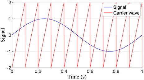
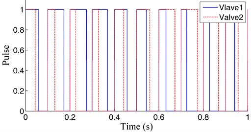
The PWM algorithm calculates the duty cycle and performance time by comparing the input and carrier signals, and generates pulses as shown in Fig. 5.
Fig. 5Generates pulses
4. PID controller design
A classic PID controller is first designed to compare the proposed controllers for tracking the optimal position of the system. The proportional (Kp), integral (Ki), and derivative (Kd) gains are determined using the trial-and-error method. The controller is then optimized by treating these coefficients as design parameters and system error as the objective function. The optimized values of the coefficients are presented in Table 1.
Table 1Optimum gain controller
Input gain opt. | Input gain opt. | Input gain opt. |
Sinusoidal | Kp | 65.48 |
Ki | 1.097 | |
Kd | .317 | |
Step | Kp | 68.167 |
Ki | 3.075 | |
Kd | 1.27 |
4.1. Sliding mode controller design
Due to the nonlinearity of the system equations, nonlinear controllers, such as the sliding mode controller, can be an appropriate choice. Considering force as the control input, and position and velocity as state variables, the system equations are as follows:
˙v=f(X)+b(X)u,
where, f=(-Ffric-Fload)/m and b=1/m. The control rule per second determines the u value. To determine u, the sliding surface is first defined as follows [25]:
where ˜x=x–xd, with xd representing the optimal position, and λ is a fixed, positive parameter associated with the convergence rate. From Filippov’s construction and s=0, the equivalent control of the system is obtained as shown in Eq. (12) [25]:
Finally, to satisfy the sliding constraint, the control signal is given by Eq. (13), with the addition of a discontinuous term based on changes in the sign of s [25]:
In Eq. (13), KSM serves as the control gain and must be chosen to ensure system stability outside the surface. To achieve this, consider s2 as a Lyapunov function:
To establish Eq. (14), KSM must be positive. To eliminate high-frequency fluctuations near the sliding surface, the resulting control rule is modified as follows:
where, φ is the thickness of the boundary layer.
4.2. Fuzzy controller design
Since the servo-pneumatic actuator is used for rehabilitation purposes and the fuzzy controller logic is derived from expert knowledge, this controller can simulate the capabilities of a chiropractor. Additionally, fuzzy controllers are robust and insensitive to uncertainties. The optimization process can be expressed by Eq. (16), considering position error and Gaussian membership functions. The gradient and center of the Gaussian function are treated as design variables:
The fuzzy inference engine uses the tracking signal error and its first derivative as inputs, with control calculated based on Mamdani’s method. The designed fuzzy controller allocates seven membership functions to the error signal, three membership functions to the first derivative of the error, and 21 control rules that govern decision-making based on the control, with seven membership functions. Figs. 6-8 show the membership functions for the inputs and the controller output.
Table 2 shows fuzzy rules used in the controller.
Fig. 9 shows the control surfaces.
Fig. 6Membership function to e
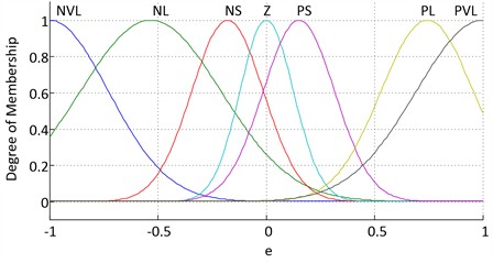
Fig. 7Membership function to de
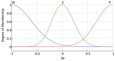
Fig. 8Membership function to u
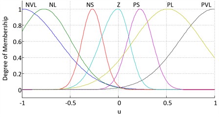
Fig. 9Control surface
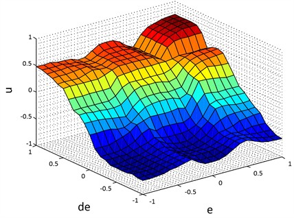
Table 2Fuzzy rules
Fuzzy rules | de | |||
N | Z | P | ||
e | NVL | NVL | NVL | NL |
NL | NVL | NL | NS | |
NS | NL | NS | Z | |
Z | NS | Z | PS | |
PS | Z | PS | PL | |
PL | PS | PL | PVL | |
PVL | PL | PVL | PVL | |
4.3. Genetic algorithm optimization
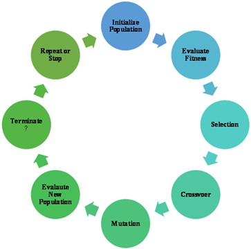
Genetic Algorithm (GA) is an optimization technique inspired by the process of natural selection. It is used to find optimal or near-optimal solutions to complex problems by mimicking the process of evolution based on Fig. 10.
The process involves the following steps:
1) Initialization: A population of possible solutions (often represented as chromosomes or vectors) is randomly generated.
2) Selection: Solutions are evaluated based on a fitness function that measures how well they solve the problem. The best solutions are selected for reproduction, with a higher chance of selection for more fit solutions.
3) Crossover (Recombination): Pairs of selected solutions are combined (crossed over) to create offspring. This process mimics biological reproduction, where parts of the two “parent” solutions are exchanged to create new solutions.
4) Mutation: Random changes are made to the offspring, introducing diversity into the population. Mutation helps prevent the algorithm from converging too early on suboptimal solutions.
5) Evaluation: The fitness of the new offspring is evaluated, and they are added to the population.
6) Termination: The algorithm repeats the selection, crossover, mutation, and evaluation steps until a stopping criterion is met, such as reaching a maximum number of generations or achieving an acceptable solution.
Fig. 10Process of GA
5. Simulation and results
The simulations are performed using MATLAB/Simulink in Fig. 11, to investigate the performance of the optimized controllers. In the solution of differential equations, the general solution comprises two primary components: the homogeneous solution and the particular solution. The homogeneous solution typically consists of functions that are independent of initial or boundary conditions and reflects the intrinsic properties of the differential equation. Conversely, the particular solution depends on the specific conditions of the system and represents the influence of external inputs or forces on the system’s response. During the initial stages (short-term), the overall solution often exhibits an exponential or sinusoidal behavior influenced by the particular solution. At this stage, both components (homogeneous and particular solutions) are observable in the graph, and their combined effects shape the system's behavior. As time progresses and the impact of the external inputs (represented by the particular solution) diminishes toward zero, the overall solution increasingly reflects the homogeneous solution. In this phase, the graph transitions to primarily reveal the characteristics of the homogeneous solution. In essence, over time, the graph converges toward the system's natural and stable behavior, dominated by the homogeneous solution. In summary, the general response of differential equations is defined by these two components, whose temporal variations significantly influence the graph’s shape and characteristics.
Fig. 11Schematic of the servo-pneumatic system under position control
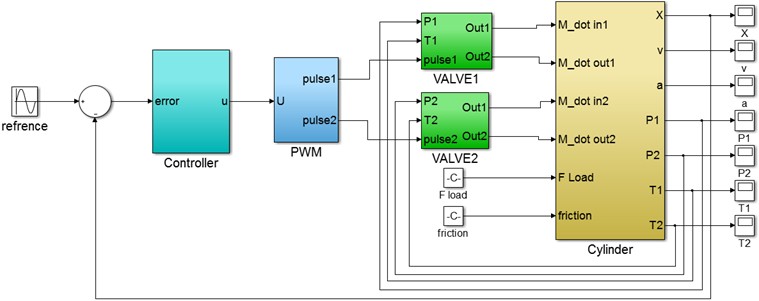
Table 3Properties of system
Property No | Property No |
Piston stroke | 160 mm |
Piston diameter | 16 mm |
Piston rod thread | M10* 1:25 |
Switching time off valve | 2 msec. |
Switching time on valve | 1.7 msec. |
Maximum switching frequency of valve | 330 Hz |
Standard nominal flow rate | 100 l/min |
Compressor pressure | 600 Kpa |
P0 | 100 Kpa |
T0 | 293 K |
The results of the system simulation are presented in Figs. 12-16 for a sinusoidal input with a range of 0.04 m and a frequency of 2π. Initially, the PID signals do not converge due to solving the differential equation Eq. (10), which includes general and particular solutions. Over time, these signals gradually converge.
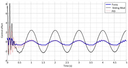
Figs. 12-14 show the ideal sinusoidal path tracking by the actuator for the three controllers. The tracking errors of the three controllers are compared in Fig. 15. The fuzzy controller is more accurate than the others. Fig. 16 compares the output signals of the controllers. As shown in the figure, the sliding mode controller produces a smoother control signal than the other controllers. The results of system simulation for a unit step input with a range of 0.04 m are presented in Figs. 17-21 (with the reference assumed at 0.04 m).
Fig. 12Sinusoidal input for the PID controller
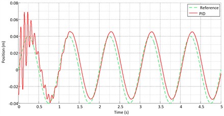
Fig. 13Sinusoidal input for the sliding mode controller
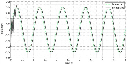
Fig. 14Sinusoidal input for the fuzzy controller
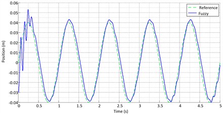
Fig. 15Error for the Sinusoidal input
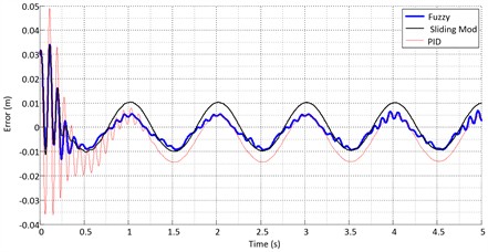
Fig. 16Control effort for the sinusoidal input
Figs. 17-19 show the ideal step path tracking by the actuator for the three controllers. The tracking errors of the controllers are compared in Fig. 20. The results show that the fuzzy controller has higher accuracy than the other two controllers. Fig. 21 compares the output signals of the controllers. As shown in the figures, the sliding mode controller has a smoother control signal than the other controllers. Using the RSSE standard from Eq. (17):
The results show that the fuzzy controller performs better in optimal path tracking than the other controllers. However, when the system position under sliding mode control reaches the sliding surface, path tracking in sliding mode control becomes smoother than in fuzzy control.
Fig. 17Step input for the PID controller
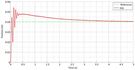
Fig. 18Step input for the sliding mode controller
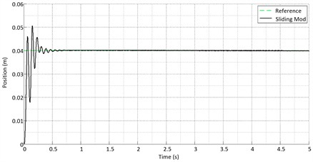
Fig. 19Step input for the fuzzy controller
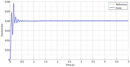
Fig. 20Error for the step input
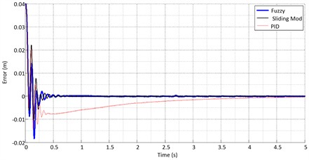
Fig. 21Control effort for the step input
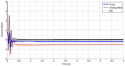
Table 4RSSE Error
Input | Controller | Error |
Sinusoidal | PID | 0.02326 |
Fuzzy | 0.01950 | |
Sliding Mode | 0.01064 | |
Step | PID | 0.01150 |
Fuzzy | 0.00870 | |
Sliding Mode | 0.00608 |
6. Conclusions
This study used two on/off solenoid valves to control the servo-pneumatic position. The PWM algorithm was employed to switch the control signal to the duty cycle of the valves. Additionally, a single-objective genetic algorithm (GA) was used to optimize the control coefficients. The controllers’ performance in tracking two sinusoidal and step inputs was compared. Key factors for controlling a system are response accuracy and control smoothness. A comparison of PID, sliding mode, and fuzzy controllers shows that the fuzzy controller offers high accuracy in path tracking. However, it produces rougher and more fluctuating control signals than the sliding mode controller. In contrast, the sliding mode controller provides smoother control. However, it suffers from fine slides due to a chattering phenomenon, which induces vibration in the system. Adding a boundary layer to the sliding surface would reduce chattering and improve the input control signal, but it may decrease accuracy in path tracking compared to the fuzzy controller. Therefore, due to the uncertainties in the system and the importance of accuracy in position control of the servo-pneumatic system, the fuzzy controller demonstrates more appropriate performance. Based on the conducted investigations, fuzzy logic was chosen for controlling the model. The reasons for selecting this control logic are as follows:
1) The ability of the fuzzy controller to model the knowledge of a physical therapist.
2) The presence of nonlinear structural and parametric factors in the problem.
3) The robustness of the fuzzy controller against disturbances and noise affecting the system.
4) The independence of the fuzzy controller from the system and the simplified system equations.
To control the position and mechanical impedance of the actuator, a PID controller was first designed, and then inspired by it, a fuzzy controller was developed. Subsequently, a single-objective genetic optimization algorithm was used to enhance the performance of the designed controllers. A suitable experimental setup was then designed and constructed to perform the required tests. The controllers were implemented on the experimental system, and their performance in tracking the desired position and mechanical impedance was evaluated. The hardware implementation technique of the setup significantly influenced the results. Experimental charts exhibited disturbances and sudden jumps, which can be attributed to factors such as uneven processing speed of the computer and cylinder jamming due to inadequate lubrication. Based on the results obtained from the simulations, as well as from the experimental implementation and test results, it can be concluded that all the ideas presented for modeling and optimizing the controllers perform effectively, and the controller is able to guide the actuator along the desired path, both in terms of position and mechanical impedance control. Therefore, the results confirm the proper functioning of the control systems. Consequently, since the designed electromechanical setup exhibits sufficient accuracy and performance in both position control and impedance control, it can be used for the development and implementation of rehabilitation devices. The following suggestions are proposed for further research:
1) Mathematical Equation Extraction: Due to factors such as environmental disturbances, viscous-Coulomb friction, and the complexity of the thermodynamic and piston motion processes, extracting precise mathematical equations that describe the system’s behavior is not feasible. Therefore, it is suggested to design a system identification approach based on neural networks that can accurately model the system’s behavior. Furthermore, optimization algorithms could be used to train the neural network to better identify the system’s states and dynamic behavior.
2) Thermodynamic Processes: The thermodynamic processes occurring inside the cylinder chambers differ during the filling and emptying phases. This phenomenon can be treated as an uncertainty. To improve the modeling of this phenomenon, the assumed constant properties of the fluid can be fuzzified, providing a more realistic representation of the working fluid.
3) Artificial Fluidic Muscles: Artificial fluidic muscles are actuators that generate force by contracting and expanding in a diamond-shaped network. There is still limited work in this area, both in terms of modeling and control. It is therefore suggested that future research focus on improving the control of these actuators in rehabilitation systems.
4) Potentiometers as Position Sensors: Potentiometers, used as linear position sensors, have shafts that significantly affect the piston’s dynamics. Additionally, the air transfer hoses and connections introduce friction and time delays that affect the control signal. Therefore, it is recommended to consider modeling these factors in future studies. For example, the use of magnetic sensors could be a suitable alternative to linear potentiometers.
5) Data Acquisition (DAQ) Cards: DAQ cards act as the interface between the controller and the experimental equipment. Cards that process control commands and sensor data serially encounter problems in real-time operations. It is suggested to focus on parallel data processing to avoid any issues that might affect the quality of control algorithm implementation.
6) Impedance Control: In the area of mechanical impedance control, which is critical for interaction with rehabilitation devices, it is recommended to use adaptive controllers that can adjust to varying conditions over time and environmental changes.
References
-
R. B. van Varseveld and G. M. Bone, “Accurate position control of a pneumatic actuator using on/off solenoid valves,” IEEE/ASME Transactions on Mechatronics, Vol. 2, No. 3, pp. 195–204, Jan. 1997, https://doi.org/10.1109/3516.622972
-
K. Ahn and S. Yokota, “Intelligent switching control of pneumatic actuator using on/off solenoid valves,” Mechatronics, Vol. 15, No. 6, pp. 683–702, Jul. 2005, https://doi.org/10.1016/j.mechatronics.2005.01.001
-
M. Bensaada and A. Boudghene Stambouli, “A practical design sliding mode controller for DC-DC converter based on control parameters optimization using assigned poles associate to genetic algorithm,” International Journal of Electrical Power and Energy Systems, Vol. 53, pp. 761–773, Dec. 2013, https://doi.org/10.1016/j.ijepes.2013.05.043
-
V. Utkin, “Variable structure systems with sliding modes,” IEEE Transactions on Automatic Control, Vol. 22, No. 2, pp. 212–222, Apr. 1977, https://doi.org/10.1109/tac.1977.1101446
-
A. K. Paul, J. E. Mishra, and M. G. Radke, “Reduced order sliding mode control for pneumatic actuator,” IEEE Transactions on Control Systems Technology, Vol. 2, No. 3, pp. 271–276, Jan. 1994, https://doi.org/10.1109/87.317984
-
S. Drakunov, G. D. Hanchin, W. C. Su, and Özgüner, “Nonlinear control of a rodless pneumatic servoactuator, or sliding modes versus coulomb friction,” Automatica, Vol. 33, No. 7, pp. 1401–1408, Jul. 1997, https://doi.org/10.1016/s0005-1098(97)00015-0
-
C.-L. Chen, P.-C. Chen, and C.O.-K. Chen, “A pneumatic model-following control system using a fuzzy adaptive controller,” Automatica, Vol. 29, No. 4, pp. 1101–1105, Jul. 1993, https://doi.org/10.1016/0005-1098(93)90109-7
-
C. Ying, Z. Jia-Fan, Y. Can-Jun, and N. Bin, “Design and hybrid control of the pneumatic force-feedback systems for Arm-Exoskeleton by using on/off valve,” Mechatronics, Vol. 17, No. 6, pp. 325–335, Jul. 2007, https://doi.org/10.1016/j.mechatronics.2007.04.001
-
H. Schulte and H. Hahn, “Fuzzy state feedback gain scheduling control of servo-pneumatic actuators,” Control Engineering Practice, Vol. 12, No. 5, pp. 639–650, May 2004, https://doi.org/10.1016/s0967-0661(03)00148-5
-
C. Pany and G. V. Rao, “Calculation of non-linear fundamental frequency of a cantilever beam using non-linear stiffness,” Journal of Sound and Vibration, Vol. 256, No. 4, pp. 787–790, Sep. 2002, https://doi.org/10.1006/jsvi.2001.4224
-
C. Pany and G. V. Rao, “Large amplitude free vibrations of a uniform spring-hinged beam,” Journal of Sound and Vibration, Vol. 271, No. 3-5, pp. 1163–1169, Apr. 2004, https://doi.org/10.1016/s0022-460x(03)00572-8
-
A. Vamsi et al., “Structural design and testing of pouch cells,” Journal of Energy Systems, Vol. 5, No. 2, pp. 80–91, Jun. 2021, https://doi.org/10.30521/jes.815160
-
C. Pany, “Large amplitude free vibrations analysis of prismatic and non-prismatic different tapered cantilever beams,” Pamukkale University Journal of Engineering Sciences, Vol. 29, No. 4, pp. 370–376, Jan. 2023, https://doi.org/10.5505/pajes.2022.02489
-
Q. Yan and Z. Hu, “Neuroadaptive control for pneumatic cylinder servo systems with input saturation and time-varying constraints,” International Journal of Hydromechatronics, Vol. 7, No. 2, pp. 132–154, Jan. 2024, https://doi.org/10.1504/ijhm.2024.138266
-
A. Tootchi and A. Chaibakhsh, “Model-based and model-free position control of a servo pneumatic system in the presence of uncertainties and disturbances,” Proceedings of the Institution of Mechanical Engineers, Part C: Journal of Mechanical Engineering Science, Oct. 2024, https://doi.org/10.1177/09544062241281558
-
A. Irawan, M. H. Sulaiman, M. S. Ramli, and M. I. P. Azahar, “Pneumatic servo position control optimization using adaptive-domain prescribed performance control with evolutionary mating algorithm,” Results in Control and Optimization, Vol. 15, p. 100434, Jun. 2024, https://doi.org/10.1016/j.rico.2024.100434
-
A. Abdelazem, S. R. Tawfeica, and M. Bassily, “Simulation of an x-y pneumatic position control system using a smart control algorithm,” Journal of Advanced Engineering Trends, Vol. 43, No. 1, pp. 451–457, Jan. 2024, https://doi.org/10.21608/jaet.2022.148317.1216
-
S. O. Amudipe, J. F. Kayode, B. A. Adaramola, O. J. Olatunbosun, and S. A. Afolalu, “Simulation of transient response of PID controller in an automated electro-pneumatic system using a single-acting cylinder in a clinical ventilator,” Heliyon, Vol. 10, No. 7, p. e27799, Apr. 2024, https://doi.org/10.1016/j.heliyon.2024.e27799
-
M. Ryu, “Research on fuzzy-pid switching control of electro-pneumatic servo system based on Matlab-Amesim co-simulation,” SSRN, Jan. 2024, https://doi.org/10.2139/ssrn.4956243
-
E. Richer and Y. Hurmuzlu, “A high performance pneumatic force actuator system: part I-nonlinear mathematical model,” Journal of Dynamic Systems, Measurement, and Control, Vol. 122, No. 3, pp. 416–425, Sep. 2000, https://doi.org/10.1115/1.1286336
-
F. Najafi, M. Fathi, and M. Saadat, “Dynamic modelling of servo pneumatic actuators with cushioning,” The International Journal of Advanced Manufacturing Technology, Vol. 42, No. 7-8, pp. 757–765, Aug. 2008, https://doi.org/10.1007/s00170-008-1635-x
-
M.-C. Shih and M.-A. Ma, “Position control of a pneumatic cylinder using fuzzy PWM control method,” Mechatronics, Vol. 8, No. 3, pp. 241–253, Apr. 1998, https://doi.org/10.1016/s0957-4158(98)00005-1
-
Zeljko Situm, Tihomir Zilie, and M. Essert, “High speed solenoid valves in pneumatic servo applications,” in Mediterranean Conference on Control and Automation, Jun. 2007, https://doi.org/10.1109/med.2007.4433746
-
Xiangrong Shen, Jianlong Zhang, E. J. Barth, and M. Goldfarb, “Nonlinear averaging applied to the control of pulse width modulated (PWM) pneumatic systems,” Proceedings of the 2004 American Control Conference, Vol. 5, pp. 4444–4448, Jan. 2004, https://doi.org/10.23919/acc.2004.1384009
-
J. Liu and X. Wang, Advanced Sliding Mode Control for Mechanical Systems. Berlin, Heidelberg: Springer Berlin Heidelberg, 2011, https://doi.org/10.1007/978-3-642-20907-9
About this article

The authors have not disclosed any funding.
The datasets generated during and/or analyzed during the current study are available from the corresponding author on reasonable request.
The authors declare that they have no conflict of interest.
