Abstract
An augmented adaptive sliding-mode controller is proposed in this paper for a diaphragm-type pneumatic vibration isolation (PVI) system containing nonlinear characteristics and time-varying uncertainties with unknown bounds. To capture and deal with the time-varying uncertainties, a controller design based primarily on the functional approximation (FA) technique complemented with an adaptive fuzzy sliding-mode control (AFSMC) is adopted. The resultant hybrid design is denoted as FA+AFSMC to differentiate itself from other attempting solutions. Lyapunov stability theory is utilized not only to stabilize the closed-loop system but also to formulate updating laws for weighting coefficients of the FA and tuning parameters of the AFSMC. This developed scheme has online learning ability when it faces the system’s nonlinear and time-varying behaviors. Experimental explorations which incorporates both pressure and velocity measurements as feedback signals reveals that the proposed FA+AFSMC scheme outperforms other attempting solutions, such as passive isolation and pure AFSMC scheme, by a significant margin.
1. Introduction
Many precision instruments are highly sensitive to ground or environmental induced vibrations. Hence, requirements on the ground vibration level where these instruments are placed have become more important than those specified in standards or regulations [1]. Some research works focusing on vibration control using adaptive or hybrid feedback control can be found in [2-6]. There are numerous practical applications of pneumatic vibration isolator (PVI) in various industries, especially in those cases where PVI operating at low-frequency range of vibration. The reason is that the pneumatic isolation systems are capable of supporting higher payload at relatively lower energy consumption. These PVIs are often actively controlled by servo valves which function to attenuate vibration energy transmitted from the floor and the table itself. This type of PVI-based table system is able to yield satisfactory performances in the frequency range above system’s natural frequencies [7]. However, the performance would deteriorate when the excitation frequency gets closer to system’s natural frequency. To that regard, this paper proposes an active control scheme, i.e. FA+AFSMC, to overcome such a drawback. In other words, by using the proposed control scheme, the vibration isolation performance of the PVI system can be improved over a range of low frequencies, especially at frequencies near system’s resonance.
Due to the compressibility of the air, it has long been known as a challenging task to impose active control on the pneumatic pressure. Shih and Wang [8] applied an adaptive control mechanism to tackle the ground vibration problem. Kato et al. [9] investigated a pneumatic isolation table system using a spool-type servo valve and a pressure differentiator. Although the experimental results demonstrated an efficient isolation performance at lower energy level, this approach requires detailed modeling information of the pressure differentiator as well. More recently, Chang et al. [10] proposed a new state-space model of the PVI using the input-output linearization technique. A time delay controller can subsequently be designed and verified by experiments on a single chamber PVI based on this new model.
Unlike conventional designs which demand elaborated modeling knowledge prior to the implementation, this study employs the functional approximation technique (FAT) to capture nonlinear behaviors of the pneumatic system so that the controller can be implemented. As a result, the requirement of prior modeling knowledge concerning the controlled system can be waived. The FAT has been applied in the past to design adaptive sliding controllers for various nonlinear systems containing time-varying uncertainties [11-13]. In such a design, the FAT approach is integrated with the sliding-mode control (SMC). Here, the FAT is known for its ability in capturing system dynamics while the latter is known for its robustness under conditions of uncertainties and modeling discrepancy. Since the approximation error caused by truncating the infinite series into a finite sum is inevitable in the FAT approach, the SMC can complement such a deficiency to some extent. To further improve the performance of the proposed FAT-based sliding-mode control, an adaptive one-dimensional fuzzy sliding-mode control (AFSMC) [14] compensator with self-tuning capability is also installed in this study. The resultant control scheme is denoted as the FA+AFSMC, namely the FAT-based adaptive fuzzy sliding-mode control. Since the proposed hybrid controller design FA+AFSMC can be deployed in nonlinear systems without modeling information, it can reduce the computational burden and release memory requirement in practical applications. Moreover, the stability of the proposed control scheme can be theoretically ascertained by using the Lyapunov stability theorem.
2. The experimental test rig
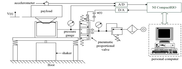
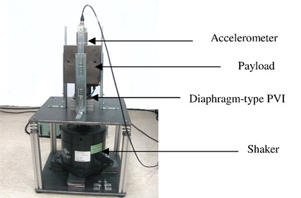
A schematic diagram of the experimental test rig is shown in Fig. 1. The system encompasses the following major components: the PVI sub-system, the accelerometer, the electromagnetic shaker, and the active control unit. Among these, the PVI sub-system is used as an actuator in the active-isolation equipment. It consists of a single pneumatic chamber, a rubber diaphragm, and a piston that supports the payload. A shaker is installed to serve as a vibrating base. For this study, the shaker is used to generate various vibrating profiles for simulating the disturbance variations. In order to measure vibration responses of the isolator, an accelerometer is installed on top of the payload. On the other hand, measurements of both the chamber pressure and payload velocity are incorporated as the feedback signals in the closed-loop control design. In this setup, the payload velocity signal can be obtained by numerically integrating the acceleration signal. The pressure sensor is so located that the pressure measurement directly reveals the pressure dynamics of the air chamber. A PC-based control unit is set to take measurement inputs through A/D conversions. As the brain of the control unit, the control unit computes the required control inputs, and transmits the control input in the form of analog voltage to the pneumatic control valve. The pneumatic control valve, also called servo valve, is a proportional directional control valve which generates air mass-flow in proportion to the control voltage received from the control unit. The spool-type control valve works not only to maintain a static pressure but also to supply the required dynamic pressure for the air chamber.
Fig. 1The schematic diagram of the proposed experimental system
3. Controller design
The control algorithms taken to deal with the nonlinear pneumatic system are elaborated in this section. The fundamental thought behind the proposed scheme is to capture nonlinear time-varying system dynamics by applying the functional approximation technique (FAT). Meanwhile, in order to cope with the finite approximation error, an adaptive fuzzy sliding-mode control (AFSMC), is employed to deal with model discrepancy and uncertainties. The resultant hybrid control scheme is the solution proposed in this paper and is denoted as the FA+AFSMC active isolator. Lyapunov stability theorem is applied to derive update laws for the weighting coefficients and tuning parameters of the FAT and fuzzy control, respectively. Asymptotic stability of the tracking error can be achieved if sufficient number of orthogonal basis functions were adopted. When finite expansion is used, the effects of approximation error on system performance can be investigated. The asymptotic stability can still be ensured with a modified control law if the bounds of approximation error are known.
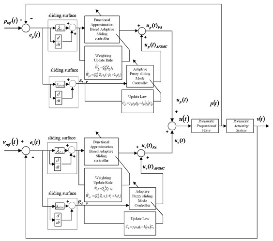
The overall block diagram of the proposed FA+AFSMC control scheme is shown as Fig. 2. Suppose the pneumatic driving system considered here can be represented as the following dynamical equation:
where v(t) represents the payload velocity, fv(v,t) denotes the unknown nonlinear time-varying system dynamics with unknown bounds and bv(t) is an unknown control gain function. The subscript “v” indicates the system properties associated with the velocity feedback control loop. To apply the FAT, two linear combination of Fourier basis functions are employed to approximate the unknown functions fv(v,t) and bv(t). Then the FAT-based sliding controller can be developed for this PVI system. An adaptive fuzzy sliding-mode controller (AFSMC) is added to compensate for the approximation error and improve the control performance. In addition, a Lyapunov function candidate is chosen to not only prove the closed-loop stability but also derive the updating laws for the weighting coefficients of the approximation series and tuning parameters of the AFSMC.
Fig. 2The control block diagram of the FA+AFSMC control scheme
Let ev=v-vr, and consequently, ˙ev=˙v-˙vr in which vr represents the reference velocity of the payload. Next, a sliding variable sv is defined as:
where λv is a positive constant. The time derivative of the sliding variable, sv, is calculated as:
When Eq. (1) is used, Eq. (3) can be recast into the following:
Now in order to satisfy reaching condition of the sliding surface and compensate for the approximation error of the FAT, the control law can be designed to compose of FA and AFSMC two parts. In other words:
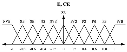
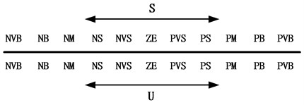
where uvFA indicates the control input calculated in accordance with the FAT, whereas uvAFSMC is the input obtained from the adaptive fuzzy sliding-mode control algorithm. The control uvFA(t) is determined to achieve ˙sv=0 and guarantee the system output error convergence. The estimation terms in uvFA(t) can be approximated by a linear combination of finite orthogonal basis functions to expand and capture most of the time-varying system dynamics plus uncertainties. In addition, ˆfa represents the estimate value of fa=fvˆb-1v while ˆbv is the estimate value of bv. In the proposed hybrid controller, both ˆfa and ˆbv have to be estimated on-line. Note that according to Eq. (5) when ˆbv gets close to zero, the control law becomes unbounded. Therefore, a lower-bound value of bv is required and denoted as b_v. To avoid unbounded control input, the control gain function is designed so that bv≥b_v>0. The membership functions and the fuzzy rules are shown in Fig. 3(a) and 3(b), respectively. Triangular membership functions are used to classify the fuzzy input and output variables. The scaling factor gs is employed to map the sliding surface variable s into the fuzzy universe of discourse. It can be roughly estimated based on the span of tracking error during the experimental investigations. In addition, CTvΦv represents the adaptive fuzzy compensation that can be derived from the fuzzy inference decision and defuzzification operations. CTvΦv can be represented as:
In which Cv=[α1⋯αm]T represents the adjustable consequent parameter vector and Φv=[w1⋯wm]/∑mi=1wi is the firing strength vector. Substituting Eq. (5) into Eq. (4), one obtains:
where, fa, ˆfa, b-1v, and ˆb-1v are assumed to satisfy the Dirichlet conditions. Therefore, they can be represented, by using the functional approximation technique, as:
where Wvf, ˆWvf, Wvb, ˆWvb∈R2n+1 denote the time-invariant weighting vectors used to expand unknown function fa, ˆfa, b-1v and ˆb-1v, respectively, whereas Zf, Zb∈R2n+1 are the time-varying vectors composed of Fourier basis functions. Although, conceptually using sufficiently large number of orthogonal basis functions can approximate the unknown function to a prescribed accuracy, the computation burden increases exponentially as the number of the basis function increases. Moreover, the approximation error still exists. Hence, AFSMC is integrated with the FAT-based sliding control to compensate for the approximation error and the uncertainties. When contents of Eq. (8) is substituted into Eq. (7), the following can be reached:
Here, ˜WTvf=WTvf-ˆWTvf, ˜WTvb=WTvb-ˆWTvb. Moreover, in order to find update laws for ˆWvf, ˆWvb and Cv and to prove stability of the closed-loop system, a Lyapunov-function candidate is selected as the following:
where Qvf, Qvb∈R(2n+1)×(2n+1) are symmetrical positive-definite matrices, whereas γv is a positive constant representing the learning rate of fuzzy controller. Taking time derivative of the Lyapunov-function candidate along the trajectory, one obtains:
Now, since ˙˜WTvf=-˙ˆWTvf, ˙˜WTvb=-˙ˆWTvb and by using Eq. (9), Eq. (11) can be rearranged into the following:
-CTv(svΦv-1γv˙Cv)}.
Next, we select:
where the update law in Eq. (14) is specially designed to make sure that ˆbv will not be less than its lower bound, b_v. Note also that when the appropriate lower bound b_v is chosen, the second and third cases of Eq. (14) will not occur. Parameter γv is a positive learning rate while kv is a positive parameter introducing damping effect to the updating law, Eq. (15) [15]. Eq. (12) can be rewritten as:
where:
Eq. (16) shows that the time derivative of the positive definite Lyapunov function is negative semi-definite. Thus, the dynamics of the closed-loop system is stable in the sense of Lyapunov stability criterion [16]. Furthermore, it can be proven by using Barbarlet’s lemma [17] that the control law uv(t) in Eq. (11) can guarantee asymptotic convergence of the output error.
Note that although the controller design described so far focuses on the velocity feedback loop, similar design procedures can be taken to handle the pressure feedback control loop. Thus, the overall control scheme shown as in Fig. 2 can be obtained.
Fig. 3a) Membership functions of the errors and error changes, b) fuzzy rules of AFSMC
a)
b)
4. Experimental system detail
The experimental setup of the proposed pneumatic vibration isolation system is shown in Fig. 4 in which the PVI sub-system supports a payload. The payload’s mass is 42 kg. The design of the PVI resembles that of a commercial product, namely Bilz Corporation’s FAEBI-HD series. This specialized device has a relatively smaller load volume and a larger damping volume. The total volume of the chamber is about 2.0×10⁻⁴ (m3) while the effective piston area is about 1.96×10⁻³ (m2). An electromagnetic shaker (B&K 4808) driven by a power amplifier is installed to excite the floor base so as to simulate the ground vibration input. The shaker has a force rating of 112 Newton. In order to measure the payload’s, motion a high-quality accelerometer (B&K 8340 with a sensitivity of 9237 mV/g) is installed on top of the payload. In addition, the pressure signal was measured by a high-precision pressure sensor (FESTO SDE1-D6-G2-W18-C-NU-M8 with an accuracy of 2 % of final value) which is mounted in between the exit of the servo valve and the air chamber. To implement control, design the PC-based control unit, consisting of the NI-CompactRIO (NI CRIO-9004) and LabVIEW software, takes measurements through A/D conversions. It then computes the required control signal and transmits the results to the pneumatic control valve. The control valve is a proportional directional control valve (FESTO, MPYE-5-M5-010-B). The valve can generate air mass-flow in proportion to the control voltage. The distance between the control servo valve and pneumatic chamber is kept to a minimum in order to avoid any possible air loss in the pipeline.
During the experimental study, the active isolation control performance is compared against those obtained from the passive isolation configuration. The passive isolation was power free and accomplished by keeping a static pressure in the PVI where the isolation effect was provided by the rubber diaphragm and the orifice flow through the inlet and outlet of the directional control valve.
Fig. 4Photograph of the experimental rig set-up
5. Experimental isolation verifications
In order to demonstrate the enhancement of the isolation performance achieved by using the proposed active-isolation algorithm, tests were run under a pseudo-random ground vibration was fed through the floor. Acceleration responses of the payload were measured and then numerically integrated to obtain the velocity responses. The control results were compared against its counterparts generated by either the passive isolator or the pure AFSMC scheme.
During experimental investigations, the sampling rate was taken as 1,000 Hz. The pressure of air applied to the proportional control valve was 4.3×10⁵ Pa, whereas the static pressure in the chamber was 2.2×10⁵ Pa. The natural frequency of the experimental system as a whole is close to 3.7 Hz. As mentioned previously, a pseudo-random disturbance was applied to validate the proposed control algorithm. This excitation was generated by an electromagnetic shaker. Note that the positive definite matrix Qv is chosen as Qv=QiI in which I represents a 2×2 identity matrix while Qi is a positive constant. In this study, 9 basis functions were adopted in approximating system’s unknown time-varying dynamics. Control parameters used in the FA+AFSMC algorithm are listed in Table 1.
Table 1Values of control parameters.
Controller type | Feedback type | Parameter values |
AFSMC | Pressure | gs=1, gu=0.5, λ=0.1, γ=0.5 |
Velocity | gs=1, gu=15, λ=0.1, γ=0.5 | |
FA+AFSMC | Pressure | Qi=0.01, λFA=0.005, n=9 gs=1, gu=0.2, λAFSMC=0.1, γv=0.5 |
Velocity | Qi=0.01, λFA=120, n=9 gs=1, gu=9.6, λAFSMC=0.1, γv=0.5 |
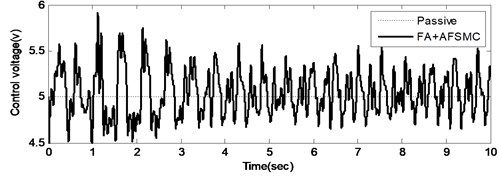
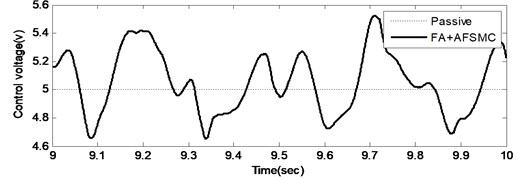
A random-like disturbance was applied to further illustrate the suppression effectiveness of the proposed FA+AFSMC scheme. Time-domain responses including both payload velocity and control voltage input under random-like ground disturbance are given in Figs. 5 and 6, respectively. Note that while Fig. 5(a) and 6(a) show the test data generated across time span of 10 seconds, Fig. 5(b) and 6(b) present the zoom-in details for a single second. It can be observed from these figures that comparing to the passive isolation, the proposed FA+AFSMC scheme can significantly suppress the random-like vibrations of the payload. Since the input signal are randomly generated, only the RMS values of the payload velocity were considered. It turns out that the RMS values of the payload velocity are 0.0087 m/s and 0.0017 m/s for the passive and FA+AFSMC active isolation, respectively. The reduction is about 80 % in this excitation condition.
Fig. 5Time domain payload velocity response (upper: from 0-10 seconds, and lower: with the 9th second) of the passive and FA+AFSMC active isolator under random-like disturbance

a)

b)
Fig. 6Time control voltage (upper: from 0-10 seconds, and lower: with the 9th second) of the passive and FA+AFSMC active isolator under random-like disturbance
a)
b)
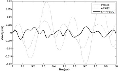
To further illustrate the effectiveness of the proposed control scheme, dynamic responses of the payload velocity for the passive, AFSMC active and FA+AFSMC active control cases are shown in Fig. 7. In this plot, the dashed line indicates the payload velocity of the passive isolator, whereas the dashed-dotted line and solid line correspond to the AFSMC active controller and the proposed FA+AFSMC active controller, respectively. Based on Fig. 7, one can conclude that the proposed FA+AFSMC active controller outperforms either the passive control or the AFSMC scheme.
Fig. 7Time domain payload velocity response of the passive (dashed line), AFSMC active (dashed-dotted line) and FA+AFSMC active (solid-bold line) isolator under random-like disturbance within the 9th second
6. Conclusions
This paper proposes an active control scheme aiming to elevate the isolation performance of pneumatic isolators specifically in the vicinity of the system’s low frequency natural resonance. The approach applies primarily the FAT-based sliding control but is also augmented with the AFSMC compensation (FA+AFSMC) so as to capture and suppress nonlinear and time-varying system dynamics. The AFSMC is adopted for the sake of compensating the finite approximation error caused by truncating the FAT infinite series into a finite sum. Since the proposed approach is modeling-free, tremendous amount of modeling efforts regarding pneumatic isolation system can thus be avoided. The latter is known to be computational challenging because many nonlinear phenomena are involved in such a pneumatic system. Experimental results have shown that the proposed FA+AFSMC active isolation approach can indeed suppress the vibration disturbance effectively. The study also demonstrates the feasibility of designing an active isolation system using both payload velocity and chamber pressure as feedback signal. The future applications of this model-free control methodology will be extended to multi axes isolation systems in our laboratory for further research in this area.
References
-
Gordon C. G. Generic vibration criteria for vibration-sensitive equipment. Proceedings of SPIE, San Jose, CA, 1999.
-
Bitaraf M., Barroso L. R., Hurlebaus S. Adaptive control to mitigate damage impact on structural response. Journal of Intelligent Material Systems and Structures, Vol. 21, Issue 8, 2010, p. 607-619.
-
Li H., Yu J., Hilton C., Liu H. Adaptive sliding-mode control for nonlinear active suspension vehicle systems using T-S fuzzy approach. IEEE Transactions on Industrial Electronics, Vol. 60, Issue 8, 2013, p. 3328-3338.
-
Bitaraf M., Hurlebaus S., Barroso L. R. Active and semi-active adaptive control for undamaged and damaged building structure under seismic load. Computer-Aided Civil and Infrastructure Engineering, Vol. 27, Issue 1, 2012, p. 48-64.
-
Kerber F., Beadle B. M., Hurlebaus S., Stöbener U. Control concepts for an active vibration isolation system. Mechanical Systems and Signal Processing, Vol. 21, Issue 8, 2007, p. 3042-3059.
-
Ozbulut O., Bitaraf M., Hurlebaus S. Adaptive control of base-isolated structure against near-field earthquakes using variable friction dampers. Engineering Structures, Vol. 33, Issue 12, 2011, p. 3143-3154.
-
Shin Y. H., Kim K. J. Performance enhancement of pneumatic vibration isolation tables in low frequency range by time delay control. Journal of Sound and Vibration, Vol. 321, 2009, p. 537-553.
-
Shih M. C., Wang T. Y. Design and adaptive control of a pneumatic vibration isolator. Proceedings of International Conference of Motion and Vibration Control, Vol. 6, Issue 1, 2002, p. 111-116.
-
Kato T., Kawashima K., Sawamoto K., Kagawa T. Active control of a pneumatic isolation table using model following control and a pressure differentiator. Precision Engineering, Vol. 31, 2007, p. 269-275.
-
Chang P. H., Han D. K., Shin Y. H., Kim K. J. Effective suppression of pneumatic vibration isolators by using input-output linearization and time-delay control. Journal of Sound and Vibration, Vol. 329, Issue 10, 2010, p. 1632-1652.
-
Chen P. C., Huang A. C. Adaptive sliding control of non-autonomous active suspension systems with time-varying loading. Journal of Sound and Vibration, Vol. 282, 2005, p. 1119-1135.
-
Huang A. C., Chen Y. C. Adaptive sliding control for single-link flexible-joint robot with mismatched uncertainties. IEEE Transactions on Control System Technology, Vol. 12, Issue 5, 2004, p. 770-775.
-
Spooner J. T., Maggiore M., Ordonez R., Passino K. M. Stable Adaptive Control and Estimation for Nonlinear Systems – Neural and Fuzzy Approximator Techniques. Wiley, New York, 2002.
-
Huang S. J., Chen H. Y. Adaptive sliding controller with self-tuning fuzzy compensation for vehicle suspension control. Mechatronices, Vol. 16, 2006, p. 607-622.
-
Narendra K. S., Annaswamy A. M. A new adaptive law for robust adaptation without persistent excitation. IEEE Transactions on Automatic Control, AC-32, 1987, p. 134-145.
-
Slotine J. J. E., Li W. Applied Nonlinear Control. Prentice-Hall, Englewood Cliffs, New Jersey ,1991.
-
Narendra K. S., Annaswamy A. M. Stable Adaptive Systems. Prentice-Hall, Englewood Cliffs, New Jersey, 1989.
About this article
The authors would like to acknowledge the support of the National Science Council of Taiwan through its Grant NSC-101-2221-E-131-008.

