Abstract
The phenomena of oscillations in sliding mode control system usually cause potential damage or danger in engineering applications. This paper focuses on the estimation and adjustment of oscillation parameters (frequency and amplitude) using an improved describing function method and the characterization of the influence of the reduced-order sliding surface coefficients on the performance of the nonlinear system. The model of series connection of the zero-order holder and switching function is established in frequency domain. The improved describing function method could intuitively estimate the number, stability and parameters of oscillations for the coupled nonlinear system by its amplitude-phase characteristics and pole placement. The stability, parameters and attraction zones of three oscillations in a fourth-order plant are analyzed and simulated. The analytical results show that the reduced-order sliding mode controller possesses complex and colorful nonlinear behaviors. Besides, a coefficient tuning method is presented to eliminate the undesired oscillation which may lead to poor precision or break the stability. The simulations demonstrate that appropriate tuning on sliding surface may greatly improve the efficiency and robustness of the sliding mode control system.
1. Introduction
Sliding mode (SM) control is one of the most common-used robust control algorithms in control system and nonlinear mechanics due to its prominent robust performance [1-3] and low cost [4]. It is also the important nonlinear algorithm in the neural network and machine learning [5, 6]. However, the undesired phenomenon of oscillations in SM system known as “chattering” or “limit cycle” hinders its applications in engineering since the mechanical wear and resonances caused by oscillations. Hence, previous studies [7-9] paid much attention on suppression or elimination of the oscillations in SM controller. Although the high order SM controller, such as the second-order SM [10] and the adaptive PID SM controller [11], would offer oscillation elimination because of the finite-time convergence, the popular high order SM algorithm [12] still exhibits oscillations in the presence of unmodeled dynamics such as parasitic dynamics, delays and hysteresis. Hence, the oscillation-free SM algorithms merely exist in the ideal system without unmodeled dynamic [13]. Hence, it is worthwhile to provide a methodology to assess and adjust the parameters of those hard-to-remove oscillations for practicing control engineers.
Compared with the Lyapunov method and Poincare maps, the describing function (DF) method provides a relatively simple and efficient solution for the oscillation in the nonlinear control algorithm [14, 15]. For the SM algorithm, the DF method and Routh Criterion were employed to predict the stability of oscillations in the uncertain SM system [16]. Its robustness could be tuned by the intersection angle between the Nyquist plot of the plant and the negative reciprocal DF of controller. Besides, the influences of the delay, hysteresis and saturation on the chattering of SM controller were analyzed by the DF method and stability-equation method in frequency domain [17]. In addition, the oscillation in a second-order SM controller could be set by parameter tuning under the guidance of the DF method [12]. The traditional DF method is effective for these uncoupled nonlinearities in [12, 16, 17], which only depends on the amplitude of oscillations. However, the SM algorithm may depend on both the amplitude and frequency of oscillations with the increase of complexity of controllers, and it is hard for the traditional DF method to analyze the coupled nonlinearity in SM controllers.
On the other hand, the sliding surface is closely related to the stability of SM system and oscillation parameters. The most popular full-order sliding surface is a linear combination of all the state variables of the plant [18]. However, it is unpractical to obtain the accurate measurements of high-order state variables in engineering applications. In this case, the output feedback SM controller is a feasible choice, such as the twisting second-order SM [12, 19], when the relative degree is 2 or 3. However, it is challenging for the output feedback SM controller to provide sufficient robustness [20] because of low switching frequency of the signum function when the relative degree is ≥4. Therefore, the reduced-order sliding surface [21, 22] which is the linear combination of partial state variables is a convenient method to decrease the relative degree. Due to the independence of the sliding surface and the high order state variables, the fulfillment of the reachability and stability may become complicated.
Most of the researches assume that the limit cycles in the SM system are always unique and globally stable. Nevertheless, the nonlinear system usually exhibits the local stability. A nonlinear absorber system in [23] demonstrated a complex dynamic of the bi-stable oscillation. The system could approach to the high-frequency oscillation from the low-frequency one after the perturbation of an excitation force. Similarly, the simulation in a PD fuzzy controller [24] illustrated the attraction basin of a limit cycle. When the state portrait started in the attraction basin, it converged to the origin; when the state portrait started out of the attraction basin, it diverged to infinite. A similar phenomenon that two limit cycles existed in a switching power converter was analyzed in [25]. The DF method is an effective tool for analyzing the complex dynamic behavior in the SM system. The existence of multiple limit cycles in a piecewise gain function was proved based on the DF method [26]. The system could switch from a small limit cycle to a large one when a sufficiently large step signal applied to the input. A generalized DF approach was proposed to estimate multiple limit cycles in a SM system [27, 28], and the relation among these limit cycles were revealed intuitively. Under the influence of the sampling interval, multiple limit cycles were found to coexist in a reduced-order SM system [22]. However, the stability of multiple limit cycles in [22, 26-28] was analyzed by using the graphical DF approach which is only fit for the minimum phase system. Hence, the analysis of the stability of limit cycles needs further perfection.
The main contribution of this paper is the prediction of multiple oscillations in the sampling reduced-order SM system by an improved DF method. The characteristic equation of the nonlinear SM system is established and its pole locations are used as the criterion to determine the stability of oscillations. The criterion is valid even the poles located in the right hand s-plane (RHP), hence, the improved DF method is applicable to the minimum and non-minimum phase system. In addition, the parameter tuning method is also introduced to eliminate the undesired oscillation guided by the existence condition of oscillations. In this way, a locally stable system can be tuned as a globally stable one, and the performance of the system can be improved by sufficient gain. The simulations show the existence of three limit cycles which confirms the predictions, and demonstrate the benefit of the parameter tuning method.
The paper is organized as follows. Firstly, the reduced-order sampling SM system is considered. Then the frequency-domain model of the controller is calculated and the improved DF method is derived. In the following section, the complex dynamics including multiple oscillations and their start-oscillation conditions are estimated and simulated. Finally, the coefficient tuning method for eliminating undesired oscillations is presented.
2. Design of the control system
Consider a plant given by the following equation:
where x∈Rn, u∈R1, A∈Rn×n, B∈Rn×1; σ is the SM surface and C∈R1×n is the vector of the sliding surface coefficients, and the control u generated by the SM controller is defined as:
where gain M is a positive constant; k is a sampling counter; Te is a sampling period.
Assume that the high-order state-variables are immeasurable, which means that the coefficients ci corresponding to the immeasurable state-variables equal to zero, then a reduced-order sliding surface could be designed to reduce the complexity of the system. However, the controller may lead to complex dynamic and stability. The following sections will focus on the prediction and adjustment of the multiple oscillations in the reduced-order SM controller.
3. Model of the SM control system in frequency domain
The system can be divided into linear and nonlinear elements. The output of the linear element σ(t) is the input to the nonlinear element, and the output of the nonlinear element u(t) is also the input to the linear element. The linear element is the composition of the plant˙x=Ax+Bu and the sliding surface σ=Cx. Hence, the transfer function of the linear element is W(s)=C(sI-A)-1B, which can also be written as the ration of two polynomials W(s)=P(s)/Q(s).
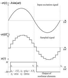
To model the nonlinear element u(t)=f[-σ(t)], its DF should be calculated. Firstly, suppose that a sinusoidal signal -σ(t)=Asin(ωt) (A>0) is applied to the input of M sign [-σ(kTe)], where A and ω denote the amplitude and angular frequency (For simplicity, ω is called the frequency in this paper), respectively. And then, the waveforms of -σ(t) and u(t) are plotted in Fig. 1. The signal -σ(t) is the excitation of M sign [-σ(kTe)] and u(t) is its response. Finally, the nonlinear element f[-σ(t)] can be approximated as a describing function as shown in Eq. (2):
where a1(ω) and b1(ω) are fundamental harmonic Fourier Series which can be obtained by the integral in a period of σ(t):
=1π[ωΔT1∫0[-Mcos(ωt)]d(ωt)+π+ωΔT2∫ωΔT1[Mcos(ωt)]d(ωt)+2π∫π+ωΔT2[-Mcos(ωt)]d(ωt)],
=1π[ωΔT1∫0[-Msin(ωt)]d(ωt)+π+ωΔT2∫ωΔT1[Msin(ωt)]d(ωt)+2π∫π+ωΔT2[-Msin(ωt)]d(ωt)].
According to the waveforms in Fig. 1, u(t) lags behind -σ(t) with uncertain interval ΔT1∈[0,Te] and ΔT2∈[0,Te]. For simplicity, let ΔT1=ΔT2=Te and thus the fundamental harmonic Fourier Series can be written as:
Compared with the uncoupled nonlinearities N(A) which only depends on the amplitude, Eq. (2) is a more complex coupled nonlinearity N(A,ω) which is closely related to the frequency and amplitude. Hence, it is difficult for the traditional DF method to estimate the periodic motion in the coupled nonlinearity. For a simpler analysis procedure, the following section will discuss an improved DF method.
Fig. 1Waveforms of the sinusoidal excitation and response
4. Improved DF method
To estimate the oscillation parameters, the system is presented as a basic feedback structure which consists of the nonlinear element N(A,ω) described by Eq. (2) and the linear element as follows:
Assume that the sliding surface σ(t) moves on the oscillation with frequency ωn and amplitude An; hence, σ(t)=Ansin(ωn)t, and the negative of σ(t) can be written as -σ(t)=Ansin(ωnt-π). After pass through the sampling term and switching function, the signal u(t) is changed in both the magnitude and phase as follows:
where |N(An,ωn)| and θN(ωn) are the magnitude and phase angle of N(An,ωn), respectively.
When u(t) goes through the linear plant W(s), it becomes:
where |W(jωn)| and θW(ωn) are the magnitude and phase angle of W(s), respectively, at the frequency ωn. Substitute:
into Eq. (6a), σ(t) can be rewritten as:
Hence, the amplitude An and frequency ωn can be estimated according the following equations:
However, Eq. (7a) cannot be solved straightforward for a high-order plant. Therefore, the interative operations or function plot can be used to estimate ωn. It proposes that the phase-frequency characteristic φ(ω)=θW(ω)-ωTe can be plotted in the frequency 0≤ω≤π/Te to find the ωn such that φ(ωn)=(-2k+1)π, (k=1,…, n).
The analysis above is helpful for to determine the possible oscillations. However, the stability of the oscillations needs to be further determined. To analyze the stability of the system, the transfer function of the closed-loop system can be written as:
The characteristic equation D(s)=1+W(s)N(A,ω)=Q(s)+P(s)N(A,ω) determines its stability. Replacing the term jA1 by (A1/ω)s, then D(s) can be represented as:
where a'n is the function of A and ω. According to the small amplitude perturbation analysis method, we get the following stability criterion.
Criterion I: The closed-loop system has a stable oscillation with parameters An and ωn if there exists an arbitrarily small positive number ∆A such that the characteristic equation D(s)=Q(s)+P(s)N(An+∆A,ωn) is stable and D(s)=Q(s)+P(s)N(An-∆A,ωn) is unstable; otherwise the oscillation is unstable.
Based on the criterion, the stability of an oscillation can be predicted via the following two steps.
Step 1: If there exists an arbitrarily small positive number ∆A such that all the roots of D(s)=Q(s)+P(s)N(An+∆A,ωn) are in the left hand s-plane (LHP) and any of the roots of D(s)=Q(s)+P(s)N(An-∆A,ωn) is in the RHP, then the oscillation (An,ωn) is stable.
Step 2: If there exists an arbitrarily small positive number ∆A such that any of the roots of D(s)=Q(s)+P(s)N(An+∆A,ωn) are in the RHP or all the roots of D(s)=Q(s)+P(s)N(An-∆A,ωn) is in the LHP, then the oscillation (An,ωn) is unstable.
The improved DF method could intuitively predict multiple oscillations by the curve φ(ω). It also gives us a guidance to adjust the oscillation amplitude and frequency by analyzing the variation of φ(ω) when coefficients are tuned. Compared with the method in [27, 28], the improved DF method is valid for the minimum and non-minimum phase system. In addition, the roots of D(s) can be calculated by the computer software.
5. Analysis of multiple oscillations
The main task of this section is to evaluate the accuracy of the improved DF method and to demonstrate the behavior of multiple oscillations. Firstly, consider a fourth-order canonical form plant:
where a1= 2, a2= 5, a3= 12, a4= 7. Assume that high-order state-variable x4 is immeasurable, hence, the sliding surface coefficient is designed as a reduced-order one C=[c1,c2,c3,c4]=[4, 1, 0.5, 0], and the controller is set as Te=10 ms and M=1. Hence, the transfer function of the linear element can be written as:
According to Eq. (2) and (3), the describing function of the SM controller can be written as:
Next, Eqs. (11) and (12) will be substituted into the improved DF method to estimate the periodic motions.
5.1. Prediction of multiple oscillations
In accordance with Eq. (7a), the oscillation frequency ωn satisfies the following equation:
By plotting the phase-frequency characteristic:
As shown in Fig. 2, we can get ωn directly according to the condition φ(ωn)=(-2k+1)π. In Fig. 2, three oscillation frequencies are estimated as ωn1=1.06 rad/s, ωn2=2.54 rad/s and ωn3=22.12 rad/s. Hence, three oscillations may exist in the system. By substituting the frequencies ωn1, ωn2 and ωn3 into Eq. (7b), the corresponding amplitudes are calculated as An1= 4.30×10⁻¹, An2= 3.14×10⁻² and An3= 1.25×10⁻³. Finally, the stability of the three oscillations needs to be determined. The characteristic equation D(s) can be written as:
=s4+a4s3+a3s2+a2s+a1+4MAnπ(cos(ωnTe)-jsin(ωnTe))(c3s2+c2s+c1)
=a'4s4+a'3s3+a'2s2+a'1s+a'0.
where:
a'2=a3-sin(ωnTe)c2ωn4MπAn+cos(ωnTe)c34MπAn,
a'1=a2-sin(ωnTe)c1ωn4MπAn+cos(ωnTe)c24MπAn,a'0=a1+cos(ωnTe)c14MπAn.
Fig. 2Diagram of φω with three oscillations
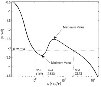
Table 1Variation of the roots of polynomial Ds with the small perturbation on oscillation amplitudes
Oscillation | Characteristic equations D(s) | Root 1 | Root 2 | Root 3 | Root 4 |
ω=ωn1= 1.06 rad/s A=An1+∆A=0.4343 | D(s)=s4+6.9853s3 +13.4365s2+7.8143s +13.7262 | –3.4916 + j0.3393 | –3.4916 – j0.3393 | –0.0010 + j1.0561 | –0.0010 – j1.0561 |
ω=ωn1= 1.06 rad/s A=An1-ΔA= 0.4257 | D(s)=s4+6.9850s3 +13.4655s2+7.8711s +13.9631 | –3.4937 + j0.3811 | –3.4937 – j0.3811 | 0.0011 + j1.0633 | 0.0011 – j1.0633 |
ω=ωn2= 2.54 rad/s A=An2+ΔA= 0.0317 | D(s)=s4+6.7993s3 +31.6659s2+43.5289s +162.5384 | –3.4038 + j3.7029 | –3.4038 - j3.7029 | 0.0042 + j2.5348 | 0.0042 – j2.5348 |
ω=ωn2= 2.54 rad/s A=An2-ΔA= 0.0311 | D(s)=s4+6.7952s3 +32.0632s2+44.3072s +165.7816 | –3.3937 + j3.7409 | –3.3937 – j3.7409 | –0.0039 + j2.5492 | –0.0039 – j2.5492 |
ω=ωn3=22.12 rad/s A=An3+ΔA= 0.0013 | D(s)=s4+2s3+494s2 +948.9s+3937.7 | –0.0229 + j22.0401 | –0.0229 – j22.0401 | –0.9763 + j2.6745 | –0.9763 – j2.6745 |
ω=ωn3=22.12 rad/s A=An3-ΔA= 0.0012 | D(s)=s4+1.9s3 +503.7s2+968s +4017.2 | 0.0281 + j22.2644 | 0.0281 – j22.2644 | –0.9768 + j2.6739 | –0.9768 – j2.6739 |
For simplicity, ∆A is considered as a hundredth of An. By using the numerical software, the roots of six characteristic equations are listed in Table 1 in accordance with Step 1 and Step 2. Table 1 shows that oscillation 1 (An1,ωn1)= (4.30×10⁻¹, 1.06 rad/s) is stable because four roots are located in LHP when A=An1+∆A, and root 3 and root 4 are located in RHP when A=An1-∆A. It also shows that oscillation 2 (An2,ωn2)=(3.14×10⁻², 2.54 rad/s) is unstable because root 3 and root 4 are located in RHP when A=An2+∆A. Similarly, oscillation 3 (An3,ωn3)= (1.25×10⁻³, 22.12 rad/s) is stable. The improved DF method predicts that the system has two stable oscillations and one unstable oscillation.
5.2. Simulation of multiple oscillations
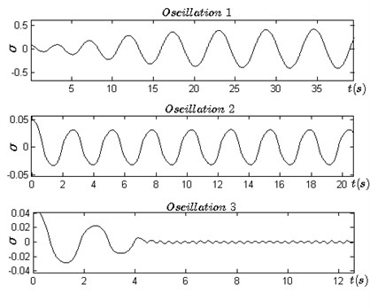
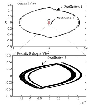
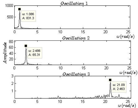
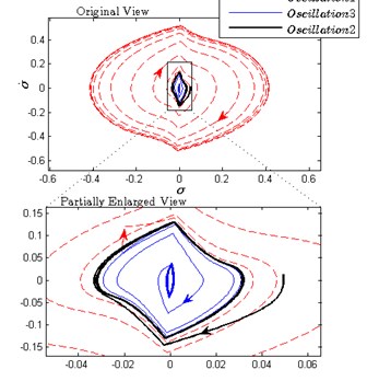
Simulation I is carried out to verify the three oscillations and their stability by using the numerical software. The state space in Eq. (10) is discretized by G=I+A×Te and H=B×Te. The controller updates its output u(t) once in every Te. The limit cycles and frequency spectrums can be plotted by using the data σ(t) in the steady-state process. The time series, phase portraits and frequency spectrums of σ are plotted in Fig. 3(a), (b) and (c), in which the oscillation amplitudes and frequencies can be measured directly.
Fig. 3a) Three types of motions in time domain, b) the phase portraits of the steady state of three oscillations, c) spectrum analysis of the steady state of three oscillations, d) stability of oscillation 2
a)
b)
c)
d)
Firstly, three sets of initial conditions (x1,x2,x3,x4)=(0.1, 0.008, 0,0), (x1,x2,x3,x4)=(0.01, 0.008, 0,0), (x1,x2,x3,x4)=(0.01, 0.006, 0,0) are selected to generate the three kinds of distinctly different motions in time domain (as shown in Fig. 3(a) and in phase plane σ-˙σ (as shown in Fig. 3(b). After the transient processes, the three motions approach their respective periodic oscillations. The measured amplitudes of the three oscillations are An1= 4.12×10⁻¹, An2= 3.18×10⁻²) and An3= 1.32×10⁻³. The frequency spectrum analysis is also made as shown in Fig. 3(c), by which we obtain spectrum components for each oscillation and measure the frequencies of the three oscillations: ωn1=1.09 rad/s, ωn2=2.49 rad/s and ωn3= 21.09 rad/s. Figs. 3(a), (b) and (c) demonstrate that the system exists three oscillations and it convergences to which oscillation depends on the initial conditions.
Next, the stability of the three oscillations needs to be verified. Obviously, oscillations 1 and 3 are locally stable. But the stability of oscillation 2 is not clear according to the above simulations. Fig. 3(d) shows the stability of oscillation 2 when disturbance is applied to the controller. Affected by external disturbances, the system is driven to escape oscillation 2 and approaches to oscillation 1 or 3.
Table 2Comparison of parameters of multiple oscillations estimated by DF method with the results of simulation I
Plant and sliding mode surface coefficients | Oscillations | Stability | Amplitude An | Frequency ωn (rad/s) | ||
Theory predict | Simulation I result | Theory predict | Simulation I result | |||
[a1,a2,a3,a4]= [2, 5, 12, 7] [c1,c2,c3,c4]= [4, 1, 0.5, 0] | 1 | Locally stable | 4.30×10⁻¹ | 4.12×10⁻¹ | 1.06 | 1.09 |
2 | Unstable | 3.14×10⁻² | 3.18×10⁻² | 2.54 | 2.49 | |
3 | Locally stable | 1.25×10⁻³ | 1.32×10⁻³ | 22.12 | 21.09 | |
M= 1; Te= 10 ms | ||||||
Hence, it shows that oscillation 2 is unstable. Finally, the estimated and simulated parameters of the three oscillations are listed in Table 2, and the theoretical results and the simulations are in good agreement. However, the errors between the theory predictions and simulations may mostly originate from the fundamental harmonic approximation of the DF method. In fact, the third and fifth harmonic which is approximately assumed to have been completely suppressed by the low-pass performance of W(s) may affect the phase angle of the closed loop. Hence, the accuracy of predictions depends on the intensity of residual high-order harmonics in σ(t).
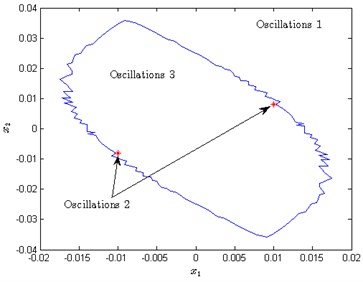
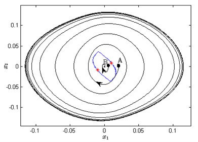
Fig. 4a) Attraction zones for each oscillation in x1-x2 plane, b) the relation between the attraction zones and the oscillation 1 and 3
a)
b)
The simulation indicates that the system converges to which oscillation depends on the initial conditions located in which region. In another word, each stable limit cycle has its own attraction region. However, predicting the attraction basin is difficult. The attraction region in the fuzzy system was plotted using simulations [24]. For simplicity, we only consider the influence of two state-variables x1 and x2 on the dynamic of the system. Equally spaced initial conditions are picked in the region R:{-0.02≤x1≤0.02,-0.04≤x2≤0.04,x3=0,x4=0}, and the steady-state processes corresponding to each point are simulated. We classified the processes as oscillation 1 or 2 or 3 based on their spectrum components. Subsequently, the region R can be divided into three attraction zones as shown in Fig. 4(a). The domain outside of the blue curve is the attraction zone of oscillation 1, and the domain in the blue curve is the attraction zone of oscillation 3. In addition, the attraction zone of oscillation 2 is very small which is represented as the only two red points.
The phenomenon of multiple oscillations can be interpreted as the inconsistent stability of the system, which is the significant difference compared with the linear system. The equivalent gain of the switching function M sign [-σ(t)] can be regarded as kn=2M/πAn[20]. kn changes along with the oscillation amplitude. Suppose that the system starts from point A as shown in Fig. 4(b), then the system is unstable and its trajectory is called the unstable spiral. In the motion, the gain kn continues to reduce when A is less than An1 until A equals An1. Similarly, when the system starts from point B as shown in Fig. 4(b), then the gain kn continues to increase when A>An3 until it converges to oscillation 3. Hence, the blue curve in Fig. 4(b) is similar with the watershed.
6. Elimination of undesired oscillation
According to the analysis above, the system may switch between oscillations 1 and 3 with the variation of external conditions. We hope to eliminate oscillation 1 due to its small equivalent gain which may lead to poor precision and weak robustness. Furthermore, the system could become the globally stable one if oscillation 1 can be eliminated.
6.1. Coefficient tuning method
The fact that φ(ω) crosses the line φ=-π three times leads to multiple oscillations. φ(ω) can be rewritten as:
where:
Assuming that the plant (as shown in Eq. (10) and sampling period are invariant, tuning the sliding surface is a feasible method to eliminate the undesired oscillation. In the following, we will discuss the influence of the sliding surface on φ(ω), and eliminate oscillation 1 by tuning the coefficients C=[c1,c2,c3,c4]. As shown in Fig. 2, if the minimum value of φ(ω) in the low-frequency band can be increased to more than –, then there is only one intersection corresponding to oscillation 3. Increasing or , or decreasing or will make rise faster in the low-frequency band. Hence, such tuning method could achieve the purpose. For simplicity, we only consider as an adjustable coefficient and also set 4, 1, 0, 2, 5, 12, 7 and 10 ms.
As shown in Fig. 5, the minimum value of in the low-frequency band increases with the variation of from 0.5 to 2. When 0.5 and 0.8, there exists three intersections between and the straight line . When 1.1, there remains only one intersection in the high-frequency band, and the system becomes a globally stable one. Table 3 also shows the relation among the parameters of oscillations, coefficient and zero placement. It is found that oscillation 1 is eliminated and there is little variation in the frequency of oscillation 3 when increases.
From the perspective of the phase-frequency characteristic of the sliding surface, we find the relations between and the number of oscillations. According to the zero placement, the damping coefficient is increased and the natural frequency is reduced with the increase of . Hence, could provide greater increase rate for at the lower frequency band with the increase of . Therefore, can be uplifted in the low-frequency band. The undesired oscillation 1 can be eliminated when the minimum value of is greater than .
Fig. 5Variation of curves φω with c3
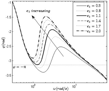
Table 3The relation among the coefficient c3, parameters of oscillations and zero placement
(rad/s) | (rad/s) | zero placement | |||
0.5 | 1.06 | 4.30×10⁻¹ | 22.12 | 1.25×10⁻³ | –1.0000 ± j2.6458 |
0.8 | 1.11 | 3.45×10⁻¹ | 23.80 | 1.70×10⁻³ | –0.6250 ± j2.1469 |
1.1 | – | – | 24.52 | 2.30×10⁻³ | –0.4545 ± j1.8520 |
1.4 | – | – | 24.88 | 2.80×10⁻³ | –0.3571 ± j1.6521 |
1.7 | – | – | 25.20 | 3.30×10⁻³ | –0.2941 ± j1.5055 |
2.0 | – | – | 25.36 | 3.90×10⁻³ | –0.2500 ± j1.3919 |
6.2. Verification for tuning method
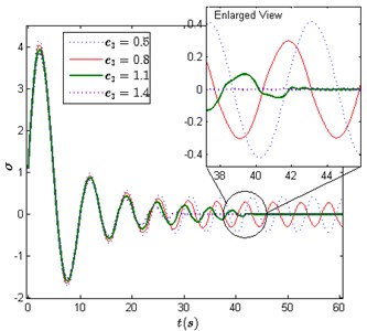
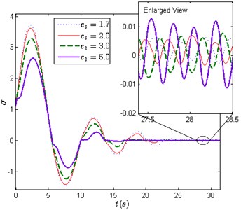
Simulation II is carried out to verify the stability of the tuned system when the initial condition is set as (0.1, 0.7, 0, 0) and is set as a number of different values. Fig. 6 shows the system responses in time series when equals to 0.5, 0.8, 1.1, 1.4, 1.7, 2.0, 3.0 and 5.0. When 0.5 and 0.8, the system convergences to oscillation 1 which is a large and slow periodic motion. When 1.1, the system convergences to oscillation 3 since oscillation 1 has been eliminated, and oscillation 3 becomes a globally stable oscillation.
Fig. 6a) System responses when c3 equals 0.5, 0.8, 1.1 and 1.4, b) system responses when c3 equals 1.7, 2.0, 3.0 and 5.0
a)
b)
In addition, the comparison of these responses in Fig. 6 shows that sufficient large can also improve system performances in overshoot and settling time. The results of the two performances are given in Table 4.
Table 4Overshoot and settling time
1.1 | 1.4 | 1.7 | 2.0 | 3.0 | 5.0 | |
Overshoot | 3.935 | 3.830 | 3.725 | 3.622 | 3.284 | 2.649 |
Settling time (s) | 42.1 | 29.73 | 24.69 | 22.01 | 18.91 | 16.58 |
7. Conclusions
This paper has presented a frequency-domain approach to analyze the stability, oscillation frequency and amplitude, and attraction zone of the reduced-order SM system by using an improved DF method. The method allows for the predictions of oscillation parameters in the coupled nonlinearities. The stability of oscillations can be determined by the pole placement; hence, the method is suitable for the minimum and non-minimum phase system. The analysis focuses on the multiple oscillations in a fourth-order system in which there exists one unstable and two locally stable oscillations. More specifically, the reduced-order SM controller and zero-order holder are the major cause of multiple periodic motions. Here, it should be pointed out that the system converges to which oscillations depends on the location of its initial condition, and a method to eliminate the undesirable oscillation by tuning coefficients is presented. The simulations in time domain support the prediction of multiple oscillations and their parameters. Although the inaccuracy of the estimation of oscillations cannot be neglected due to the inherent approximation of the DF approach, this study provides guidance for the design of the SM system.
References
-
Young K. D., Utkin V., Ozguner U. A control engineer’s guide to sliding mode control. IEEE Transactions on Control Systems Technology, Vol. 7, Issue 3, 1999, p. 328-342.
-
Fridman L. Singularly perturbed analysis of chattering in relay control systems. IEEE Transactions on Automatic Control, Vol. 47, Issue 12, 2002, p. 2079-2084.
-
Mobayen S. An adaptive chattering-free PID sliding mode control based on dynamic sliding manifolds for a class of uncertain nonlinear systems. Nonlinear Dynamics, Vol. 82, Issues 1-2, 2015, p. 53-60.
-
Rahman R., He L., Sepehri N. Design and experimental study of a dynamical adaptive backstepping-sliding mode control scheme for position tracking and regulating of a low-cost pneumatic cylinder. International Journal of Robust Nonlinear Control, Vol. 26, Issue 4, 2015, p. 853-875.
-
Gu B., Sheng V. S., Tay K. Y., et al. Incremental support vector learning for ordinal regression. IEEE Transactions on Neural Networks and Learning Systems, Vol. 26, Issue 7, 2015, p. 1403-1416.
-
Gu B., Sun X. M., Sheng V. S. Structural Minimax Probability Machine. IEEE Transactions on Neural Networks and Learning Systems, 2016, (in Press).
-
Saghafinia A., Ping H., Uddin M. Adaptive fuzzy sliding- mode control into chattering-free IM drive. IEEE Transactions on Industry Applications, Vol. 51, Issue 1, 2015, p. 692-701.
-
Lee H., Utkin V. Chattering suppression methods in sliding mode control systems. Annual Reviews in Control, Vol. 31, Issue 2, 2007, p. 179-188.
-
Kang H., Lee Y., Hyun C. Design of sliding-mode control based on fuzzy disturbance observer for minimization of switching gain and chattering. Soft Computing, Vol. 19, Issue 4, 2014, p. 851-858.
-
Sira-Ramirez H. Dynamic second-order sliding mode control of the hovercraft vessel. IEEE Transactions on Control Systems Technology, Vol. 10, Issue 6, 2002, p. 860-865.
-
Peng L., Zheng Z. Q. Sliding mode control approach with nonlinear integrator. Control Theory and Applications, Vol. 28, Issue 3, 2011, p. 421-426.
-
Boiko I., Fridman L., Iriarte R., et al. Parameter tuning of second-order sliding mode controllers for linear plants with dynamic actuators. Automatica, Vol. 42, Issue 5, 2006, p. 833-839.
-
Boiko I., Fridman L., Iriarte R. Analysis of chattering in continuous sliding mode control. Proceedings of the American Control Conference, 2005, p. 2439-2444.
-
Kim E., Lee H., Park M. Limit-cycle prediction of a fuzzy control system based on describing function method. IEEE Transactions on Fuzzy Systems, Vol. 8, Issue 1, 2000, p. 11-22.
-
Wu D., Chen K. Limit cycle analysis of active disturbance rejection control system with two nonlinearities. ISA Transactions, Vol. 53, Issue 4, 2014, p. 947-954.
-
Oliveira N., Kienitz K., Misawa E. A describing function approach to the design of robust limit-cycle controllers. Nonlinear Dynamics, Vol. 67, Issue 1, 2011, p. 357-363.
-
Huang Y., Wang Y. Steady-state analysis for a class of sliding mode controlled systems using describing function method. Nonlinear Dynamics, Vol. 30, Issue 3, 2002, p. 223-241.
-
Gao W. B., Wang Y. F., Homaifa A. Discrete-time variable structure control systems. IEEE Transactions on Industrial Electronics, Vol. 42, Issue 2, 1995, p. 117-122.
-
Plestan F., Moulay E., Glumineau A. Robust output feed-back sampling control based on second-order sliding mode. Automatica, Vol. 46, Issue 6, 2010, p. 1096-1100.
-
Rosales A., Boiko I. Disturbance attenuation for systems with second-order sliding modes via linear compensators. IET Control Theory and Applications, Vol. 9, Issue 4, 2014, p. 526-537.
-
Paul A. K., Mishra J. E., Radke M. G. Reduced order sliding mode control for pneumatic actuator. IEEE Transactions on Control Systems Technology, Vol. 2, Issue 3, 1994, p. 271-276.
-
Kang H. B., Shen Y. On limit cycle chattering in sliding mode control systems under the influence of sampling intervals based on describing function approach. The Journal of China Universities of Posts and Telecommunications, Vol. 23, Issue 1, 2016, p. 55-59.
-
Eason R., Dick A., Nagarajaiah S. Numerical investigation of coexisting high and low amplitude responses and safe basin erosion for a coupled linear oscillator and nonlinear absorber system. Journal of Sound and Vibration, Vol. 333, Issue 15, 2014, p. 3490-3504.
-
Aracil J., Gordillo F. Describing function method for stability analysis of PD and PI fuzzy controllers. Fuzzy Sets and Systems, Vol. 143, Issue 2, 2004, p. 233-249.
-
Krein P. T., Bass R. M. Multiple limit cycle phenomena in switching power converters. Applied Power Electronics Conference and Exposition, Fourth Annual IEEE, 1989, p. 143-148.
-
Page G. F., Gomm J. B., Douglas S. S. An algorithm for generating real describing functions. UKACC International Conference on Control, IEEE, 2012, p. 947-952.
-
Shen Y. Research on chattering and limit cycle adjusting for output feedback SMC based on frequency domain analysis. The 26th Chinese Control and Decision Conference, IEEE, 2014, p. 2465-2469.
-
Shen Y., Qiu Y. Y. On multiple limit cycles in sliding-mode control systems via a generalized describing function approach. Nonlinear Dynamics, Vol. 82, Issues 1-2, 2015, p. 819-834.
About this article
The authors gratefully acknowledge the financial support of National Natural Science Foundation of China under Grant No. 61403313 and the Natural Science Foundation Project of Chongqing under Grant No. cstc2014jcyjA40014.

