Abstract
The existing guided wavefield damage imaging theory is mainly Fourier transform-based wavenumber domain analysis, which essentially processes signals in a global sense and easily loses local information of structural damage. The current research on wavefield damage imaging methods focuses on flat plate-type structures, with few studies involving composite curved panels. By utilizing the ability of two-dimensional continuous wavelet transform (2D CWT) to amplify the singular components of the signal, it is introduced into spatial domain wavefield analysis to generate 2D CWT wavefields in composite curved panels. Furthermore, a damage imaging algorithm is constructed based on 2D CWT wavefield energy fusion. The results show that the algorithm can accurately image damage in composite curved panels. The novelty of this paper lies in conducting a spatial domain analysis of the guided wavefield for the purpose of damage imaging in composite curved panels.
1. Introduction
Composite materials are widely used in the aerospace field owing to their superior properties. Damage diagnosis of composite structures is crucial for timely detection of damage to ensure structural safety. There are numerous methods for damage diagnosis[1, 2], among which the guided wave-based method has become one of the most promising technologies due to its wide detection range and sensitivity to subtle damage [3, 4]. The scanning laser Doppler vibrometer (SLDV) has realized the full wavefield measurement, laying a solid foundation for accurate imaging of damage. Ruzzene [5] proposed a frequency-wavenumber domain filtering method for damage imaging. Kudela et al [6] developed an adaptive wavenumber filtering method. Local wavenumber analysis [7] and space-frequency-wavenumber analysis [8] were developed based on the short-space Fourier transform. The existing wavefield damage imaging is mainly Fourier transform-based wavenumber domain analysis, which essentially processes signals in a global sense and easily loses local information of structural damage. The research objects described above are all flat plate-like structures. For the curved panels, most studies focus on modal parameter analysis [9, 10], wave propagation characterization [11, 12], etc. A few studies use the sensor array method for damage localization in curved panels [13, 14], while the research on wavefield damage imaging of curved panels is relatively limited. In this paper, a damage imaging algorithm in composite curved panels based on two-dimensional continuous wavelet transform (2D CWT) is proposed to address the above issues.
The rest of this paper is organized as follows. Section 2 formulates the 2D CWT wavefield imaging method. Section 3 provides a numerical case of a CFRP curved panel with delamination to verify the feasibility of the proposed method. Sections 4 and 5 present the discussion and conclusions, respectively.
2. Description of the proposed methodology
2.1. 2D CWT
If f(x)∈L2(R2)is square-integrable, the 2D CWT can be defined as [15]:
where ‘*’ represents the complex conjugate; ψu,s,θ(x) denotes the shifted, scaled, and rotated version of 2D mother wavelet and is expressed as:
where u=(ux,uy) is the translation vector; s is the scale factor; r-θ is a 2D rotation matrix as:
The expression of Eq. (1) in the Fourier domain is:
where ‘^’ denotes the Fourier transform operator and ω is the spatial frequency vector.
The mother wavelet used in this research is a 2D Morlet wavelet, which is defined in the frequency domain as:
2.2. 2D CWT wavefields
The structure studied in this research is a cylindrical curved panel, as shown in Fig. 1: γ is the inner radius, d is the thickness, α is the angle crossed by the curved edge of the panel, W is the arc length, and L is the length of the straight edge. The wavefield signal is the radial displacement field on the panel surface and is denoted as v(x,t), where t∈[0,T] is the time of wave propagation.
Fig. 1Schematic diagram of the curved panel
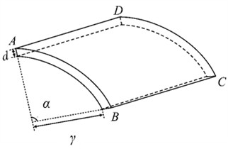
a) Stereoscopic view
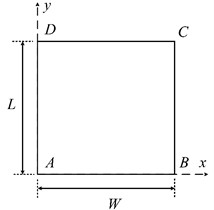
b) Plane view
In accordance to Eq. (1), the 2D CWT wavefield is obtained as:
To consider signal features in different propagating directions, the 2D CWT-wavefield is fused in the rotation angle domain as:
where Wθ(u,s,t) is called overall 2D CWT wavefield. In this study, rotation angles are taken from 0 to 15π/8 in an increment π/8.
2.3. Damage imaging based on 2D CWT wavefields
A wavefield energy time distribution function is defined as:
As the wave is excited and propagates in the panel, Et increases from zero to its maximum value (denoted as t0 at this time), and then maintains a stable state if there is no energy dissipation. At the stage where Et increases from zero to its maximum value, the wavefield signal is mainly concentrated around the excitation point and is not suitable for damage imaging. Therefore, in this research, the overall 2D CWT wavefields within the time window after Et reaches its maximum value are fused by calculating the energy map as:
Damage can be visualized in the overall 2D CWT wavefield energy map.
3. Method validation
The effectiveness of the 2D CWT wavefield damage imaging algorithm is verified in a simulated CFRP curved panel.
3.1. Sample description
Fig. 2 shows the schematic diagram of the simulated curved panel with single delamination. The parameters used in the simulation are as follows: L is 400 mm, d is 2 mm, α is 57.3°, γ is 400 mm. The specimen is composed of eight layers, with a thickness of 0.25 mm for each layer. The stacking sequence of these layers is [0°/90°/90°/0°]s. The delamination is located between the second and third layers from the top to the bottom surface, and its in-plane position is shown in Fig. 2, with a size of 30×30 mm2. The finite element model is shown in Fig. 3 with a total of 204800 elements and an element type of SC8R. The boundary condition of the curved panel is set as a free boundary constraint. Material properties of the composite curved panel are shown in Table 1. A 5-cycle sine pulse excitation signal with a central frequency of 50 kHz modulated by a Hann window is applied to the central node of the bottom panel surface. Upon the application of the excitation, 100 frames of radial displacement of each node on the top panel surface are collected, forming a continuous 1.5 ms radial displacement wavefield.
Fig. 2Schematic diagram of a CFRP curved panel with single delamination
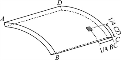
Fig. 3Finite element model of the composite curved panel
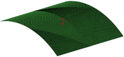
Table 1Material properties of the composite curved panel
Property | Symbol | Value |
Density / (kg∙m-3) | ρ | 1560 |
Elastic modulus / GPa | E11 | 128 |
E22 | 8.46 | |
E33 | 8.46 | |
Shear modulus / GPa | G12 | 3.89 |
G13 | 3.89 | |
G23 | 3.2 | |
Poisson's ratio | v | 0.322 |
3.2. Results
Fig. 4 shows a comparison between the original wavefield images and the overall 2D CWT wavefield images at some time, with the original wavefield on the left and the overall 2D CWT wavefield on the right. When t= 0.12 ms, the collision between waves and delamination generates small singular components. It is difficult to directly identify delamination from the original wavefield. However, the overall 2D CWT wavefield effectively amplifies the small singular components of the wavefield at the location of delamination. When t= 1.02 ms, the singular components of the wavefield caused by delamination are submerged in the principal wavefield components, but they are clearly presented in the overall 2D CWT wavefield.
Fig. 4Wavefield images and overall 2D CWT wavefield images

a)t= 0.12 ms

b)t= 1.02 ms
A 2D CWT wavefield image at a specific moment can achieve damage localization, but it is difficult to accurately determine the size and shape of the damage. Fig. 5(a) and (b) show the overall 2D CWT wavefield energy maps respectively formed by non-windowed and windowed fusion of the overall 2D CWT wavefields. From Fig. 5, it can be seen that accurate imaging of delamination has been achieved through image fusion. In Fig. 5(a), there is an energy concentration phenomenon at the excitation location, while in Fig. 5(b), it can be seen that energy concentration at the excitation location is eliminated through windowed fusion.
Fig. 5Overall 2D CWT wavefield energy maps
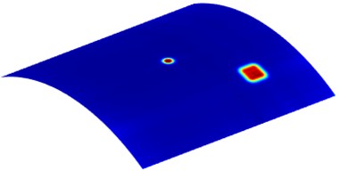
a) Non-windowed fusion
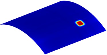
b) Windowed fusion
4. Discussion
The proposed algorithm relies on amplifying the damage-induced singularities within the guided wavefield. Various other types of damage, including open cracks, breathing cracks, corrosion, and so forth, can also generate singularities in the guided wavefield across different structural forms, such as flat and curved plates, as well as cylindrical structures like pipelines. Consequently, while the algorithm is demonstrated here through imaging delamination in a composite curved panel, it holds potential for detecting other types of damage in different structures following appropriate adjustments to the algorithm.
5. Conclusions
The 2D CWT is introduced into spatial domain wavefield analysis for the purpose of generating 2D CWT wavefields, which aims to amplify the singular components associated with damage. Based on the 2D CWT wavefield energy fusion, a damage imaging algorithm is constructed. The efficacy of the proposed 2D CWT wavefield damage imaging method is successfully verified through the identification of delamination in a CFRP curved panel. The obtained results clearly indicate that this method possesses the capability to precisely image delamination in composite curved panels.
References
-
G. Sha, W. Xiao, H. Zuo, M. Cao, M. Radzieński, and W. Ostachowicz, “Global-local damage localization and imaging in beam structures using laser-measured natural frequencies and guided wavefields,” Measurement, Vol. 236, p. 115061, Aug. 2024, https://doi.org/10.1016/j.measurement.2024.115061
-
G. Sha, M. Cao, W. Xiao, M. Radzieński, and H. Zuo, “Damage localization in beams based on the analysis of modal parameters,” Vibroengineering Procedia, Vol. 46, pp. 48–53, Nov. 2022, https://doi.org/10.21595/vp.2022.22999
-
S. Sikdar, W. Ostachowicz, and A. Kundu, “Deep learning for automatic assessment of breathing-debonds in stiffened composite panels using non-linear guided wave signals,” Composite Structures, Vol. 312, p. 116876, May 2023, https://doi.org/10.1016/j.compstruct.2023.116876
-
G. Sha, H. Xu, M. Radzieński, M. Cao, W. Ostachowicz, and Z. Su, “Guided wavefield curvature imaging of invisible damage in composite structures,” Mechanical Systems and Signal Processing, Vol. 150, p. 107240, Mar. 2021, https://doi.org/10.1016/j.ymssp.2020.107240
-
M. Ruzzene, “Frequency-wavenumber domain filtering for improved damage visualization,” Smart Materials and Structures, Vol. 16, No. 6, pp. 2116–2129, Dec. 2007, https://doi.org/10.1088/0964-1726/16/6/014
-
P. Kudela, M. Radzienski, and W. Ostachowicz, “Impact induced damage assessment by means of Lamb wave image processing,” Mechanical Systems and Signal Processing, Vol. 102, pp. 23–36, Mar. 2018, https://doi.org/10.1016/j.ymssp.2017.09.020
-
O. Mesnil, C. A. Leckey, and M. Ruzzene, “Instantaneous and local wavenumber estimations for damage quantification in composites,” Structural Health Monitoring, Vol. 14, No. 3, pp. 193–204, Dec. 2014, https://doi.org/10.1177/1475921714560073
-
Z. Li, C. He, Z. Liu, and B. Wu, “Quantitative detection of lamination defect in thin-walled metallic pipe by using circumferential Lamb waves based on wavenumber analysis method,” NDT and E International, Vol. 102, pp. 56–67, Mar. 2019, https://doi.org/10.1016/j.ndteint.2018.11.005
-
Z. Zhang, J. Pan, W. Luo, K. R. Ramakrishnan, and H. K. Singh, “Vibration-based delamination detection in curved composite plates,” Composites Part A: Applied Science and Manufacturing, Vol. 119, pp. 261–274, Apr. 2019, https://doi.org/10.1016/j.compositesa.2019.02.002
-
H. Li, Y. X. Hao, W. Zhang, S. W. Yang, and Y. T. Cao, “Vibration analysis of the porous metal cylindrical curved panel by using the differential quadrature method,” Thin-Walled Structures, Vol. 186, p. 110694, May 2023, https://doi.org/10.1016/j.tws.2023.110694
-
Q. Yuan, B. Kato, K. Fan, and Y. Wang, “Phased array guided wave propagation in curved plates,” Mechanical Systems and Signal Processing, Vol. 185, p. 109821, Feb. 2023, https://doi.org/10.1016/j.ymssp.2022.109821
-
N. Nanda and S. Kapuria, “Spectral finite element for wave propagation analysis of laminated composite curved beams using classical and first order shear deformation theories,” Composite Structures, Vol. 132, pp. 310–320, Nov. 2015, https://doi.org/10.1016/j.compstruct.2015.04.061
-
Q. Yuan, Y. Wang, Z. Su, and T. Zhang, “Quantitative damage evaluation of curved plates based on phased array guided wave and deep learning algorithm,” Ultrasonics, Vol. 137, p. 107176, Feb. 2024, https://doi.org/10.1016/j.ultras.2023.107176
-
J. Park and Y. Cho, “A study on guided wave tomographic imaging for defects on a curved structure,” Journal of Visualization, Vol. 22, No. 6, pp. 1081–1092, Sep. 2019, https://doi.org/10.1007/s12650-019-00589-y
-
G. Sha, M. Radzienski, R. Soman, T. Wandowski, M. Cao, and W. Ostachowicz, “Delamination imaging in laminated composite plates using 2D wavelet analysis of guided wavefields,” Smart Materials and Structures, Vol. 30, No. 1, p. 015001, Jan. 2021, https://doi.org/10.1088/1361-665x/abc66b
About this article
The authors are grateful for the partial support provided by the National Natural Science Foundation of China (No. 12102184), the Natural Science Foundation of Jiangsu Province (No. BK20210270), and the Graduate Research and Practice Innovation Program of Nanjing University of Aeronautics and Astronautics (No. xcxjh20230746).
The datasets generated during and/or analyzed during the current study are available from the corresponding author on reasonable request.
The authors declare that they have no conflict of interest.

