Abstract
Trajectory tracking and Object Localization in robots are developing rapidly, but the tasks are becoming increasingly complex and significantly increasing the range of tasks for robotic systems. Cognitive tasks in domestic, industrial or traffic conditions require not only the recognition of objects but also their evaluation by classifying them without direct recognition. One of such spheres are tunnels that are physically difficult for humans to reach and require diagnostics. In such an environment, it is difficult to globally define the direction and goal, so it is necessary to interpret the locally obtained information. To solve such a problem, sensor fusion is widely applied, but sensors of different physical natures do not allow to obtain the necessary information directly, so there is a great need to use AI to interpret and control the received information and generate the robot's trajectory [1]. Local navigation systems require a wide range of sensors [4]. Various cameras and time-of-flight LiDAR lasers are widely used. For the aforementioned reasons, an economical local trajectory generation and tracking system is being developed, one of the most important components for object recognition is the laser triangulation method. The essence of this method is that the camera reacts to the projection of the laser light in front of it and interprets the obstacle depending on its distortion. In this way, the camera's resources are more concentrated, and at the same time, a simple RGB camera is enough for this method. Also, this method is perfect in the dark, when the laser light is more pronounced. In this paper, the laser triangulation method will be reviewed in detail, evaluating its advantages and disadvantages.
1. Introduction
Laser triangulation is a widely utilized optical method due to its broad measurement range, high precision, and fast response time [8]. It has been extensively applied in surface scanning and object detection systems, particularly in mobile robots and industrial settings [9-11]. Laser triangulation employs a camera and laser configuration to measure distances and detect obstacles, offering flexibility in both stationary and mobile environments.
In obstacle detection applications, such as those described in [14], the method enables 3D scanning through the use of linear lasers and cameras. However, while effective for navigating through static environments, the method's response time-up to 10 seconds per scan-limits its use in dynamic scenarios. Another variation of this system, demonstrated in [11], employs a stationary laser and camera setup, suitable for 2D detection of obstacles, proving sufficient for applications such as wheelchair navigation.
In addition to obstacle detection, laser triangulation has been integrated into object recognition systems [10], where a mobile phone camera and laser are used to enhance navigation for the visually impaired. The method relies on template matching to measure distances with an average error of 1.25 cm, though challenges arise with lower resolution and varying object surface conditions.
Laser triangulation is also applied in industrial robotics for precise manipulation and inspection of objects [7, 9]. In these cases, the technology allows detailed surface scanning and accurate measurements in dynamic environments, though factors such as object size, color, and surface roughness can affect accuracy. Dual-laser setups have been used to overcome occlusions and achieve higher precision, particularly in the inspection of small components.
Overall, the versatility and accuracy of laser triangulation make it a valuable tool across various fields, though its limitations in dynamic environments and sensitivity to surface characteristics remain areas for further refinement.
2. Methodology for obstacle avoidance
One critical domain in need of autonomous navigation solutions is the inspection of channels that are physically hard for humans to access. This task presents multiple challenges. The enclosed nature of these environments significantly restricts external systems as well as capabilities. Additionally, the complete lack of natural light in tunnels there is risk of unexpected random Obstacles.
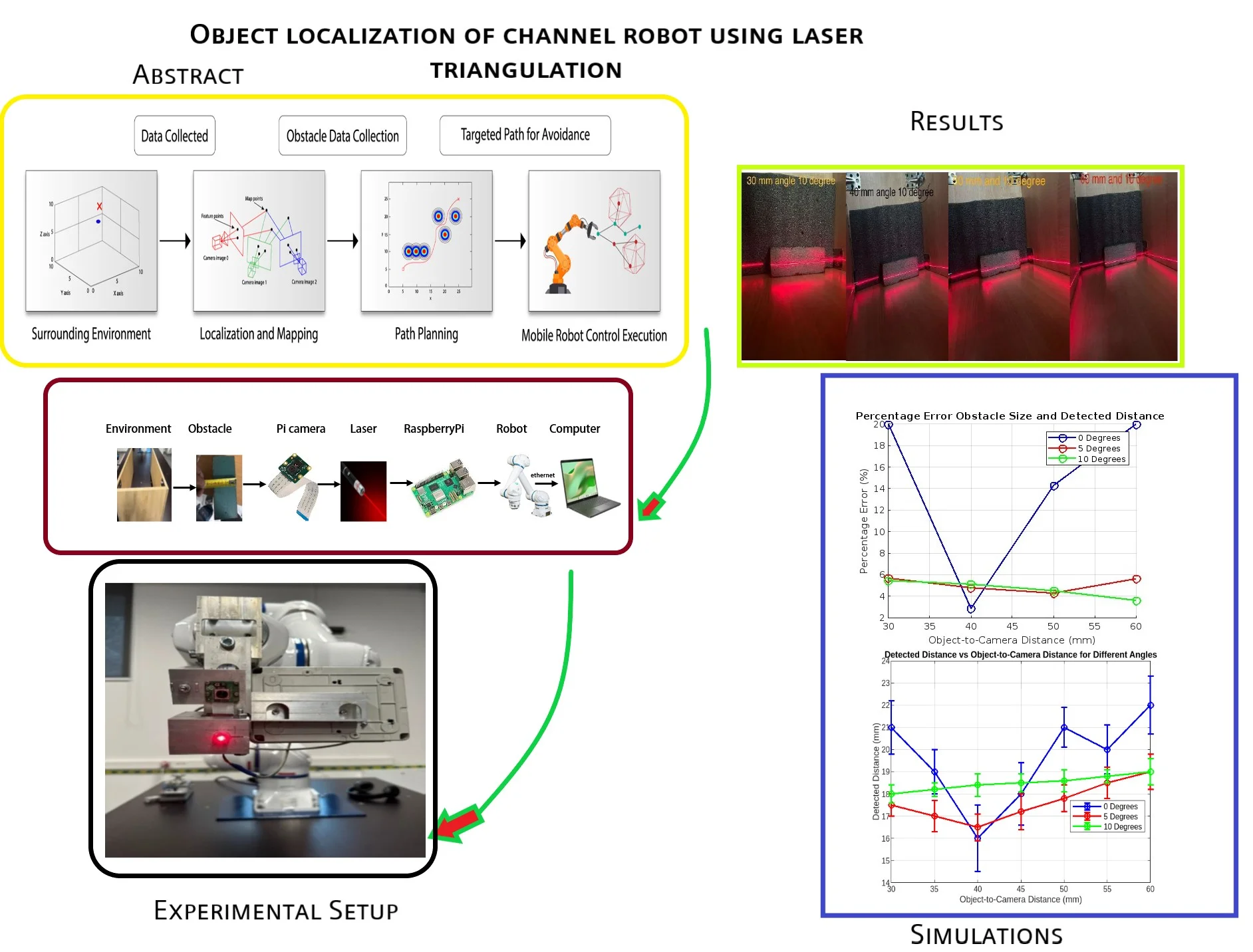
Fig. 1 illustrate the General algorithm Scheme for Robot Navigation Sytem. The robot gathers data about its surroundings using sensors such as cameras, lidar, or ultrasonic sensors. Once the data is collected, the robot uses it to localize itself in the environment and create a map. This helps the robot understand where it is in relation to obstacles or the localized objects. After mapping, the robot uses algorithms to plan a safe path Trajectory that avoids obstacles while reaching its target destination. Finally, the robot executes the planned path, adjusting its movements to follow the safest route and avoid collisions. This process ensures that the robot can navigate through its environment autonomously, avoiding obstacles along the way [1], [2].
In this Paper Laser Triangulation method is used Experimentally to Six-Axis Yakshawa Robot in order to detect Object Localization.
Fig. 1Implementation of obstacle avoidance for mobile robot

2.1. Design of laser triangulation
Before creating the experimental methodology, it is important to become more familiar with the applicable method. The main method is laser triangulation. This is an optical non-contact displacement detection method, where a laser beam, reflected at an angle from the surface, affects the corresponding pixels of the camera matrix, allowing the interpretation of the displacement size. The camera matrix responds to the optical signal and converts it into electrical signals [5] [6]. The surface displacement is obtained by processing these signals with a computer. There are two main types of laser triangulation: direct and oblique. These principles are illustrated in Fig. 2.
The direct method is more suitable for rough surfaces, while the oblique method is more appropriate for scanning smooth surfaces. Therefore, the angles α and β can be adjusted according to the situation to optimize the reliability of the measurements. According to the geometric principles of triangles, surface displacements can be expressed using formulas:
Fig. 2Schematic diagrams of laser triangulation direct on the right and oblique on the left [7]
![Schematic diagrams of laser triangulation direct on the right and oblique on the left [7]](https://static-01.extrica.com/articles/24617/24617-img2.jpg)
![Schematic diagrams of laser triangulation direct on the right and oblique on the left [7]](https://static-01.extrica.com/articles/24617/24617-img3.jpg)
2.2. Drawing up an experiment methodology for the projected system
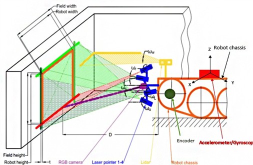
The designed system for recognizing the environment of an autonomous robot and generating a trajectory for underground tunnels consists of a set of several sensors. As shown in Fig. 3, a camera, linear projection lasers, and pseudo LiDAR will be used to identify objects. To track the direction and turn of the robot, an accelerometer and an encoder are used. The method of laser triangulation is provided for the object recognition system. The system consists of a chamber and four linear lasers. One red light laser whose focus center is aligned with the center of focus of the camera and which will be used to determine the distance to them and the dimensions of the object located on the ground. The next three lasers rotated at an angle will be green light and designed for obstacles located on the walls or hanging from the ceiling to observe.
We propose Pseudo Lidar and laser triangulation-based method for navigation in uncared for difficult to access tunnels. hardware of this system consists of Robot tank-type chassis, pseudo-Lidar with fixed angle ωw, one red light laser pointer rotated by angle ωg, three green light laser pointers rotated by angles ωr, ωl, ωu and RGB camera rotated by angle ωc.
Fig. 3Pseudo-Lidar and laser triangulation-based channel mobile robot navigation method
3. Experimental setup
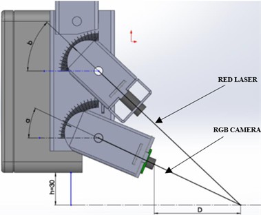
The aim of the first experiment is to find the optimal angle between the linear red light laser and the camera. This is influenced by the angle a and b as shown in Fig. 4. To estimate the optimal angle, you need to compare the real width of the object with the scanned width when the camera and laser focus centers coincide. When changing the angles, the measured distance D changes accordingly. The distance h of the sensor platform from the ground h is equal to 30 mm.
Fig. 4Experimental bench
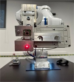
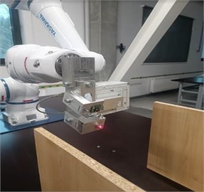
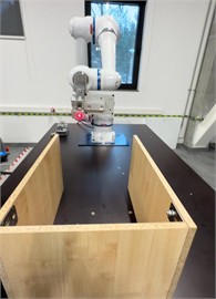
To conduct the experiment, a designed Six Axis Yakshawa robot tool is used for mounting the camera and laser and adjusting their angles relative to each other. The camera used is a Raspberry Pi 12 MP, and the laser is an RGB 12 650 nm, 5 V linear red laser. The Raspberry Pi 4 microcontroller is used for data processing and reading. The tool itself is mounted on a Yaskawa 6-axis robot arm, as shown in Fig. 6. The robot enables the simulation of mobile robot movement and allows for experiments with high repeatability.
Table 1Laser triangulation angle adjustment table
Distance to obstacle D, mm | Angle a, ° | Angle b, ° | Measured width of the obstacle p, mm |
60 | 29.5 | 48.5 | Xp,1 |
70 | 27 | 46 | Xp,2 |
80 | 25 | 43 | Xp,3 |
90 | 23.5 | 41 | Xp,4 |
100 | 22 | 39 | Xp,5 |
110 | 21 | 37 | Xp,6 |
120 | 19.5 | 35.5 | Xp,7 |
130 | 18.5 | 34 | Xp,8 |
140 | 17.5 | 32.5 | Xp,9 |
150 | 17 | 31 | Xp,10 |
160 | 16 | 30 | Xp,11 |
170 | 15.5 | 29 | Xp,12 |
180 | 15 | 28 | Xp,13 |
190 | 14 | 27 | Xp,14 |
200 | 13.5 | 26 | Xp,15 |
As previously mentioned, by changing angles α and β, the angle of the laser and camera is adjusted, which affects the measured distance. The value of the angle adjustment increment is 0.5 mm. During this experiment, the goal will be to determine how this distance affects the accuracy of the measured object width. Object widths selected are 5, 10, 50, and 100 mm, which are of considerable contrast, and it has been noted in the literature that these dimensions yielded different results. There is no longer a goal to examine widths greater than 100 mm, as such widths approach the dimensions of the mobile robot itself and the monitored area. The distance from which objects will be measured is chosen to range from 60 mm to 200 mm, in 10 mm increments. A distance of less than 60 mm may limit the robot’s ability to dynamically respond to obstacles, while a distance greater than 200 mm significantly magnifies the measurement area, thereby limiting the robot’s travel trajectory. Considering these measurement boundaries, a template table for the first experiment is provided in Table 1.
In this experiment, we have performed fifteen trials by adjusting the angles a and b according to the given data. The setup simulates a dark tunnel environment, minimizing light sources to highlight the laser projection. A tunnel model will be used, as shown in the 11th illustration. The dark contrast is expected to enhance the visibility of the laser beam and reduce the triangulation method’s dependence on the object's surface color.
After completing the fifteen trials with one object, the experiment will proceed with objects of different widths. The final results will be compared to determine the optimal configuration of angles a and b for object recognition in tunnel environments.
This experiment aims to find the best angle settings by running tests in low-light conditions ensuring precision in obstacle detection using laser triangulation.
3.1. Hardware
The Hardware consist of a Pi Camera and laser sensor, with data processing handled by a Raspberry Pi model B 4gb. The Pi Camera 12 Megapixels captures real-time images of the environment, while the laser offers precise distance measurements to detect obstacles. The Raspberry Pi processes this sensor data, fusing the information to determine Object and Obstacle positions and calculate safe navigation paths. The robot then uses this data to autonomously avoid obstacles as it moves, with the system monitored or controlled via a connected computer. Fig. 5 illustrate the hardware archtitecture and flow of data.
Fig. 5hardware architecture and data flow

Fig. 6Overall experimental setup
3.2. Software
Raspberry was programmed using Python which was used as the primary software for processing and managing the data, as well as for sensor integration, communication, and controlling the robot. Python's versatility and extensive libraries make it an ideal choice for robotics applications such as OpenCV etc.
4. Experimental results
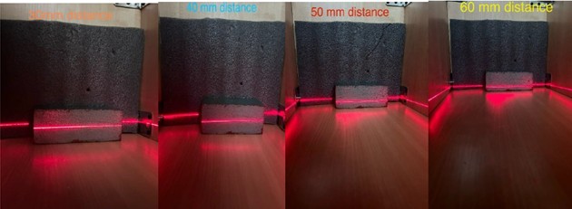
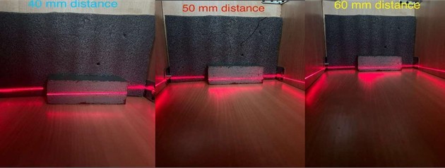
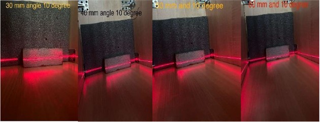
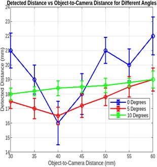
The experiment results were obtained by adjusting camera at different angle positions such as 0,5 and 10 degrees respectively. All fifteen tests were performed experimentally Fig. 7 shows the images when laser was subjected to object with 18 mm size of Obstacle. The amazing results were drawn.by changing the orientation of angle from 0 to 10.the optimal and true position was measured at the angle of 10. Table 2 represent the data obtained during the experiments tests.
Fig. 7Images captured at different a) at 0 degree b) at 5 degree c) at 10 degree
a)
b)
c)
Fig. 8Grey scale image and line calibration
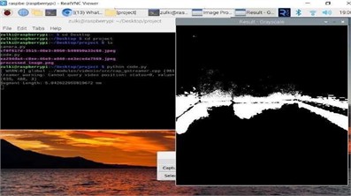
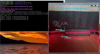
After obtaining the images taken by camera were inverted as Grey scale image to see clear vision of laser light and at the end each distorted line was measured in order to calibrate the obstacle size. Fig. 8 shows grey image and line calibration.
Table 2Experimental results
Object-to-camera distance (mm) | Obstacle size (mm) | Detected distance at 0° (mm) | Detected distance at 5° (mm) | Detected distance at 10° (mm) |
30 | 18 | 21 | 16.98 | 18.91 |
40 | 18 | 18 | 17.14 | 18.98 |
50 | 18 | 20 | 17.23 | 19.1 |
60 | 18 | 21 | 19.01 | 19.28 |
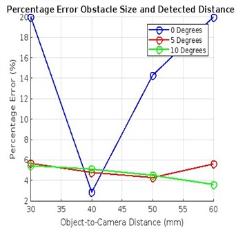
Fig. 9 shows the percentage error of Obstacle size and detected distance with varying object-to-camera distances with respect to camera tilt angles at 0°, the percentage error is highest approx. 20 % at both the closest (30 mm) and farthest (60 mm) distances. The error drops significantly (close to 0 %) at 40 mm, then increases again as the distance moves away from this point. At 5°, the error is relatively stable, staying within 4-6 % across all distances. The error slightly decreases with distance but remains relatively consistent. Similarly at 10°, the error is consistently the lowest, staying around 3-4 % throughout all distances. This suggests that the system performs better at higher tilt angles in terms of accuracy.
Fig. 9a) percentage error obstacle and detected distance, b) detected distance and object to camera distance
a)
b)
5. Conclusions
For the autonomous navigation and Object Localization of robot in tunnels, an experimental methodology has been developed. The experimental setup includes a tool equipped with a Raspberry Pi 12MP camera, a 650 nm camera, and a 5 V red line laser. This tool is mounted on a Yaskawa 6-axis robotic arm. A Raspberry Pi 4 microcontroller is used for data processing and acquisition. Additionally, a tunnel model with limited lighting is provided to simulate the working environment.
The experiment is consisting of four stages, changing the width of the scanned object to 5, 10, 50, and 100 mm, respectively. Each stage will include fifteen trials, adjusting the laser and camera angles so that the measurement distance ranges from 60 to 200 mm.
The laser triangulation method is a cost-effective technique for object localization, characterized by a wide measurement range, accuracy, and fast response time. However, it’s essential to remember that the accuracy of this method is highly influenced by the surface roughness and color of the object being scanned.
When implementing the laser triangulation method, it is crucial to properly adjust the positioning of the laser and camera relative to each other, either directly or at an angle. The direct alignment is advantageous for scanning rough surfaces and allows for the integration of multiple lasers to gather additional environmental information.
In the future, we can enhance the laser triangulation method by making it more intelligent and autonomous using AI and minimizing noise errors using Extended Kalman filter and CFAR (constant false alarm rate) for accuracy of signals.
References
-
M. A. H. Ali, M. Mailah, W. A. Jabbar, K. Moiduddin, W. Ameen, and H. Alkhalefah, “Autonomous road roundabout detection and navigation system for smart vehicles and cities using laser simulator-fuzzy logic algorithms and sensor fusion,” Sensors, Vol. 20, No. 13, p. 3694, Jul. 2020, https://doi.org/10.3390/s20133694
-
S. Jain and I. Malhotra, “A review on obstacle avoidance techniques for self-driving vehicle,” International Journal of Advanced Science and Technology, Vol. 29, No. 6, pp. 5159–5167, 2020.
-
J. A. Abdulsaheb and D. J. Kadhim, “Classical and heuristic approaches for mobile robot path planning: a survey,” Robotics, Vol. 12, No. 4, p. 93, Jun. 2023, https://doi.org/10.3390/robotics12040093
-
F. Gul, W. Rahiman, and S. S. Nazli Alhady, “A comprehensive study for robot navigation techniques,” Cogent Engineering, Vol. 6, No. 1, Jul. 2019, https://doi.org/10.1080/23311916.2019.1632046
-
J. G. D. M. Franca, M. A. Gazziro, A. N. Ide, and J. H. Saito, “A 3D scanning system based on laser triangulation and variable field of view,” in International Conference on Image Processing, Vol. 1, pp. 425–428, Jan. 2005, https://doi.org/10.1109/icip.2005.1529778
-
A. A. Adamov, M. S. Baranov, V. N. Khramov, V. L. Abdrakhmanov, A. V. Golubev, and I. A. Chechetkin, “Modified method of laser triangulation,” in Journal of Physics: Conference Series, Vol. 1135, No. 1, p. 012049, Dec. 2018, https://doi.org/10.1088/1742-6596/1135/1/012049
-
D. Ding, W. Ding, R. Huang, Y. Fu, and F. Xu, “Research progress of laser triangulation on-machine measurement technology for complex surface: A review,” Measurement, Vol. 216, p. 113001, Jul. 2023, https://doi.org/10.1016/j.measurement.2023.113001
-
Z. Nan, W. Tao, H. Zhao, and N. Lv, “A fast laser adjustment-based laser triangulation displacement sensor for dynamic measurement of a dispensing robot,” Applied Sciences, Vol. 10, No. 21, p. 7412, Oct. 2020, https://doi.org/10.3390/app10217412
-
E. W. Y. So, M. Munaro, S. Michieletto, M. Antonello, and E. Menegatti, “Real-time 3D model reconstruction with a dual-laser triangulation system for assembly line completeness inspection,” Advances in Intelligent Systems and Computing, No. 2, pp. 707–716, Jan. 2013, https://doi.org/10.1007/978-3-642-33932-5_66
-
R. Saffoury et al., “Blind path obstacle detector using smartphone camera and line laser emitter,” in 1st International Conference on Technology and Innovation in Sports, Health and Wellbeing (TISHW), pp. 1–7, Dec. 2016, https://doi.org/10.1109/tishw.2016.7847770
-
F. Utaminingrum, H. Fitriyah, R. C. Wihandika, M. A. Fauzi, D. Syauqy, and R. Maulana, “Fast obstacle distance estimation using laser line imaging technique for smart wheelchair,” International Journal of Electrical and Computer Engineering (IJECE), Vol. 6, No. 4, pp. 1602–1609, Aug. 2016, https://doi.org/10.11591/ijece.v6i4.9798
-
S. Klančnik, J. Balič, and P. Planinšič, “Obstacle detection with active laser triangulation,” Advances in Production Engineering and Management, Vol. 2, pp. 79–90, 2007.
-
G. Fu, P. Corradi, A. Menciassi, and P. Dario, “An integrated triangulation laser scanner for obstacle detection of miniature mobile robots in indoor environment,” IEEE/ASME Transactions on Mechatronics, Vol. 16, No. 4, pp. 778–783, Aug. 2011, https://doi.org/10.1109/tmech.2010.2084582
-
G. Fu, A. Menciassi, and P. Dario, “Development of a low-cost active 3D triangulation laser scanner for indoor navigation of miniature mobile robots,” Robotics and Autonomous Systems, Vol. 60, No. 10, pp. 1317–1326, Oct. 2012, https://doi.org/10.1016/j.robot.2012.06.002
About this article
The authors have not disclosed any funding.
The datasets generated during and/or analyzed during the current study are available from the corresponding author on reasonable request.
Muhammad Zulkifal: conceptualization, methodology, investigation, writing-original draft preparation, project administration, software, validation. Vytautas Bučinskas: supervision, funding acquisition, writing-review and editing. Andrius Dzedzickis: formal analysis, resources, writing-review and editing. Vygantas Ušinskis: data curation, software, writing-review and editing.
The authors declare that they have no conflict of interest.

