Abstract
With the continuous development of the coal mine industry in our country, the cross-section of the roadway is getting larger and larger. The widely used EBZ series roadheader cannot complete the roadway cutting operation with a large cross-section at one time, so it usually needs to move the equipment left and right to complete all its cutting tasks. This paper studies the intelligent control technology of large cross-section roadway cutting, which mainly solves the positioning and attitude determination technology of roadheader in the large cross-section, and offers an accurate shape-cutting control technology and a path planning technology using a lateral moving machine. This paper proposes to combine the signals of laser sensor and fiber-optic inertial navigation system to form a combined positioning and attitude determination system, so as to make use of the advantages and avoid the disadvantages of their respective systems, and improve the accuracy of roadheader positioning and attitude determination. A swing kinematics model of the cutting arm is established, based on which the precise motion control of the first roadway section cutting and the second roadway section cutting can be realized. A key parameter calculation model of roadheader lateral moving machine is put forward to calculate the operation parameters for roadheader lateral moving machine path planning. Finally, the experimental research on intelligent cutting control technology of large cross-section roadheader is carried out in 12307 intelligent heading face of Wangjialing Coal Mine. The results show that the positioning error of the combined positioning and attitude determination system proposed in this paper is between 50-90 mm in the -axis direction and between 25-45 mm in the -axis direction. The average attitude measurement error of heading angle is between 0.5 and 1.5°. This makes the technology appropriate for engineering use. The studied cutting control system achieves a cutting error of 25-50 mm for the first section, and a cutting error of 40-90 mm for the complete section. The complete section cutting error meets the ±100 mm cutting error requirement required in engineering. The intelligent cutting control technology of the lateral moving machine of the large-section tunnel boring machine studied in this paper can realize accurate cutting of the large-section tunnel of 5.6 meters. The research results of this paper provide a reference for the intelligent construction of heading faces.
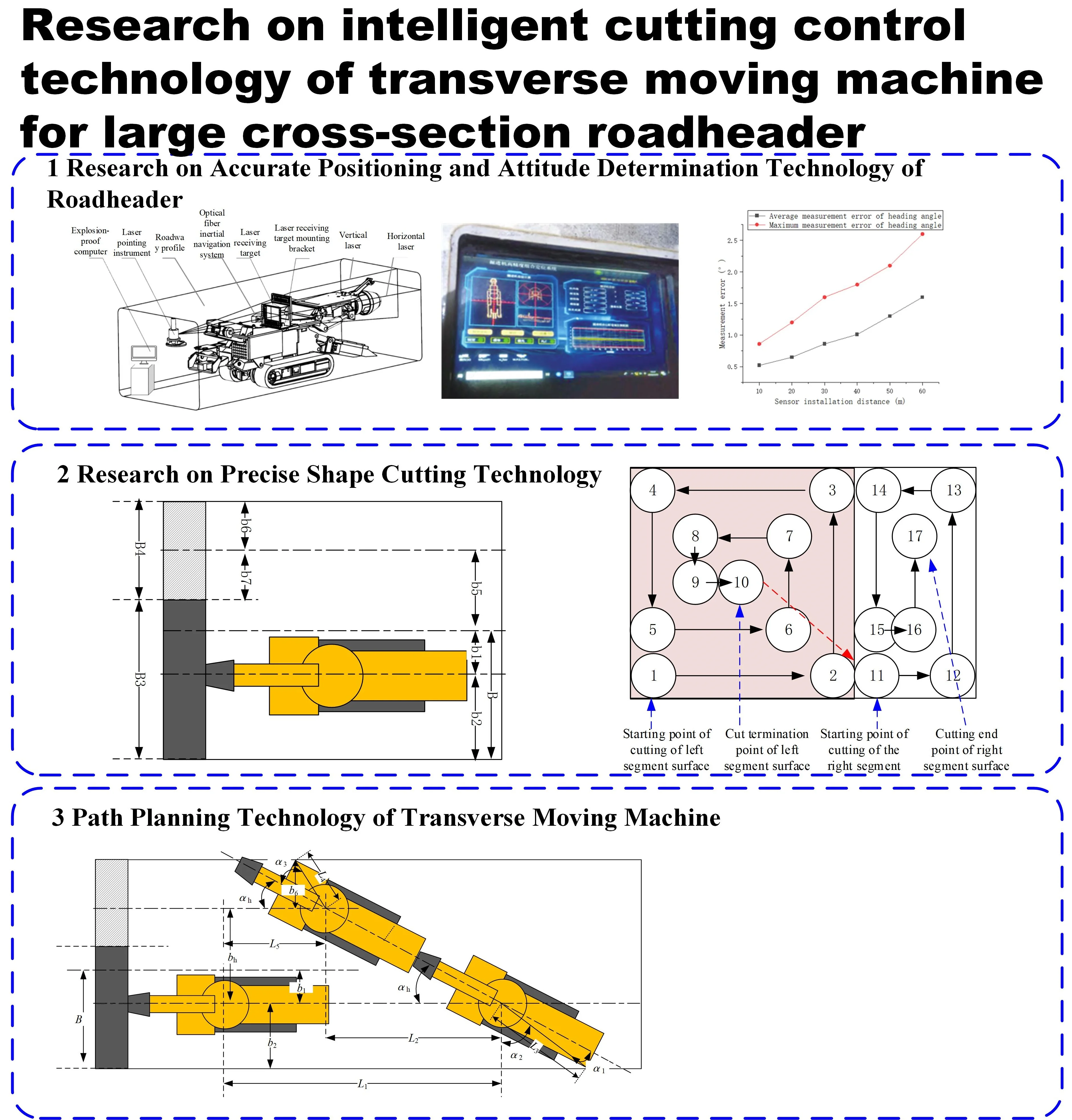
Highlights
- The positioning error of the combined positioning and attitude determination system proposed in this paper is between 50-90mm in the X-axis direction and between 25-45mm in the Y-axis direction.
- The average attitude measurement error of heading angle is between 0.5 and 1.5°.
- The studied cutting control system achieves a cutting error of 25-50mm for the first section, and a cutting error of 40-90mm for the complete section.
1. Introduction
With the continuous development of coal mine technology in China, the intelligent control technology of coal mine equipment has been continuously developed [1-4]. In recent years, experts and scholars have carried out extensive and in-depth researches on the intelligent control technology of roadheader.
The application of vision technology in heading face is studied in reference [5], and the application of vision technology in position and attitude monitoring, safety monitoring and intelligent control of a roadheader is analyzed. The sensitive relationship between different cutting state parameters and the change of cutting load is studied in reference [6], which provides support for intelligent cutting control and health diagnosis analysis of a roadheader. In reference [7], a memory cutting control technology of EBZ-series roadheader based on the digital twin drive technology is proposed to provide a new idea for the research on the intelligent cutting control algorithm of the roadheader. Based on the advanced wireless 5G technology and the latest electro-hydraulic control technology, a intelligent electronic control system is designed for a roadheader in reference [8]. It is realized that the cutting error limit of the intelligent electronic control system of roadheader is less than 40 mm. The literature [9] studies the environment awareness technology and self-walking path planning algorithm of coal mine intelligent equipment, which provides a theoretical support for the intelligent cruise operation of roadheader. A roadheader cutting control system with autonomous speed regulation is proposed in reference [10]. Compared with the conventional constant speed cutting control, the width specification deviation is reduced by 37 %, while the height deviation is reduced by 17 %, and the cutting control quality is improved. Reference [11] realizes the construction of digital twins in heading face, and puts forward a parallel intelligent control method to realize the all-element management and control of “personnel-equipment-roadway-environment” in heading face, which provides a new idea for intelligent autonomous operation of roadheader. A four-gear prediction and control method for the roadheader cutting head speed based on fuzzy mathematics is proposed in reference [12]. The roadway coal and rock identification method based on the infrared thermal image and the intelligent gangue avoidance cutting control strategy are proposed in reference [13]. This can effectively reduce the calorific value and fuselage vibration of the cutting mechanism. A method of rock wall hardness identification for roadheader based on the multi-source data fusion is proposed in reference [14]. The roadway coal and rock identification is realized by using vibration signals, oil pressure signals and current signals for the cutting head at the roadheader cutting arm.
The above documents contribute and refer to the research on intelligent systems of tunnel boring machines. However, the current positioning and attitude determination technology of tunnel boring machines is not mature enough, and the positioning accuracy in underground is low. There are few studies on the lateral movement control technology and secondary cutting and forming technology of tunnel boring machines for large-section tunnels.
Therefore, this paper carries out a research on the intelligent control technology for cutting large cross-section roadways, mainly solving the positioning and attitude technology, precise shaping and cutting control technology and lateral moving machine path planning technology for boring machines in a large cross-section.
2. Overall scheme of cutting control for roadheader moving machine
The positioning cutting width of EBZ200 roadheader is up to 5600 mm. Theoretically, the cutting of 5600 mm width roadway can be realized when the roadheader is in the middle of the roadway. However, in the practical application, it is found that the EBZ200 roadheader is difficult to complete all the cutting operations of the roadway above the width of 4800 mm when the fuselage is not moving. The main reasons are as follows:
(1) it is difficult to locate the roadheader, so as to ensure that the roadheader is always on the central axis of the roadway. If the position of the fuselage is offset to one side of the roadway, the cutting arm cannot completely cut the section of the roadway on the other side.
(2) the swing of the cutting arm rotates around the usual rotation axis. If the cutting range is too large, a flat cross section cannot be cut in front of the roadway, but a spherical cross section can be obtained.
(3) the width of the shovel plate is usually between 3200-3500 mm, if the fuselage is fixed, the coal and rock outside the range of 3500 m cannot be included in the shovel plate, so it is necessary to move the fuselage repeatedly to collect materials, and the process of repeatedly moving the fuselage will cause many damages to the bottom plate.
Schematic diagram of the operating range of the tunnel boring machine is shown in Fig. 1.
Fig. 1Schematic diagram of operating range of tunnel boring machine
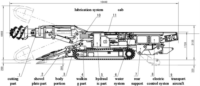
a) Cross-section of boring machine
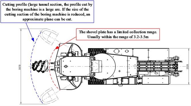
b) Schematic diagram of cutting section of boring machine
Therefore, for the large cross-section roadway, it is recommended to cut the cross-section on one side first, and then move to the other side for cross-sectional cutting after completing the cross-section cutting and material collection operation, as shown in Fig. 2.
Fig. 2Cutting process of cross-section of large roadway
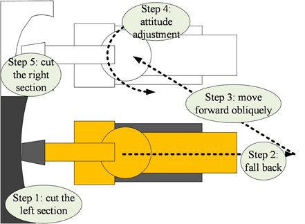
The intelligent cutting of large cross-section roadway driving needs to go through five steps:
(1) Large area section on the left.
(2) The roadheader retreated.
(3) The roadheader is oblique to the front.
(4) Attitude adjustment of roadheader.
(5) The rest of the right section is cut.
In order to realize the intelligent cutting control method for the above five steps in large cross-section roadway cutting, several key technologies need to be studied, including:
(1) Accurate positioning and attitude determination technology.
(2) The fixed shape cutting technology of two kinds of cross section. It includes the determination of the range of cutting section, the planning of cutting trajectory and the motion control of cutting arm.
(3) The technology of lateral moving machine path planning.
(4) Efficient communication technology. In this paper, 5G communication technology is selected to realize the efficient communication of intelligent equipment in the heading face.
3. Research on accurate positioning and attitude determination technology of roadheader
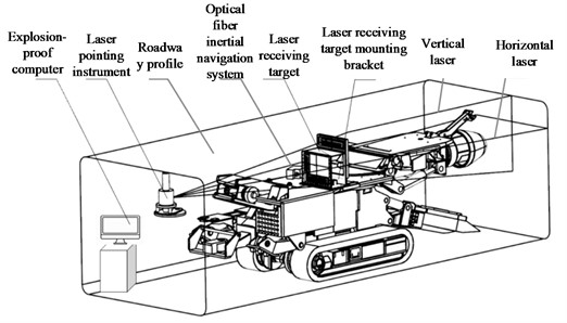
In view of the fact that the laser sensor roadheader positioning and attitude determination system is based on the absolute benchmark, because it has no cumulative error, but it is easily affected by environmental factors, such as dust, lighting conditions, shielding and so on. On the other hand, the roadheader positioning and attitude determination system of optical fiber inertial navigation has a high measurement accuracy and an independent system, that is not disturbed by external environment. However, the measurement deviation accumulates with time, this paper proposes to combine the signals of laser sensor and fiber-optic inertial navigation system to form a combined positioning and attitude determination system, so as to make use of the advantages of their respective systems, get rid of their disadvantages, and improve the accuracy of roadheader positioning and attitude determination, and its hardware composition is shown in the Fig. 3.
Fig. 3Components of intelligent road header
3.1. Laser positioning and attitude determination system
The laser sensor navigation system consists of a linear laser pointer, two laser-receiving horizontal targets, a dual-axis inclination sensor, a control box and a pose calculation computer. Each laser-receiving horizontal target consists of a main board, and a number of photoelectric sensors arranged in equal intervals are mounted on each main board. Each photoelectric sensor is located at a fixed position, and the spacing between every two photoelectric sensors equal. Two of the laser-receiving lateral targets are installed in the laser receiver, and the laser receiver is fixedly installed at the body of the boring machine.
The laser-receiving horizontal target is mainly responsible for measuring the deflection of the attitude of the boring machine body, and the dual-axis inclination sensor is mainly responsible for measuring the pitch and rolling conditions of the boring machine body. It is stipulated that the tunnel coordinate system takes the advancing direction of the boring machine as the -axis direction, while the tunnel floor pointing vertically to the roof is directed at the axis. The relationship between the , and axes constitutes the rule of the left-hand coordinate system, and the projection of the linear laser pointer fixed at the roof behind the tunnel on the plane of the tunnel floor is used as the origin of the tunnel coordinate system.
3.2. Light inertial navigation system
The LINS is composed of inertial measurement elements, a laser gyro and accelerometer. It uses the corresponding calculation algorithms and initial pose information to determine the position and attitude of the vehicle in real time. The laser gyroscope and accelerometer are installed along the three axes of the aircraft system. They can measure the angular velocity and acceleration of the carrier in the three axial directions in real time. After the conversion from the coordinate system, the attitude matrix and various attitude angles are calculated, namely, the deflection angle , the pitch angle , and the roll angle .
3.3. Combined positioning and attitude determination system
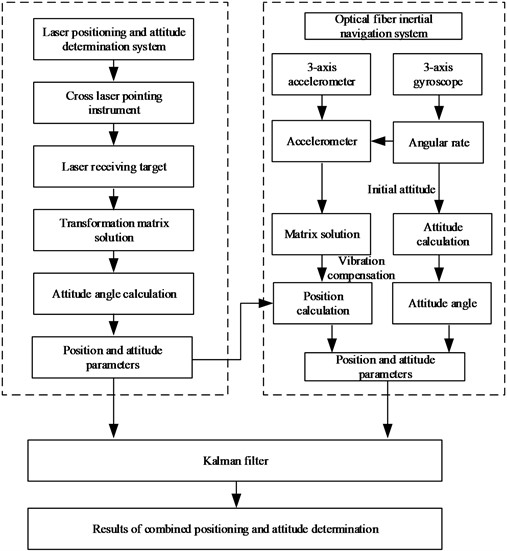
Firstly, the pose and position information of the roadheader is measured by the laser sensor, and then it is sent to the data processing module of the integrated positioning system. The attitude and position information of the roadheader is measured by the laser sensor to correct the inertial navigation drift of the optical fiber inertial navigation [15-16]. Its operation principle is shown in Fig. 4.
Fig. 4Software structure of integrated positioning and attitude determination system for roadheader
Let the system state equation be:
where: is the system noise matrix, and its covariance is ; is the driving matrix of the system noise matrix; is the state transition matrix.
Let the systematic observation model be:
where: is the observation data matrix; is the system matrix; and is the observation noise matrix.
For motion navigation in the presence of noise, a filtering algorithm is usually used to eliminate the error caused by system noise and measurement error during the motion trajectory tracking. The unscented Kalman filter adopts the Kalman linear filtering framework to make up for the disadvantages of nonlinear functions, and uses the unscented transformation when dealing with nonlinear mean problems such as covariance and mean. The UKF algorithm can approximate the probability density of a nonlinear function, and the posterior probability density of a state can be approximated through a series of certain samples, and does not adopt the form of an approximate nonlinear function. It does not ignore high-order terms and can play a good role in statistical nonlinear distributions. The algorithm can effectively compensate for the defect of one-level poor stability and low estimation accuracy of the extended Kalman filter. The steps of using the Unscented Kalman Filter algorithm to eliminate the motion trajectory tracking error of the robot are as follows:
(1) A group of data sampling points and their weights are obtained according to the UT transformation method.
(2) Solve for one-step prediction of sigma point sets:
(3) Calculate the one-step prediction of the state quantities of the equation of motion and its covariance matrix:
(4) Again, obtain a new set from Sigma sets according to the UT transformation:
(5) Import the newly generated Sigma set into the observation equation of motion to obtain the predicted value of the observation quantity:
(6) Obtain the weighted sum of the predicted values of the observations to obtain the mean and covariance of the predicted values of the equation of motion:
(7) Solve the Kalman gain matrix:
(8) Finally update the state and covariance of the equations of motion:
In terms of nonlinear filtering, the unscented Kalman filter does not require Taylor series expansion and the first n-order approximation, which makes the processing of nonlinear problems more accurate, so it is more suitable for mobile robot navigation problems.
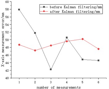
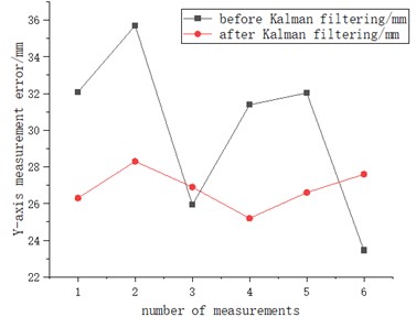
In order to verify the effect of Kalman filtering, the positioning error before and after Kalman filtering is tested, as shown in Fig. 5.
Test results show that after using Kalman filter, the -axis and -axis positioning errors are reduced significantly that confirms its profitability.
Fig. 5Measurement of positioning error before and after Kalman filtering
a)-axis measurement error
b)-axis measurement error
4. Research on precise shape cutting technology
The section cutting of large roadway needs to complete two cutting operations. The fuselage positioning of the roadheader is realized by the accurate positioning and attitude determination technology. Then, according to the first positioning of the roadheader, the width of the cutting section and the left and right swing range of the roadheader cutting arm are planned so that the roadheader could cut the required surface, and all the previous measurements are repeated for the second position of the roadheader. The left and right range of shaped cutting is shown in Fig. 6.
If the width of the roadway is set to , and the distance between the central axis of the roadheader and the central axis of the roadway is , the swing range of the cutting arm during the first fixed cutting is as follows:
A section with a width of is obtained after the first shaped cutting.
If the distance between the central axis of the second position of the roadheader and the central axis of the roadway is , then the swing range of the cutting arm during the second fixed cutting is:
After determining the cutting range, the motion path of the cutting arm can be planned according to the way shown in the following figure, which can be fed from the middle or from the floor, and the appropriate feed position needs to be selected according to the actual roadway conditions. Motion path planning of cutting arm for two sections is shown in Fig. 7.
Fig. 6Schematic diagram of left and right range of shaped cutting
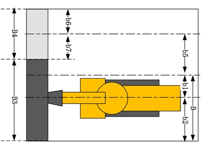
Fig. 7Motion path planning of cutting arm for two sections
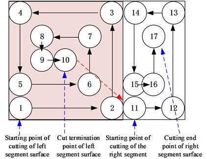
After completing the determination of the cutting section range and the planning of the cutting trajectory, it is necessary to control the trajectory of the cutting arm.
Since the cutting head is mainly realized through each group of oil cylinders, and the parameters that determine the position of the cutting head are the horizontal rotation of the cutting head , the vertical lifting and lowering of the cutting head , and the telescopic movement . Therefore, it is necessary to determine the horizontal and vertical rotation angles of the cutting head and the geometric relationship between the telescopic displacement amount and the movement position of the cutting head are the prerequisites for analyzing the forward and reverse motion of the cutting head. The vertical swing of the cutting head is as shown in Fig. 8.
Fig. 8Schematic diagram of vertical swing of cutting head
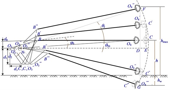
According to the structure of the cutting head, it is known that the size of does not change with the position of the cutting cantilever. From the geometric relationship of the mechanism, the following equation can be obtained:
According to the cosine theorem:
Set that when the axis of the cutting cantilever is in a horizontal position, the angle between and the horizontal plane is :
From the geometric relationship between the vertical swing of the cutting head and the height of the center of the cutting head from the ground, the following equation can be obtained:
When the cantilever axis is in a horizontal position:
It can be seen that when the cutting head swings vertically at an angle of , the length of the lifting oil cylinder is:
According to the geometric relationship in the figure, the vertical swing center is set as the initial position of cutting. It can be seen that when the cutting head is in the position, means that the maximum retraction amount of the push cylinder from the initial position during the vertical swing is , with the consideration of the retraction of the push cylinder:
where is the vertical swing angle when the cutting cantilever is in the highest position.
When the cutting head is in the position, means that the maximum extension of the push cylinder from the initial position is :
where, .
The displacement of the push cylinder when the cutting head is in any position is expressed as:
The schematic diagram of horizontal swinging of the cutting part is shown in Fig. 9.
Fig. 9Schematic diagram of vertical swing of cutting head
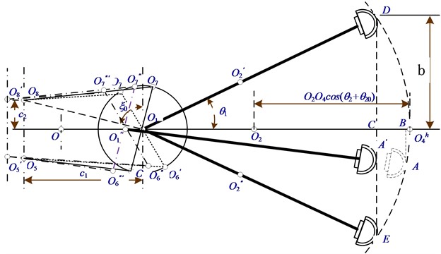
When the cantilever is in the neutral position, the installation position angle formed by the rear hinge point and the front hinge point of the hydraulic cylinder can be obtained as follows:
The distance between the center of the cutting head and the center line of the boring machine body is expressed as:
It can be obtained:
From this, the length of the two swing cylinders can be obtained as:
It can be seen from the figure that the displacement of the pushing cylinder when the cutting cantilever is in any position can be expressed as . According to the geometric relationship shown in Fig. 8, the equation can be obtained as follows:
The kinematic model of the boring machine cutting arm is established using the theory of robotics. The motion range of the boring machine cutting arm is calculated based on the kinematic model and the action stroke of each actuator is determined based on the cutting range.
Before carrying out the forward kinematics analysis of the cutting part, each coordinate axis and variable used for carrying out the forward kinematics analysis of the cutting head using the improved D-H method are described. The coordinate system in the improved D-H method is defined as follows:
In the coordinate system of the th joint, the axis coincides with the common perpendicular line between the th joint and the th joint, and points from the th joint to the th joint; the axis is determined by the right-hand rule; the axis coincides with the axis of the th joint. The definition of the improved D-H coordinate axis and parameters is shown in Fig. 10.
Fig. 10Definition of improved D-H axis and parameters
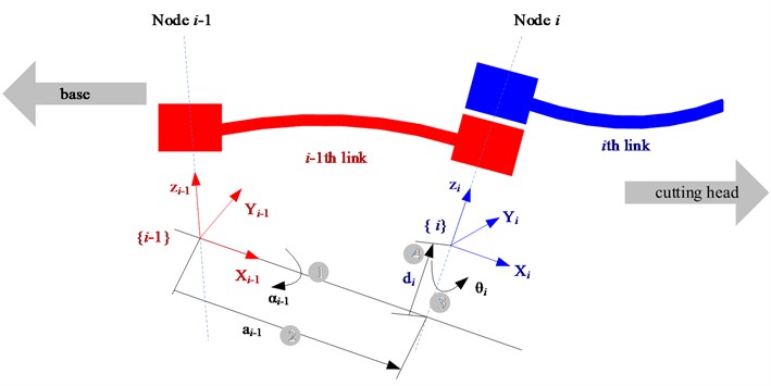
The parameters, physical meaning and types of the improved D-H method are shown in Table 1.
In the improved D-H method, the link transformation is expressed as the transformation from the th link coordinate system to the th coordinate system, and the expression is:
where, represents the rotation matrix; represents the position vector.
Table 1Parameters, physical meaning and types of improved D-H method
Parameters | Symbol | Definition | Category |
Joint angle | The angle from to rotation around | Rotary joint variable | |
Linkage offset | Distance from to measured along | Motion joint variables | |
Link length | Distance from to measured along | Constant | |
Connecting rod torsion angle | The angle from to rotation around | Constant |
First of all, several key coordinate systems are defined, and they are very important for understanding the position and motion of the roadheader and its components. The roadheader coordinate system () is the main coordinate system of the roadheader. It is used as a reference point to describe the overall position and direction of the roadheader; the roadway spatial coordinate system () is used to describe the space of the roadway, that is, the operating environment of the roadheader. The coordinate system of each mechanism of the roadheader () includes several different sub-coordinates, each coordinate system corresponds to a specific mechanism on the roadheader. The coordinate system of the turntable is used to locate the spatial position and direction of the turntable, the coordinate system of the cutting head of the roadheader is specially aimed at describing its position in the whole equipment, and the coordinate system of the telescopic part of the cutting head is used to describe the spatial position and telescopic movement pattern of the cutting head. The coordinate system for the cutting head of the roadheader is the coordinate system of the cutting head, which is the part of the actual cutting operation. Kinematic coordinate system of the roadheader is shown in Fig. 11.
Fig. 11Kinematic coordinate system of roadheader

The kinematics system of the roadheader is an open-chain (non-closed-loop) structure, which means that the mechanical parts are connected to each other according to a linear sequence without forming any closed loop. The key motion part of the system includes the cutting head, whose motion depends on several major mechanical movements:
(1) turntable rotation: this is the rotational motion of the cutting head on the horizontal surface, which is controlled by the rotation angle .
(2) cutting head rise and fall: this is the lifting movement of the cutting head in the vertical direction, which is controlled by the lifting angle .
(3) telescopic part movement: this involves the forward and backward movement of the cutting head, usually shown as the telescopic distance .
(4) roadheader fuselage movement relative to the roadway: this is the distance of the roadheader movement along the roadway as a whole, that is, the cutting feed .
These actions are performed in series, meaning that the execution of each action depends on the position and posture of the previous action. In order to accurately analyze and calculate the position and attitude of the cutting head, the Dmurh method is commonly used to analyze the joint motion in robot arms and similar mechanical systems [17-18]. The Dmurh method allows the parameterization of the joint displacement and rotation angle on the roadheader and converts these parameters into the specific coordinates and attitude of the cutting head relative to the roadheader and the roadway. This transformation is completed through a series of coordinate transformations, each of which corresponds to the action of a mechanism, so that the position and direction of each step of the cutting head can be accurately tracked. In the roadway coordinate system, the homogeneous transformation matrix for describing the cutting head is:
In the form:
where is the distance from the origin of the roadway coordinate system to the origin of the roadheader coordinate system on the axis; is the distance on the axis from the origin of the roadheader coordinate system to the origin of the turntable coordinate system on the axis; is the distance on the axis from the origin of the turntable coordinate system to the origin of the coordinate system of the cutting head on the axis; is the distance between the origin of the coordinate system of the cutting head and the origin of the coordinate system of the telescopic part on the axis. is the distance from the origin of the coordinate system of the telescopic part of the cutting head to the origin of the coordinate system of the cutting head on the axis; is the distance between the origin of the roadway coordinate system and the origin of the roadheader coordinate system on the axis; is the distance between the origin of the roadheader coordinate system and the origin of the turntable coordinate system on the axis; is the distance between the origin of the turntable coordinate system and the origin of the cutting coordinate system on the axis; is the height of the roadway.
If the coordinate is set at the center of the cutting head in the cutting head coordinate system, it can be transformed into the roadway coordinate system by the following formula:
In the form:
When the position and posture of the cutting head are known:
The motion parameters of the lifting, rotation and expansion of the cutting arm can be obtained by using the inverse kinematics analysis method:
According to the above research method, the range of the cutting section can be determined, the cutting trajectory planning and the motion control of the cutting arm can be realized. The kinematic model of the cutting head is established using the Matlab software, and the kinematic operation is simulated. The simulation of the cutting motion of large cross-section roadway is shown in Fig. 12.
Fig. 12Simulation of cutting motion of large cross-section roadway
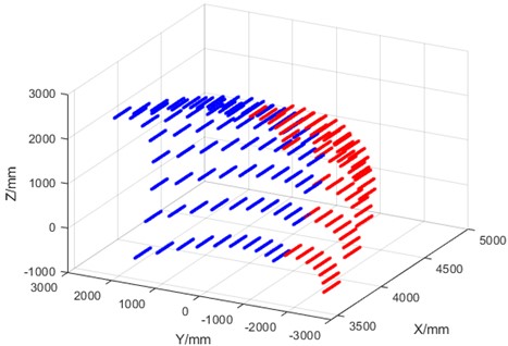
The blue part depicts the cutting area in the first section, where the cutting range is 2600~–500 mm, the red part depicts the cutting area of the second section, where the cutting range is –500~–2600 mm.
5. Path planning technology of transverse moving machine
5.1. Analysis of traverse process
The lateral movement process of the roadheader is shown in Fig. 13. After the roadheader completes the cutting operation at the left large section, it shall be withdrawn at the distance , then it shall rotate at the angle , then put the moving axial distance to the oblique front, then rotate at the angle , and finally move to the distance - forward to cut the rest of the right section. In this process, the roadheader realizes the lateral moving distance .
Fig. 13Process of lateral motion of roadheader
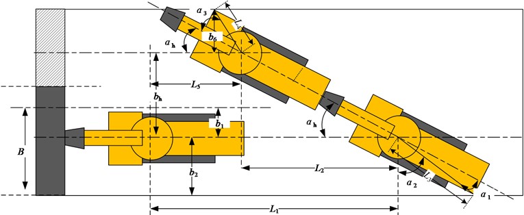
a) Schematic diagram of horizontal moving process
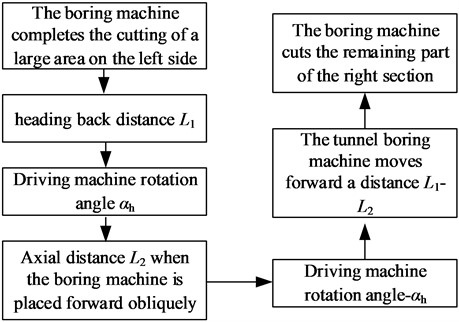
b) Horizontal moving flow chart
Several key parameters shall be determined here:
(1) Rotation angle :
When the roadheader rotates at the angle , it is necessary to ensure that the tail of the roadheader does not collide with the side of the roadway, that is why the limit value of the rotation angle is calculated according to the collision between the tail of the roadheader and the side of the roadway:
where: is the angle between the turntable and the tail end of the roadheader at the central axis, which is determined by the structure of the roadheader. is the distance between the roadheader turntable and the tail end.
(2) Oblique forward moving axial distance :
Because the roadheader needs to rotate at the angle after oblique forward movement, so that the roadheader is facing the roadway section, and the moving distance limit value is to ensure that the end angle of the shovel plate of the roadheader does not collide with the roadway section:
where: is the angle between the connecting line and the central axis at the end angle between the turntable and the shovel plate of the roadheader, which is determined by the structure of the roadheader. is the distance between the roadheader turntable and the end angle of the shovel plate.
The transverse distance of the roadheader can be obtained from the above type:
From the triangle relationship, the oblique forward moving axial distance can be obtained:
(3) Roadheader retreat distance :
The retreat distance satisfies ≥ oblique forward moving axial distance .
(4) Roadheader advance distance :
Finally, move the distance forward.
After determining the above four parameters, the trajectory of the roadheader can be determined.
5.2. Multi-objective optimization of traverse process parameters
Considering that the traversing process of the tunnel boring machine requires several processes: retreat, turn, advance, turn, and advance, it is necessary to take the minimum time in the traversing process and the shortest traverse retreat distance as the optimization goals, and the movement process of the tunnel boring machine does not collide with the coal wall as a constraint for multi-objective optimization [19].
Therefore, the rotation angle , the axial distance of oblique forward movement , the forward distance of the tunnel boring machine , and the traverse distance of the tunnel boring machine are taken as the design variables, namely:
An objective function is established with the minimum time in the traverse process and the shortest traverse retreat distance as the optimization goals:
where: is the time of the traverse process. is the withdrawal distance of the boring machine. There are:
The constraint conditions based on the fact that the heading machine does not collide with the coal wall during its movement are:
In this paper, a multi-objective optimization method based on genetic algorithm is adopted, that is, the ideal solution and effective solution of the optimization problem are obtained by using genetic algorithm.
The genetic algorithm has the temptation of real coding strategy, league selection mechanism, dynamic adjustment of crossover probability and mutation probability and introduction of adaptive operators. Set the population size at 100 and the termination algebra at 180.
Genetic algorithms are used to solve the optimal solutions of each single objective function in the above optimization problems, that is, the ideal solutions of multi-objective optimization.
Then the similarity priority ratio method is used to find out the similarity procedures between each effective solution and the ideal solution. Finally, the effective solution with the highest similar program to the ideal solution is regarded as the optimal solution for multi-objective optimization.
The optimal solution for the design variables calculated by the above method is:
Rotation angle 28.706°. The axial distance of oblique forward movement 2.4926. The advancing distance of the boring machine 2.8652. The traversing distance of the boring machine 1.365 m.
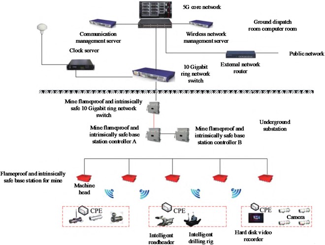
Fig. 145G network architecture of heading face
5.3. Stable and efficient communication technology in heading face
With the development of intelligent technology in coal mining, intelligent technologies such as digital twin technology and big data analysis technology have been applied and developed in coal mining. Intelligent control of roadheader in heading face shall interconnect underground and ground data, so a stable and efficient communication technology is required to support it. The intelligent cutting technology of horizontal movement of large cross-section roadway studied in this paper is applied to the underground 5G communication technology in coal mining.
A 5G base station and a CPE signal converter[20]are set up in the coal mine roadway, through which all kinds of sensing data and operation data of intelligent equipment such as intelligent roadheader, intelligent self-moving tail equipment, intelligent bolt trolley, intelligent conveyor belt and other intelligent equipment of the heading face can be sent to the centralized control room, thus the remote control of the intelligent equipment mentioned above can be completed in the centralized control room without the equipment dragging the signal cable. Tunneling work 5G communication network architecture is shown in Fig. 14.
It can be seen from the Fig. 14 that through the comprehensive coverage of the underground 5G network, the monitoring images of various cameras in the tunnel and the operating parameters of intelligent equipment such as intelligent boring machines can be transmitted back to the ground command center through the 5G network. When necessary, underground intelligent equipment can be remotely controlled from the ground command center. The high bandwidth of 5G networks can minimize delays in remote control and real-time data transmission.
6. Dynamic analysis of roadheader cutting operation
The pick-type cutting head is widely used in boring machines because of its high cutting efficiency and smaller quantity of broken particles. The cutting resistance and traction resistance of a single pick are respectively:
where: is the average value of the cutting impedance, N; is the width of the pick, m; is the average chip thickness, m; is the coefficient of brittleness and plasticity of coal; is the average section spacing, m; is the influence coefficient of the exposed free surface; is the influence coefficient on the shape of the front edge surface of the pick; is the influence coefficient of the cutting angle in case of the specific cutting energy consumption; is the influence coefficient of the chip diagram; is the mine pressure influence coefficient; is the pick installation angle, °; is the ratio of pick traction resistance to cutting resistance.
A force analysis on the pick is made with calculation of the load on the cutting head as shown in Fig. 15.
Fig. 15Force diagram of cutting head
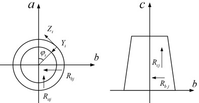
The vertical, horizontal and drilling direction components of the th pick on the cutting head are:
where: is the lateral resistance of the th pick, N; is the traction resistance of the th pick, N; is the cutting resistance of the th pick, N; is the position angle of the th pick, N.
The vertical load , the horizontal load , and the drilling direction load of the cutting head are respectively:
Due to whether the process of cutting coal and rock by the tunnel boring machine is complex, it is difficult to establish a dynamic model for analysis [22, 23].
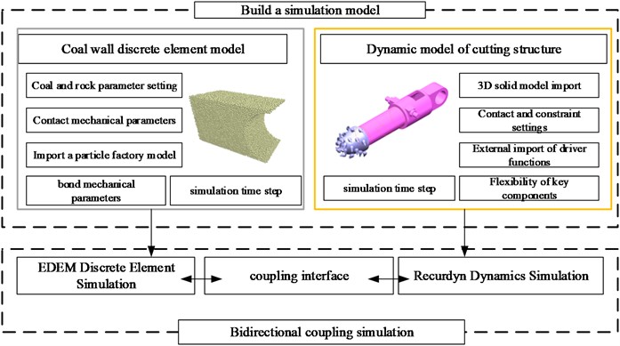
Due to the process of cutting coal and rock by the tunnel boring machine is complex, it is difficult to establish a dynamic model for analysis. Therefore, this paper uses the EDEM-RecurDYN joint simulation method to analyze the dynamic response of the cutting arm during the tunnel boring machine cutting coal and rock [24]. The EDEM-RecurDyn coupling calculation principle is shown in Fig. 16.
Fig. 16EDEM-RecurDyn coupling calculation principle
The cutting head speed was set at 60 rad/min and 120 rad/min to simulate different operating conditions. The swing speeds of the cutting arm were selected as 4 m/min and 8 m/min to evaluate the influence of changes in swing speed on cutting efficiency.
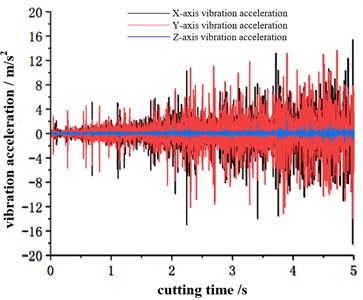
The first set of simulation parameters is that the rotating speed of the cutting head is 60 rad/min, and the swinging speed of the cutting arm is 4 m/min. As shown in Fig. 17, it is the vibration acceleration signal of the cutting arm when a common coal seam is being cut.
Simulation analysis of other groups shows that when the cutting head speed is 60 rad/min and the swinging speed is 4 m/min, the vibration intensity of the -axis is greater than that of the -axis. In this paper, the principle of comparing the -axis and the -axis is adopted, and the maximum value of the vibration acceleration is taken to represent the vibration intensity of the cutting head. Therefore, under this cutting parameter, the root-mean-square value of the vibration acceleration of the cutting head is 1.93, and the absolute average value is 1.26. When the cutting head speed is 120 rad/min, and the swinging speed is 4 m/min, the vibration intensity on the -axis is greater than that on the -axis. Therefore, under this cutting parameter, the root-mean-square value of the vibration acceleration of the cutting head is 2.07, and the absolute average value is 1.34. When the cutting head rotation speed is 60 rad/min and the swinging speed is 8 m/min, the vibration intensity on the -axis is greater than that on the -axis. Therefore, under this cutting parameter, the root-mean-square value of the vibration acceleration of the cutting head is 2.89, and the absolute average value is 2.05. When the cutting head rotation speed is 120 rad/min and the swinging speed is 8 m/min, the vibration intensity on the -axis is greater than that on the -axis. Therefore, under this cutting parameter, the root-mean-square value of the vibration acceleration of the cutting head is 2.05, and the absolute average value is 1.52.
When the rotating speed of the cutting head must be equal, the higher the cutting speed is, the greater the vibration intensity of the overall boring machine is. So, the swinging speed must be equal, because the higher the rotating speed of the cutting head is, the smaller the vibration intensity of the overall boring machine is. The swinging speed of the cutting head is 4 m/min, and the rotating speed is 60 rad/min. Compared with the traditional swinging speed of the cutting head of 8 m/min and the rotating speed of 120 rad/min, this value is very optimistic. If the swinging speed and rotating speed of the cutting head are increased at the same time, the vibration intensity will become slightly larger, that is, whether it is the -axis or the -axis, the vibration intensity of 8 m/min-120 rad/min will be slightly greater than the vibration intensity of 4 m/min-60 rad/min.
Fig. 17Vibration acceleration in x, y, and z axes of cutting head
7. Test and research
An experimental study on the intelligent cutting control technology of lateral moving machine of large cross-section roadheader was carried out in the Wangjialing Coal Mine, intelligent heading face #12307. This face is the first intelligent heading face of the China Coal Huajin Group. The shape of the roadway section is rectangular. The size is 5.6 m×3.55 m. EBZ series roadheader cannot carry out a full-section cutting, so the fuselage must be moved once for secondary cutting. The intelligent equipment configured in the intelligent heading face #12307 is shown in Fig. 18.
Intelligent Driving Face Equipment #12307 includes: EBZ200Z intelligent roadheader, belt transfer machine, fully automatic bolt drilling car, DZQ100/100/40 self-moving tail, intelligent dedusting fan, power station, centralized control center.
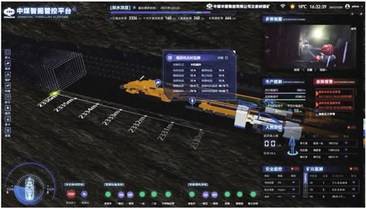
All equipment transmits signals to the centralized control center and ground command center through 5G communication technology [21]. The digital twin remote monitoring system of the centralized control center and the ground command center is shown in Fig. 19.
In the digital twin system of the heading face, you can clearly see the real-time underground monitoring pictures, the twin models and operating parameters of the boring machine and other equipment, and you can perform remote start and stop operations after each identification.
Fig. 18Configuration of intelligent heading face

Fig. 19Interface of digital twin system in centralized control center
8. Positioning technology test
The roadheader precise positioning and attitude determination technology studied in this paper is used for the combined positioning of the roadheader, as shown in Fig. 20.
Fig. 20Position and attitude monitoring of roadheader fuselage
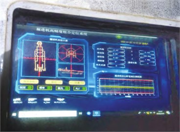
On the underground human-computer interactive equipment, attitude parameters such as horizontal azimuth, roll angle and pitch angle of the boring machine and the position information of the boring machine in the tunnel can be displayed in real time. The same data is also uploaded to the ground command center via the 5G network.
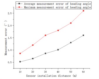
During the experiment, the laser positioning device is located at a distance of the 10 m-60 m from the roadheader to test the influence of different test distances on the positioning and attitude determination accuracy, so as to determine the optimal sensor installation position. Experimental results of positioning and attitude determination by the combined positioning method are shown in Fig. 21.
The test results show that the positioning error in the -axis direction is between 50 and 90 mm. The positioning error in the axis direction is between 25 and 45 mm. The average attitude measurement error of heading angle is between 0.5° and 1.5°. The positioning error of axis direction is lower than that of axis direction, and the positioning error of axis direction meets the requirement of ±100 mm positioning error in a coal mine. The positioning error of -axis and -axis and the attitude measurement error of heading angle will increase with the increase of the sensor installation distance. Generally speaking, the closer the sensor is installed, the higher the measurement accuracy will be. But the closer the sensor is installed, the higher the sensor readjustment rate will be as the roadheader advances.
Fig. 21Experimental results of positioning and attitude determination by combined positioning method
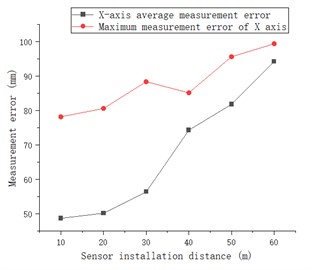
a)-axis positioning error
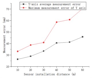
b)-axis positioning error
c) Heading angle attitude measurement error
8.1. Test of fixed shape cutting technique
Experiments are carried out on the fixed cutting control technology and transverse path planning technology studied in this paper. The width of the first cutting section is 3.65 m, and the width of the second cutting roadway is 1.95 m. The position of the fuselage of the first roadheader is set on the central axis of the section with a width of 3.65 m, that is, the roadheader is parked at a position of 0.98 m from the central axis of the 5.6 m roadway. After completing the first cutting, the roadheader shall move 2.8 m horizontally to complete the second cutting. The downhole monitoring system monitors the trajectory of the cutting head, as shown in Fig. 22.
Fig. 22Monitoring of motion trajectory of cutting head
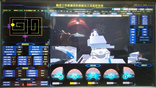
The underground human-computer interaction equipment can display the movement posture and parameters of the tunnel boring machine in real time, as well as conduct the trajectory planning for the tunnel cutting by the boring machine.
The cutting error data of the two sections are obtained by measuring the 10 cutting contours as shown in Fig. 23.
Fig. 23Cutting section error revealed by first test
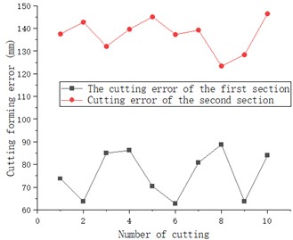
Fig. 24Corrected error of cutting section
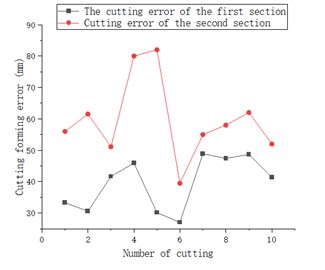
The initial test results show that the cutting error of the first section is between 60-90 mm and that of the complete section is between 130-150 mm. The complete section cutting error exceeds the requirement of ±100 mm cutting error in engineering. The main reason for the on-site analysis is that the cutting and swinging mechanism has a certain delay after receiving the stop command, resulting in over-digging, so through the program improvement, the profile setting value of the stop command will be generated if the roadway profile will become lower than 50 mm. The corrected cutting section error is shown in Fig. 24.
The modified test results show that the cutting error of the first section is between 25-50 mm, and the complete section cutting error is between 40-90 mm. The complete section cutting error meets the requirement of ±100mm cutting error existing in engineering.
9. Conclusions
This paper conducts a research on the intelligent control technology for cutting a large section roadway:
1) The precise positioning and attitude determination technology of laser and inertial navigation combination was studied. The test results showed that the positioning error in the axis direction was between 50 and 90 mm. The positioning error in the -axis direction was between 25 and 45 mm. The average attitude measurement error of heading angle was between 0.5 and 1.5°. This meets the needs of engineering use.
2) The precise shaped cutting control technology was studied and the cutting dynamics of the tunnel boring machine was analyzed. The test results showed that the cutting error of the first section was between 25 and 50mm, and the cutting error of the complete section was between 40 and 90 mm. The complete section cutting error meets the ±100 mm cutting error requirement actual in engineering.
3) The path planning technology for lateral movement of tunnel boring machines and the 5G communication technology in coal mines were studied.
The research limitations and future research plans of this paper are as follows:
1) Since the three-dimensional lidar technology has not yet been popularized in coal mining, the three-dimensional tunnel reconstruction technology based on a lidar shall be studied in depth.
2) The next research will focus on the impact of dust, light, etc. on the positioning and navigation system of the tunnel boring machine and solutions.
3) The technology of autonomous detection and adaptive repair of tunnel sections cut by tunnel boring machines is perspective for a future research.
References
-
C. Tian et al., “Discussion on development status and key technologies of intelligent driving equipment in coal mine,” (in Chinese), China Coal, Vol. 49, pp. 102–108, Jul. 2023, https://doi.org/10.19880/j.cnki.ccm.2023.07.013
-
F. Li et al., “Research on key technologies of coal mine intelligent excavation,” (in Chinese), Journal of Mine Automation, Vol. 49, pp. 33–41, Apr. 2023, https://doi.org/10.13272/j.issn.1671-251x.2022100062
-
J. Mao et al., “Research status and prospects of key technologies for intelligent rapid excavation in coal mines,” (in Chinese), Journal of China Coal Society, Vol. 49, pp. 1214–1229, Feb. 2024, https://doi.org/10.13225/j.cnki.jccs.2023.1424
-
J. Yang and Q. Gao, “Study on construction experience of intelligent tunneling system in coal mine,” (in Chinese), Coal Science and Technology, Vol. 50, pp. 303–309, Apr. 2022.
-
Y. X. Du et al., “Research status and development trend of visual processing technology for fully mechanized excavation systems,” (in Chinese), Journal of Mine Automation, Vol. 49, pp. 22–38, Nov. 2023, https://doi.org/10.13272/j.issn.1671-251x.2023090042
-
D. J. Wang et al., “Study on the sensitive relationship between cutting load and cutting state parameters of cantilever roadheader,” (in Chinese), Coal Engineering, Vol. 55, pp. 123–129, May 2023, https://doi.org/10.11799/ce202305021
-
X. H. Zhang et al., “DT-driven memory cutting control method using VR instruction of boom-type roadheader,” (in Chinese), Journal of China Coal Society, Vol. 48, pp. 4247–4260, Nov. 2023, https://doi.org/10.13225/j.cnki.jccs.2022.1741
-
L. Q. Zhang, “Design and research of new intelligent electronic control system for coal mine roadheader,” (in Chinese), Coal Technology, Vol. 43, pp. 245–248, Jan. 2024.
-
C. Y. Yang and X. Zhang, “Key technologies of coal mine robots for environment perception and path planning,” (in Chinese), Journal of China Coal Society, Vol. 47, pp. 2844–2872, Jul. 2022, https://doi.org/10.13225/j.cnki.jccs.2021.1130
-
X. H. Zhang et al., “Boom-type roadheader autonomous speed regulation cutting control system,” (in Chinese), Journal of Mine Automation, Vol. 49, pp. 80–89, Jan. 2023, https://doi.org/10.13272/j.issn.1671-251x.2022110066
-
Y. Wang, X. H. Zhang, and X. G. Cao, “Construction and parallel intelligent control method of digital twins in heading face,” (in Chinese), Journal of China Coal Society, Vol. 47, pp. 384–394, Jan. 2022.
-
Y. Yang et al., “Prediction for roadheader cutting head speed of different gears based on fuzzy mathematics,” (in Chinese), Coal Engineering, Vol. 54, pp. 172–176, Feb. 2022, https://doi.org/10.11799/ce202202030
-
D. Y. Zhang et al., “Experimental study on memory cutting of roadway cross-section containing gangue based on infrared thermography,” (in Chinese), Journal of China Coal Society, Vol. 46, pp. 3377–3385, Oct. 2021, https://doi.org/10.13225/j.cnki.jccs.2020.1052
-
L. F. Zhang et al., “Hardness recognition method of roadheader’s cutting rock wall based on multi-source data fusion,” (in Chinese), Journal of Vibration and Shock, Vol. 39, pp. 7–15, Jul. 2020, https://doi.org/10.13465/j.cnki.jvs.2020.13.002
-
X. Y. Yang, “Method of measuring roadheader’s body position and attitude based on photoelectric sensor,” Mechanical Design, Vol. 39, pp. 117–121, Jul. 2022.
-
L. Y. Tian et al., “Research on navigation system of roadheader based on combination mode,” (in Chinese), Chinese Journal of Engineering Design, Vol. 29, pp. 254–262, Feb. 2022, https://doi.org/10.3785/j.issn.1006-754x.2022.00.024
-
G. Guan, S. Y. Li, and M. R. Sun, “Kinematics analysis of robot for welding seam inspection of reactor pressure vessel based on DH method,” (in Chinese), Industrial Control computer, Vol. 36, pp. 73–74, May 2023, https://doi.org/10.3969/j.issn.1001-182x.2023.05.029
-
Y. Yang, T. Cao, and D. Liu, “A kind of calibration method for robot arm DH parameter by using calibration board,” (in Chinese), Journal of Mechanical Transmission, Vol. 41, pp. 178–181, Jun. 2017, https://doi.org/10.16578/j.issn.1004.2539.2017.06.035
-
J. Xu, X. Chen, W. Cao, and M. Wu, “Multi-objective trajectory planning in the multiple strata drilling process:A bi-directional constrained co-evolutionary optimizer with Pareto front learning,” Expert Systems with Applications, Vol. 238, p. 122119, Mar. 2024, https://doi.org/10.1016/j.eswa.2023.122119
-
R. Wei, L. Zhao, and C. J. Hu, “Research and practice of key technology of intelligent heading face in Wangjialing Coal Mine,” Journal of Smart Mine, Vol. 3, pp. 22–27, Sep. 2022.
-
Z. Y. Xu, “Study on automatic cutting method of cantilever roadheader in large cross-section coal roadway,” China University of Mining and Technology, China University of Mining and Technology, 2023.
-
C. Pany and G. Li, “Editorial: Application of periodic structure theory with finite element approach,” Frontiers in Mechanical Engineering, Vol. 9, p. 1192657, Apr. 2023, https://doi.org/10.3389/fmech.2023.1192657
-
C. Pany, “An insight on the estimation of wave propagation constants in an orthogonal grid of a simple line-supported periodic plate using a finite element mathematical model,” Frontiers in Mechanical Engineering, Vol. 8, p. 926559, Jul. 2022, https://doi.org/10.3389/fmech.2022.926559
-
P. V. Lade and A. V. Abelev, “Effects of cross anisotropy on three-dimensional behavior of sand. ii: volume change behavior and failure,” Journal of Engineering Mechanics, Vol. 129, No. 2, pp. 167–174, Feb. 2003, https://doi.org/10.1061/(asce)0733-9399(2003)129:2(167)
About this article
Project supported by National Natural Science Foundation of China (51874157).
The datasets generated during and/or analyzed during the current study are available from the corresponding author on reasonable request.
Qin Wenguang is responsible for writing the full text, Cheng Kai is responsible for experimental research, and Wang Biao is responsible for theoretical research.
The authors declare that they have no conflict of interest.
