Abstract
In order to improve the design level of pre-stressed hollow slab bridge beams, the airport 1# bridge was taken as the research object to study on the influence of guardrails on the mechanical properties of pre-stressed hollow plate beam bridges. On the basis of conducting overall structural verification, a solid model was established to analyze the influence of bridge deck guardrails on the mechanical behavior of cast-in-place joints in hollow slab bridges. Research shows that the maximum deflection and the maximum bending moment internal force decreases by 40 % and 14.5 %, respectively when taking into account the stiffness of the guardrail. However, the maximum shear force of the hollow slab edge joint and middle joint increases by 75 % and 14.5 %, respectively. The maximum shear force increases by 35.62 % when the height of the guardrail increases from 0.5 m to 2 m. The results indicate that the influence of bridge deck guardrails on the shear performance of slab hinge joints should be considered during the preliminary design stage of such bridges. The research results can provide reference for such structures.
1. Introduction
In recent years, highway engineering has achieved vigorous development [1], as the important structures along highways, bridges have been increasingly expanded in construction scale [2]. The hollow slab girder bridges are widely used in small and medium span bridges due to their many advantages (e.g. simple construction, low building height, convenient construction, low cost, etc.) [3]. However, the hollow slab bridges usually suffer from various diseases (e.g. bottom plate cracking, hinge joint cracking, bridge deck damaging, etc.) during the service period. Among them, hinge cracking is the most typical [4]. This article establishes a physical simulation model to analyze the influence of bridge deck guardrails on the mechanical behavior of cast-in-place joints in hollow slab bridges. Which can provide reference for the design of hinge joints at the edge of hollow slab beam bridges.
2. Project overview
2.1. Project overview
This project is located on Bishui Avenue in Dongxihu District, Wuhan City. Bishui Avenue spans the open channel of the Airport River. The starting point of the open channel upstream is about 2.2 km away from this project. The normal water level of the airport river is from 17 m to 17.5 m, and the low water level is from 15 m to 15.5 m. Low water level occurs every winter (September to April of the following year). The water level of the airport river in the 50 year rainstorm is about 19.3 m, the planned flow of the airport river is 394 m3/s, the current flow is 187 m3/s, and the planned maximum control water level is 19.5 m. The flow capacity where 1# bridge located is approximately 411 m3/s, which is greater than the planned flow of the airport river.
2.2. Finite element modeling
The half-span solid element model of the Airport 1# Bridge was established with the universal finite element software ABAQUS (see Fig. 1). The edge span sidewalk slab in the finite element model was directly applied by gravity. Both concrete and bearings were simulated using C3D8R eight node solid elements.
Fig. 1The finite element model
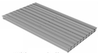
a) With guardrails
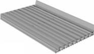
b) Without guardrails
3. Overall structural design and verification
Airport river 1#bridge is a pre-stressed concrete hollow slab bridge with a span of 3×16.5 m and a width of 30 m. The height of the hollow slab beam is 0.85 m, and the width of a single slab is 1.25 m. The boards are connected to each other in the form of hinge joints. The top of the slab is made of C50 cast-in-place waterproof concrete layer with a thickness of 15 cm. The bridge adopts a row type pier and pile foundation. The diameter of the pier column and the pile diameter are 1.2 m and 1.3 m, respectively.
Used Bridge Doctor software to verify the overall stress of the structure. Firstly, the bending moment and internal force under basic combination, long-term combination, and short-term combination working conditions were calculated according to the current regulations [5]. And the maximum bending moment and bearing capacity of the main beam under the most unfavorable combination condition were shown in Fig. 2. Results showed: the maximum positive bending moment (1743 kN.m) and the maximum negative bending moment (–141 kN.m) both were less than the corresponding bending strength (2172 kN.m and –879 kN.m). The maximum internal force of each section was less than the resistance. In addition, the maximum shear force at the fulcrum was 698 kN, and the shear bearing capacity was 1590 kN. The maximum internal force of each section was less than the resistance.
Fig. 2The maximum bending moment and bearing capacity under unfavorable working conditions

The normal section stress and oblique section stress of the main beam under frequent and quasi permanent combinations was analyzed. The minimum stress at the lower edge of the structure under frequency combination was located at the mid span (–1.51 MPa), and that under quasi permanent combination is located at the edge pivot point (–1.69 MPa). Both were less than the allowable value of in the specification (–1.85 MPa). The maximum tensile stress of the main beam was located at the fulcrum (–0.32 MPa), which was less than the allowable value in the specifications (–1.33 MPa).
In addition, the maximum deflection of the main beam under vehicle load was 6.4 mm with the Bridge Doctor software, which was less than the allowable value (see Eq. (1)) specified in the current regulations [5]:
where, [w] was the allowable value, l was the span.
In summary, the ultimate bearing capacity and normal service limit state of Airport 1# Bridge can meet the requirements of the specifications, and the overall mechanical performance of the structure is fine.
4. The influence of guardrails on the mechanical properties of hollow slab beam bridges
According to research [6], guardrails are the main factor affecting the stress performance of hinge joints in hollow slab bridges. Shear force at the hinge joint of hollow slab is one of the main mechanical indicators for evaluating the mechanical performance of hollow slab structures. The shear force changes at the board joint under the working conditions of no guardrail and with guardrail was analyzed. Then, the shear force variation at the plate joint under different guardrail heights was studied in this paper.
4.1. Calculation of shear force on the contact surface of board seam
The upper structure of this bridge adopts prefabricated assembled hollow slab beams with three spans. The boards are connected to each other in the form of hinge joints. The top of the slab adopts C50 cast-in-place waterproof concrete cast-in-place layer to form a continuous bridge deck. Joint cracks were one of the most typical diseases of this type of bridge. The impact of bridge deck guardrails is often overlooked when analyzing the overall design of bridges of the same type. To date, there are few studies on the influence of bridge deck guardrails on the mechanical properties of hinge joints. The mechanical influence of bridge deck guardrails on the hinge joints of prefabricated hollow slabs was analyzed using finite element numerical simulation methods based on the Airport 1# Bridge.
The shear compression calculation formula for hollow slab hinge joints [7] in European standards was adopted in this paper.
Previous research has shown that the shear strength of hinge joints is actually determined by the shear strength of the contact surface between hinge joints and hollow slabs. Currently, there is a lack of corresponding specifications for hinge joint shear verification in China, while European standards consider factors such as roughness of the contact surface, reinforcement ratio, reinforcement angle, and contact surface axial force. Therefore, the compression shear verification on the contact surface between hinge joints and hollow slabs was conducted according to European standards in this paper, just as reference 7:
where, Vcd devoted the shear force between the hollow slab and the hinge joint contact surface (kN), [V] devoted the maximum allowable shear force between the contact surface of the hollow slab and the hinge joint (kN), c and μ devoted the coefficients, which were related to the roughness of the contact surface, taking 0.45 and 0.7, respectively. Ac and As devoted the contact surface concrete area and steel reinforcement area, respectively (m2), ft and fy devoted the design values of tensile strength for concrete and steel bars, respectively (kPa), N devoted the axial force of the contact surface (kN), a devoted the angle between the bent steel bar and the interface (°).
4.2. The influence of guardrail stiffness on structural mechanical properties
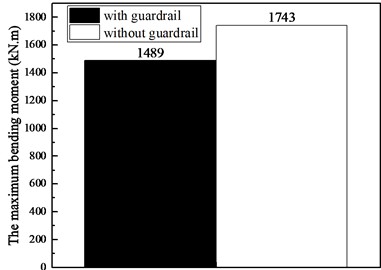
Figs. 3 and 4 reflect the maximum deflection and maximum bending moment internal forces with the guardrail and without the guardrail, respectively.
The maximum deflection of the structure was about 2.5 cm when ignoring the stiffness of the guardrail. And that decreased to 1.5 cm (with a decrease of 40 %) after considering the stiffness contribution of the guardrail. This was because the overall stiffness of the structure increased and the deformation decreased after considering the stiffness of the guardrail. In addition, the maximum bending moment the structure was about 1743 kN.m when ignoring the stiffness of the guardrail. And that decreased to 1489 kN.m (with a decrease of 14.5 %) after considering the stiffness contribution of the guardrail.
The overall force and deformation of the structure with considering guardrails in finite element models was smaller than that without considering guardrails in finite element models. Therefore, the influence of guardrail stiffness can be ignored in the finite element model for overall structural verification. The calculation result without considering the guardrail was biased towards safety.
Fig. 3The maximum deflection with and without guardrails
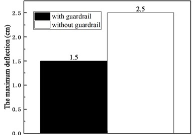
Fig. 4The maximum bending moment with and without guardrails
4.3. The mechanical properties of hinge joints with and without guardrails
The variation law of hinge joint shear force with guardrail and without guardrail were analyzed at first (see Fig. 5).
Fig. 5The mechanical behavior of hinge joints with and without guardrails
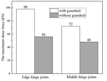
Finite element analysis showed that: The maximum shear force of the edge hinge joint increased by 75 %, and the maximum shear force of the middle joint increased by 50 % when considering the guardrail. Therefore, the mechanical behavior of the hinge joint changes significantly after considering the stiffness of the guardrail. This was because the internal forces of the structure had been redistributed.
In addition, results showed that the contribution of guardrail stiffness had a greater impact on the edge hinge joint than on the middle hinge joint.
Above all, the guardrails has a significant impact on the stress of the hinge joints of pre-stressed hollow slab bridges, and its influence on the edge joints is greater than that on the middle joints.
In addition, the pressure on the contact surface were different between the situations with and without guardrails. So, μN in Eq. (2) were different, and the allowable value of shear force also varied.
The verification of the stress on the hinge joint with and without guardrails were conducted with Eq. (2), The results were shown in Table 1.
Table 1The results of hinge joint verification / kN
Location | Condition | Vcd | [V] | meet the requirements or not |
Edge hinge joints | Without guardrails | 72 | 84 | Yes |
With guardrails | 98 | 92 | No | |
Middle hinge joints | Without guardrails | 48 | 52 | Yes |
With guardrails | 56 | 64 | Yes |
Analysis showed that the mechanical properties of the edge hinge joint and the middle hinge joint without guardrails can meet the requirements of the specifications. However, the force on the edge hinge joint with guardrails increased significantly, which cannot meet the requirements of the specifications and was prone to damage.
Therefore, the calculation result of hinge joint bearing capacity may change from meeting the requirements to not meeting the requirements after considering the impact of guardrails. The guardrails should be considered during the finite element modeling of such bridges in the preliminary design stage.
4.4. The influence of guardrail height on the mechanical properties of hinge joints
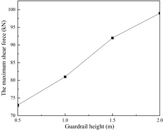
To analyze the influence of guardrail height on the mechanical behavior of hinge joints, different guardrail models (guardrail height: 0.5 m, 1 m, 1.5 m, 2 m) were established, and the maximum shear force of hinge joints under different working conditions was extracted. The research results were shown in Fig. 6.
Research showed that the maximum shear force at mid span increased by 10.96 %, 26 %, and 35.62 %, with the guardrail height increasing from 0.5 m to 1 m, 1.5 m, and 2 m, respectively. The guardrail height has a significant impact on the stress of the hollow slab, and the mid span shear force increases with the increase of guardrail height. It also indicated that the influence of guardrails on the mechanical properties of hinge joints in hollow slab bridges should not be ignored.
Fig. 6The influence of guardrail height on the mechanical behavior of hinge joints
5. Conclusions
The influence of guardrails on the mechanical properties of cast-in-place joints was analyzed based on the airport 1# bridge, and the following results were obtained.
1) The maximum deflection of the structure decreases by 40 %, and the maximum bending moment internal force decreases by 14.5 % after taking into account the guardrail in FEM.
2) The maximum shear force of the hollow slab edge hinge joint increases by 75 %, and the maximum shear force of the middle joint increases by 50 % after taking into account the guardrail in FEM.
3) The maximum shear force at mid span increased by 10.96 %, 26 %, and 35.62 %, with the guardrail height increasing from 0.5 m to 1 m, 1.5 m, and 2 m, respectively.
4) For the overall structural verification, neglecting the stiffness of the guardrail is safe. However, the calculation result of hinge joint bearing capacity may change from meeting the requirements to not meeting the requirements after considering the impact of guardrails. The guardrails should be considered during the finite element modeling of such bridges in the preliminary design stage.
References
-
Q. Zhou, P. C. Feng, and J. T. Zhou, “Temperature field of concrete-filled steel tubular arch bridges and its application,” Advances in Civil Engineering, Vol. 9, No. 9, pp. 1–18, 2022.
-
N. J. Abbas and A. A. Ali, “Prediction of axial capacity of octagonal concrete-filled steel tube columns considering confinement effect,” International Journal of Structural Engineering, Vol. 12, No. 2, pp. 170–175, 2022.
-
P. Achuthan et al., “Axial compression performance of concrete-filled steel tubular columns with different D/t ratios,” Advances in Materials Science and Engineering, Vol. 6, No. 12, pp. 1–13, 2022.
-
Q. Zhou et al., “Full scale experimental study on temperature field of large diameter CFST arch bridges under strong radiation and large daily ambient temperature difference,” Journal of Civil Structural Health Monitoring, Vol. 12, No. 5, pp. 1247–1263, 2022.
-
“General Code for Design of Highway Bridges and Culverts,” JTG D60-2015, China Communications Highway Planning and Design Institute, People’s Communications Press, Beijing, 2014.
-
W. B. Peng et al., “Study on the influence of cast-in-place concrete guardrails on the stress performance of hollow slab edge hinge joints,” Bridge Construction, Vol. 52, No. 4, pp. 39–45, 2022.
-
J. S. Tong, Z. Y. Lin, and Q. Zhou, “Local stability of concrete arch bridge based on Ritz method,” Journal of Computational Methods in Sciences and Engineering, Vol. 1, No. 22, pp. 279–294, 2022.
About this article
The authors have not disclosed any funding.
The datasets generated during and/or analyzed during the current study are available from the corresponding author on reasonable request.
The authors declare that they have no conflict of interest.

