Abstract
The face grinding process depends on high-precision rotary table spindle with a large axial load capacity. This paper develops an ultra-precision rotary table spindle with externally pressurized air bearings consisting of a double-pad thrust bearing and a journal bearing; a vacuum clamp system is designed to locate and hold the workpiece. The dynamic model for the rotor-bearing system has been established by using the Reynolds equation and the rigid-body dynamic theory considering five degrees of freedom (DOF). The effects of static and dynamic behaviors of the spindle with the bearing’s key parameters are analyzed systematically. Finally, an experiment study is conducted to verify the theoretical model.
1. Introduction
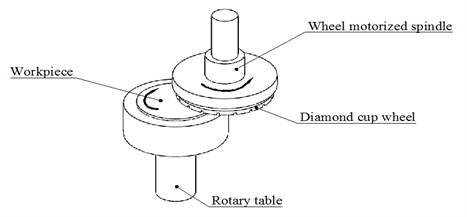
The ultra-precise face grinding is a widely-used processing method in mechanical industry. Fig. 1 shows the schematic view of the face grinding process, the workpiece is held by the porous ceramic vacuum chuck and driven by the rotary table spindle; the diamond cup grinding wheel is driven by the inverted motorized spindle. During grinding process, the grinding wheel and the workpiece rotate around their rotational axes simultaneously [1-3]. Compared with the wheel motorized spindle, the rotary table spindle has a strict technical requirement including a larger axial load capacity and a more complex configuration.
Fig. 1Illustration of face grinding by diamond cup grinding wheel
The rotary table spindle usually consists of a rotor supported by bearing, a motor, a workpiece chuck, a coolant system, an electronic control and measurement system, etc. According to type of bearing, the rotary table spindle can be classified into three categories: the spindle with rolling bearing, the spindle with fluid bearing and the spindle with air bearing. The rolling bearing spindle [4-6] is simple in structure, easy for maintenance, but low in rotation accuracy, limited in working life and moderate in loading capacity. Compared with the rolling bearing spindle, the fluid spindle [7, 8] has higher loading capacity, higher rotation accuracy and longer working life, but more complicated construction and higher manufacture cost. Among three rotary tables, the air bearing spindle [9-11] is highest in the rotation accuracy, lowest in friction loss, lowest in heat generation and longest in working life. Despite of being less favorable in loading capacity, the air bearing spindle can also be used to carry a large load by increasing the diameter and decreasing the clearance of the bearing. Based on the assessment of three types of bearing, the air bearing is preferred to meet the requirement of the ultra-precise face grinding.
This study develops the rotary table spindle with externally pressurized air bearings for the ultra-precise face grinding process. To increase the axial loading capacity, a thrust plate with a large effective area is employed to support the rotor, while, a short radial bearing is used as the radial locating of the spindle’s rotor. A vacuum clamp system is developed to locate and clamp the work piece. The static Reynolds equations and the finite element method are used to analyze the static performances of the rotary table spindle. The perturbation equations and the equations of motion for the rotor-bearing system considering 5 degrees of freedom (DOF) are employed to analyze the dynamic performance of the spindle. Finally, an experiment study is conducted to verify the theoretical model for the rotary table spindle.
2. The rotary table spindle
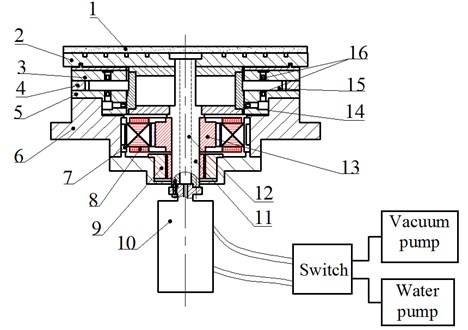
Fig. 2 is the schematic view of the rotary table spindle with externally pressurized air bearings. The workpiece is located on the porous chuck (1), which is mounted on the table (2) and connected with the rotor (11). The rotor (11) is a step-shaped hollow shaft supported by a journal bearing with a short length and a double-pad thrust bearing with a large effective area. The bearing bush (5) consists of the lower pad thrust bearing and the journal bearing. The journal bearing has one row of the orifice restrictors (14) uniformly distributed along circumference to supply compressed air to the bearing clearance, and each pad of the thrust bearing has one row of orifice restrictors (16). A framed DC brushless type motor, including the motor stator (8) and the motor rotor (13), is controlled by the revolver (9) to drive the rotary table spindle; this motor has high power density, low temperature rises and good speed regulation performance. The cooling water jacket (7) is installed outside of the motor stator (8) to take away heat generated by the rotor.
A vacuum clamp system is specially designed to locate and clamp the work piece. The vacuum pump is to pump out the air in the center hole (12), so that the work piece can be located on the porous chuck (1) and clamped by the atmospheric pressure. A water pump is used to pour water into the center hole (12) and then flow through the porous chuck (1) for cleaning the vacuum clamp system. A rotary joint (10) is used to connect the rotor (11) with two pumps and controlled by a switch.
Fig. 2Schematic view of the rotary table spindle: 1 – porous chuck, 2 – table, 3 –upper pad of the thrust bearing, 4 – regulating plate, 5 – bearing bush, 6 – housing, 7 – cooling water jacket, 8 – motor stator, 9 – revolver, 10 – rotary joint, 11 – rotor, 12 – center hole, 13 – motor rotor, 14 – orifice restrictor of journal bearing, 15 – thrust plate, 16 – orifice restrictor of thrust bearing
3. Analysis method
3.1. Bearing modeling
The dynamic analysis of the rotary table is conducted based on the lubrication theory and the rotor dynamic theory. The Reynolds equations for the journal bearing and the thrust bearing are respectively given as [12, 13]:
where R is the radius of the journal bearing, h is the gas film thickness, μ is the dynamic viscosity of air, and ω is the angular velocity of rotor.
The static Reynolds equation and the perturbation equations are obtained by the perturbation method [13-19] and solved by the finite difference method [20-22]. Taking the thrust bearing as an example, the nondimensional static Reynolds equation can be written as:
where ˉr=r/r0 and r0 is the radius at the restrictor position, ˉh=h/c0, h is the film thickness and c0 is the bearing clearance, ˉz=Δz/c0 and Δz is the displacement of the thrust pad, Λ=6μωr2/pac20 is the bearing number, μ is the dynamic viscosity of the air, ω is the angular velocity of rotor and pa is the atmospheric pressure.
Fig. 3Meshes of the gas film
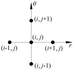
The gas film is meshed by the finite difference method, as shown in Fig. 3. The pressure of node (l, k) can be approximated with the following difference equations:
where, ξ=r, θ, f=p2. Then, the pressure of node (l, k) can be written as:
where, the coefficients of A, B, C, D, E and F are:
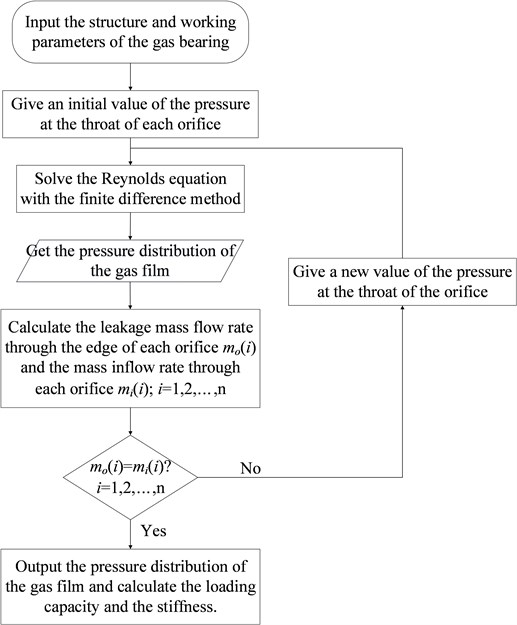
Using Eq. (5), the static Reynolds equation can be approximated as a nonlinear equation, which can be solved by the Newton iteration method. Fig. 4 shows the flow chart to solve the static Reynolds equation.
Fig. 4The flow chart of solving the Reynolds equation
3.2. Spindle dynamic model
Fig. 5 shows the dynamic model of the rotary table spindle. To simplify modeling, the following assumptions are introduced:
1) The journal bearing and thrust bearing are simplified as springs and dampers with linear stiffness coefficients and damping coefficients;
2) The rotor of the rotary table is a rigid body, and the unbalance of the rotor is in the cross-section passing the mass center.
Fig. 5The dynamic model of the rotary table
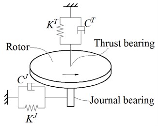
Thus, the motion equations for the rotary table spindle are as follows [14]:
where, m is the mass of the rotor, k is the stiffness of the air bearing and c is the damping of the air bearing, the superscript J is for journal bearing and T is for thrust bearing.
To solve the motion Eq. (6), Laplace transform is employed, thus, Eq. (6) can be written in matrix form:
where, the coefficient matrixes are:
Introducing the following parameters:
A=[OI-M-1K-M-1C],B=[OM-1],D=[IO].
The state equations of the rotary table spindle can be obtained:
where, O is a five-order null matrix, I is a five-order unit matrix, and Y is the output.
For the original state of the rotary table spindle, assuming X2(t=0)=X0, after Laplace transform, the state equations can be written as:
When X0= 0, the transfer function of the spindle can be obtained:
where, G(s) is the transfer function, F(s) is the input and Y(s) is the output. When X(0)≠ 0, the output of the spindle is Y0=D(sI-A)-1X0. When the inputs are the unbalanced force and the grinding force respectively, the outputs are the unbalance response and the force response of the spindle under the grinding force.
4. Static behavior of the air bearing
The specifications of the ultra-precision rotary table motorized spindle are listed in Table 1, and the structural and running parameters of the air bearings used are listed in Table 2.
Table 1The specifications of the rotary table spindle
Items | Values |
Axial stiffness [N/μm] | 1000 |
Radial stiffness [N/μm] | 100 |
Axial load capacity [N] | 3000 |
Table 2Structure and running parameters of the air bearings
Journal bearing | Thrust bearing | ||
Items | Values | Items | Values |
Radius [mm] | 85 | Outer radius of the thrust bearing [mm] | 140 |
Length [mm] | 28 | Inner radius of the thrust Bearing [mm] | 85 |
Row of the restrictor | 1 | Row of the restrictor | 1 |
Clearance [μm] | Undefined | Clearance [μm] | Undefined |
Number of the restrictor | Undefined | Number of restrictors | Undefined |
Inner diameter of the restrictor [mm] | 0.2 | Inner diameter of the restrictor [mm] | 0.2 |
Supplied pressure of air [MPa] | 0.6 | Supplied pressure of air [MPa] | 0.6 |
Ambient pressure [MPa] | 0.1 | Ambient pressure [MPa] | 0.1 |
Dynamic viscosity of the air [Ns/m2] | 18.4×10⁻⁶ | Dynamic viscosity of the air [Ns/m2] | 18.4×10⁻⁶ |
Considering the performance of the rotary table spindle is mainly influenced by the static and dynamic characteristics of the air bearings, the variations of axial load capacity, axial stiffness and radial stiffness of the table with the number of the restrictors and the bearing clearance are discussed in this section.
4.1. Axial load capacity
Fig. 6 shows the variation of the axial load capacity with the bearing clearance and the number of restrictors. In this section, the axial load capacity is obtained with the eccentricity ratio ε= 0.3. It can be seen from Fig. 6 that for any given number of restrictors, there is an optimum clearance so that the bearing has the maximum axial load capacity, and this optimum clearance increases with the number of restrictors.
4.2. Axial stiffness
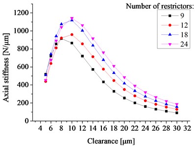
Fig. 7 shows the variation of the axial static stiffness with the bearing clearance and the number of the orifice restrictors. The results show that the trend of axial static stiffness is similar with the axial load capacity. When the number of restrictor remains constant, there is an optimum clearance such that the bearing has the maximum axial stiffness, and this optimum clearance increases with the number of orifice restrictors.
Fig. 6The axial loading capacity vs. the bearing clearance and the number of restrictors
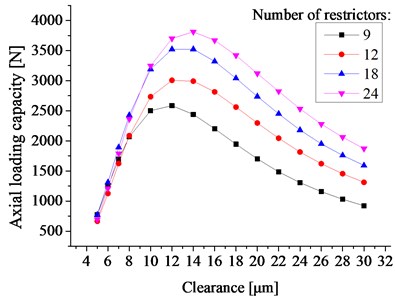
Fig. 7The axial stiffness vs. the bearing clearance and the number of restrictors
4.3. Radial stiffness
Fig. 8 shows the static radial stiffness with the clearance ranging from 10 μm to 30 μm. To simplify the manufacture of the orifice restrictors, the inner diameter of the restrictor used in the journal is equal to the thrust bearing. The results show that the radial static stiffness will reach a maximum value of 107.89 N/μm when the clearance is 12 μm.
It should be mentioned that the radial stiffness of the spindle is less than the axial stiffness; this can be attributed to the fact that a short radial journal bearing employed decrease the radial stiffness. Since the spindle is used to carry out the axial load mainly, the short radial journal bearing is served as a radial locating element for the spindle. It is rather intuitive that the shorter the radial journal bearing, the smaller the perpendicularity between the thrust plate and the radial journal bearing. Thus, the double-pad thrust bearing with large effective area employed in the spindle can carry out the large axial external load, meanwhile, the journal bearing with short length used decrease the spindle manufacturing cost greatly.
Based on the above analysis, the appropriate parameters for the journal bearing and the thrust bearing are list in Table 3.
Table 3The structure parameters of the air bearings
Journal bearing | Thrust bearing | ||
Items | Values | Items | Values |
Clearance [μm] | 12 | Clearance [μm] | 12 |
Number of the restrictor | 24 | Number of restrictors | 24 |
Fig. 8The radial stiffness vs. the bearing clearance and the number of restrictors
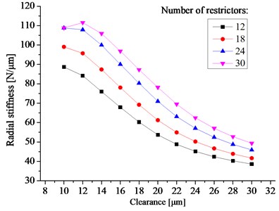
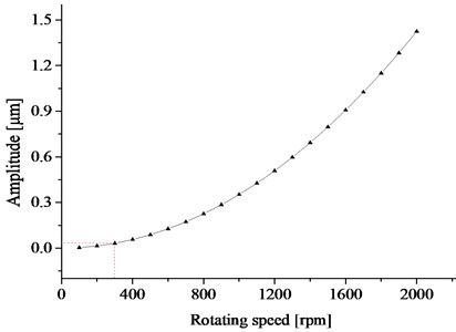
Fig. 9Unbalance response of the rotor
5. Unbalance response of the rotary table spindle
The structure and running parameters are as follows:
(1) The mass of the rotor is m=27.42 kg, and the moments of inertia are Jp=1.253 kgm2 and Jd=0.6472 kgm2;
(2) The running speed of the table is 300 rpm;
(3) The grade of the balance quality of the rotor is G2.5, so that the eccentricity is about 83.3 μm.
Fig. 9 shows the unbalanced response of the rotary table spindle within the rotational speed of 500 rpm, and the vibration amplitude is about 31.6 nm at 300 rpm, which is less than the allowed rotation error of 50 nm.
6. Forced response of the rotary table spindle
The analysis method of forced response of the rotary table spindle under grinding force refers to [14]. Table 4 shows the maximum values of the displacement and tilt angle of the rotary table spindle under the grinding force. The maximum displacements of the rotor in x, y and z directions are 0.1653 μm, 0.1649 μm and 0.271 μm respectively. It should be noted that the displacements of the rotor are much smaller than the clearance of the air bearings.
Table 4Forced response of the motorized spindle
Items | Values |
Maximum displacement in x direction [m] | 1.653×10⁻⁷ |
Maximum displacement in y direction [m] | 1.649×10⁻⁷ |
Maximum displacement in z direction [m] | 2.710×10⁻⁷ |
7. Experiment
Fig. 10 shows the experimental system for measuring the axial static stiffness of the rotary table. The rotary Table (3) is mounted on the test stand (4). The spring-loaded method [14] consists of the upper load-applying block (6), the lower load-applying block (9), the load-applying bolt (1), the guide bar (2), and the spring (7). The test force F is measured by the force sensor (8), and the axial displacement Δz of spindle top due to the air film deformation is measured by the micrometer (5). Therefore, the axial static stiffness can be calculated by kz=F/Δz. The relationship of the axial displacement of the spindle top with the applied force in axial direction is list in Table 5, the result shows that the test value of the axial static stiffness of the rotary table is about 950 N/μm, which is close to the theoretical value 1000 N/μm.
Table 5The relationship of the air film deformation with the applied force in axial direction
Axial applied force F, N | Air film displacement Δz, μm |
1000 | 2.5-2.6 |
2000 | 3.6-3.7 |
3000 | 4.6-4.8 |
The unbalance response of the rotary table spindle was measured by a capacitance micro-displacement sensor with a detectable minimum value of 100 nm, and the signal is sampled and analyzed by the Spindle Error Analyzer from Lion Precision in American. However, when the spindle reaches the running speed of 300 rpm, the amplitude of the unbalance response is too small to be detected, indicating that the unbalance response of the spindle is less than 100 nm.
Fig. 10Test rig for measuring the axial stiffness of the spindle (1 – load-applying bolt, 2 – guide bar, 3 – rotary table, 4 – test stand, 5 – micrometer, 6 – upper load-applying block, 7 – spring, 8 – force sensor, 9 – lower load-applying block)
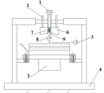
a) Schematic diagram
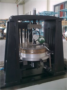
b) Photograph
8. Conclusions
An ultra-precision rotary table spindle for the face grinding process has been developed, including an externally pressurized air axial bearing with a large diameter to carry the axial load, an externally pressurized air radial bearing with a short length to serve as a radial locating surface, a vacuum clamp system to locate and clamp the work piece, a framed DC brushless type motor to drive the spindle. This support can not only meet the demand of the face grinding, but also reduce the manufacturing cost of the spindle greatly.
Reynolds equations for the journal bearing and the thrust bearing are used to model the air bearing, and the static Reynolds equation and the perturbation equations are obtained by the perturbation method and solved by the finite difference method. The rotor dynamic model for the spindle is established by the rigid-body dynamic theory to predict the dynamic response.
For the air bearing of the rotary table spindle, there exists an optimum clearance for a given number of restrictors such that the table has the maximum axial loading capacity, maximum axial stiffness, and the optimum clearance increases with the number of restrictor. The axial load capacity of the rotary table spindle can be greatly increased by increasing the effective area and decreasing the clearance of the thrust bearing. The dynamic analysis results under cutting force show that the developed rotary table spindle has a vibration displacement amplitude of 0.1-0.3 μm, indicating that the spindle can be used for high-precision face grinding.
References
-
Pei Z. J. A study on surface grinding of 300 mm silicon wafers. International Journal of Machine Tools and Manufacture, Vol. 42, Issue 1, 2002, p. 385-393.
-
Lin B., Li Z., Sun W., Zhang X. An overview of current research on simultaneous double side grinding of silicon wafers. ECS Transactions, Vol. 27, Issue 1, 2010, p. 1087-1092.
-
Huo F. W., Guo D. M., Feng G., Kang R. K., Wang R. L. A new kinematics for ultra-precision grinding of conical surfaces using a rotary table and a cup wheel. International Journal of Machine Tools and Manufacture, Vol. 59, 2012, p. 34-45.
-
Jovanovic J. D., Tomovic R. N. Analysis of dynamic behavior of rotor-bearing system. Proceedings of the Institution of Mechanical Engineers Part C – Journal of Mechanical Engineering Science, Vol. 228, Issue 12, 2014, p. 2141-2161.
-
Rahman A. K., Aini R., Gohar R. On the performance of multi-support spindle-bearing assemblies. Proceedings of the Institution of Mechanical Engineers Part K – Journal of Multi-Body Dynamics, Vol. 216, Issue 2, 2002, p. 117-132.
-
Karacay T., Akturk N. Vibrations of a grinding spindle supported by angular contact ball bearings. Proceedings of the Institution of Mechanical Engineers Part K – Journal of Multi-Body Dynamics, Vol. 222, Issue 1, 2008, p. 61-75.
-
Chen W., Sun Y., Liang Y., Bai Q., Zhang P., Liu H. Hydrostatic spindle dynamic design system and its verification. Proceedings of the Institution of Mechanical Engineers Part B-Journal of Engineering Manufacture, Vol. 228, Issue 1, 2014, p. 149-155.
-
Montusiewicz J., Osyczka A. Computer aided optimum design of machine tool spindle systems with hydrostatic bearings. Proceedings of the Institution of Mechanical Engineers Part B-Journal of Engineering Manufacture, Vol. 211, Issue 1, 1997, p. 43-51.
-
Akhondzadeh M., Vahdati M. An experiment on the shape and depth of air pocket on air spindle vibrations in ultra-precision machine tools. Proceedings of the Institution of Mechanical Engineers Part B-Journal of Engineering Manufacture, Vol. 227, Issue B4, 2013, p. 616-620.
-
Lee D. G., Choi J. K. Design and manufacture of an aerostatic spindle bearing system with carbon fiber-epoxy composites. Journal of Composite Materials, Vol. 34, Issue 14, 2000, p. 1150-1175.
-
Wu D., Wang B., Luo X., Qiao Z. Design and analysis of aerostatic spindle with high load characteristics for large ultra-precision drum lathe. Proceedings of the Institution of Mechanical Engineers, Part J: Journal of Engineering Tribology, 2015.
-
Constantinescu V. N. Gas Lubrication. 1969.
-
Jang G. H., Kim Y. J. Calculation of dynamic coefficients in a hydrodynamic bearing considering five degrees of freedom for a general rotor-bearing system. ASME Journal of Tribology, Vol. 121, Issue 3, 1999, p. 499-505.
-
Xu C., Jiang S. Dynamic analysis of a motorized spindle with externally pressurized air bearings. ASME Journal of Vibration and Acoustics, Vol. 137, Issue 4, 2015, p. 041001.
-
Klit P., Lund J. W. Calculation of the dynamic coefficients of a journal bearing, using a variational approach. ASME Journal of Tribology, Vol. 108, Issue 3, 1986, p. 421-425.
-
Lund J. W. Review of the concept of dynamic coefficients for fluid film journal bearings. ASME Journal of Tribology, Vol. 109, Issue 1, 1987, p. 37-41.
-
Kim M., Jang G., Kim H. Stability analysis of a disk-spindle system supported by coupled journal and thrust bearings considering five degrees of freedom. Tribology International, Vol. 43, Issue 8, 2010, p. 1479-1490.
-
Lund J. W., Pedersen L. B. The influence of pad flexibility on the dynamic coefficients of a tilting pad journal bearing. ASME Journal of Tribology, Vol. 109, Issue 1, 1987, p. 65-70.
-
Oh S. M., Rhim Y. C. The numerical analysis of spindle motor bearing composed of herringbone groove journal and spiral groove thrust bearing. KSTLE International Journal, Vol. 2, Issue 2, 2001, p. 93-102.
-
Belforte G., Colombo F., Raparelli T., Trivella A., Viktorov V. High-speed electrospindle running on air bearings: design and experimental verification. Meccanica, Vol. 43, Issue 6, 2008, p. 591-600.
-
Yang P., Zhu K., Wang X. On the Non-linear stability of self-acting gas journal bearings. Tribology International, Vol. 42, Issue 1, 2009, p. 71-76.
-
Lo C. Y., Wang C. C., Lee Y. H. Performance analysis of high-speed spindle aerostatic bearings. Tribology International, Vol. 38, Issue 1, 2005, p. 5-14.
About this article
This study was funded by the National Science Foundation of China (Grant Numbers 51635004 and 11472078) and the Jiangsu University-Industry Collaboration Project (Grant Number BY2015070-26).

