Abstract
This paper investigates the translational oscillatory motion of a single-degree-of-freedom thin plate under variable airflow conditions, including wind gusts, harmonic flow, and airflow with random parameters. The proposed airflow device is designed as a swing pendulum, where the plate is connected to a fixed base by two identical cranks, with a power generator attached to the end of one crank axle. The rotary motion of the cranks due to airflow is evaluated using an energy dissipation parameter. The interaction between the airflow and the plate undergoing translational (i.e., non-rotational) motion is studied numerically through computer simulations, applying the principle of superposition. In this approach, the fast chaotic motion of air particles (Brownian motion) is separated from the slower flow motion. The modeling incorporates the concept of pressure (downwind) and suction (upwind) zones for a rigid body immersed in an airflow. The analytical formulas derived from these calculations are then used to analyze the motion of the electromechanical system. System parameters are optimized, using generated power as the evaluation criterion. Numerical results confirm the feasibility and efficiency of the proposed wind energy system under non-stationary airflow conditions. The device is suitable for installation in open fields, on building rooftops, along highways, or in tunnels. It is environmentally friendly and poses no harm to people.
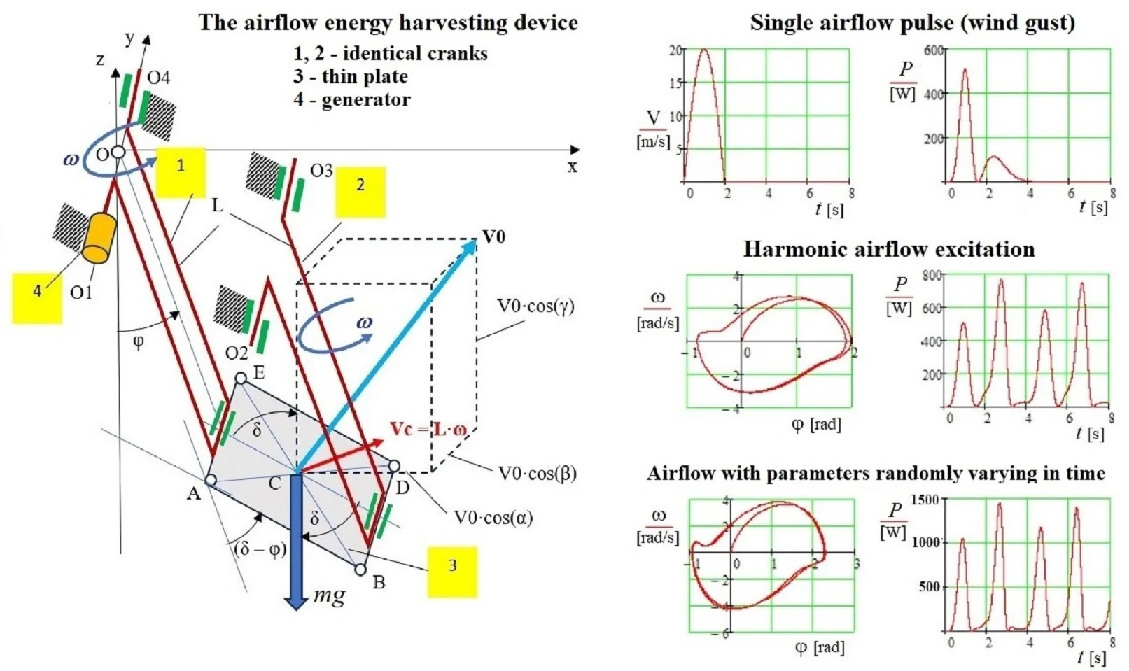
Highlights
- A new airflow energy harvesting device, designed as a swing pendulum, is proposed and validated through computer simulation under non-stationary airflow conditions (gusts, harmonic flow, random airflow).
- Flat plate oscillatory motion in a variable air flow is studied using the approximate analytical method for space-time analysis based on the concept of pressure and suction zones around a rigid body in an airflow.
- The efficiency of the proposed device is confirmed by computer modeling and estimated by the maximum output power, which ranges from 600 W to 1500 W.
- The proposed device can be used to harness power from a non-stationary airflow in open spaces, as well as in tunnels, along highways, and other areas where airflow is due to heavy traffic.
1. Introduction
Wind energy is now a key source of renewable power, driving the development of large wind farms and gaining popularity in residential, small business, and agricultural applications for decentralized energy production. Large turbines convert airflow into mechanical energy through radial blades on a central rotor [1]. Small turbine designs vary, making the optimization of energy capture essential for efficiency [2]-[5]. However, in both large and medium-sized turbines, high tip velocities lead to noise, vibrations, and stress at attachment points, often causing damage [6]. Small systems that harness variable wind-induced vibrations have also been developed [7]-[9].
A review of existing research shows that analyzing airflow dynamics with moving objects involves complex, large-scale computations. To simplify this, an approximate analytical method has been introduced to study interactions between airflow and moving flat blades [10]. This method enables the synthesis and optimization of airflow energy conversion systems without requiring complex space-time programming procedures [11], [12]. The present study investigates the use of a two-crank and flat-plate design of airflow device with non-periodic oscillations to generate power from unsteady flow, applying the previously mentioned approximate theory [10].
2. Description of the model of air flow energy harvesting equipment
The air flow energy harvesting device is designed as a swing pendulum (Fig. 1) consisting of two identical cranks 1 and 2, connected to a thin rectangular ABDE plate 3. The cranks rotate around parallel axes O1-O4 and O2-O3. Since both cranks have the same length L and remain parallel, the plate 3 moves translationally, with all points sharing the same velocity Vc=Lω, where ω is the angular velocity of the cranks and Vc is the velocity of the plate’s center C. An air flow of variable modulus V0 and direction acts on the plate, whose orientation in the fixed reference system Oxyz is defined by the angles α, β, γ.
Here, the Oz axis is vertical, parallel to the gravitational force mg. The inclination of plate 3 at an angle δ from the vertical is determined by the fact that the axis O2-O3 is either lower or higher than the axis O1-O4. This mechanical system has one degree of freedom, described by the angle φ. Air flow energy is harvested by a generator 4 located at the end of crank 1. To analyze dynamics of the proposed structure, the differential equation of motion for the angle φ must be formulated. In deriving this differential equation, the approximate space-time analysis method [10]-[12] is beneficial. The application of this method to describe the motion is discussed in the next section.
Fig. 1The air flow energy harvesting device: Oxyz – inertial coordinate system; 1 – cranc with generator; 2 – second cranc; 3 – flat plate; 4 – generator; V0 – air flow velocity; L – length of crank arms; Vc – plate centre velocity; ω – angular velocity of cranks
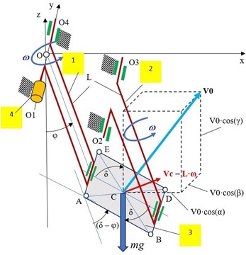
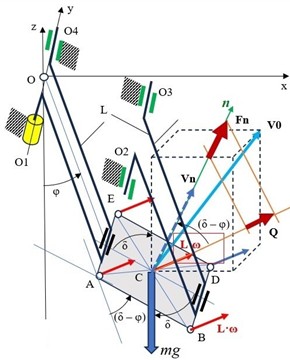
Fig. 2Airflow and plate interaction forces: n – plate normal; Vn and Fn – relative velocity and interaction force, respectively, in the direction of the normal n; Q – the component of the force Fn, that is parallel to the velocity Vc of the center C
3. Equation of motion of an electromechanical system
For the considered system with one degree of freedom (coordinate φ, Figs. 1-2), the differential equation of motion can be derived using the theorem on the change of kinetic energy [13]:
where T is a kinetic energy, Pw is a power of air flow and plate interactions, PG is a power of direct current generator, Pmg is a power of gravity forces, PR is a power of resistance forces.
Separate components of Eq. (1) can be presented in the following form:
where Q is the component of the interaction force Fn between the air flow and the plate along the velocity Vc (Fig. 2), L is the length of the crank arm, ˙φ is the angular velocity of the crank, and C0, C1 are constants used in the generator power calculations [14]. Other parameters include: mp – mass of the plate, mc – mass of one crank, Lc – the radial coordinate of the crank’s center of mass. Constants C2, C3 and C4 correspond to the square, dry and linear friction forces, respectively. JpCy represents the moment of inertia of the plate about the center axis Cy, while JcOy and JGOy represent the moments of inertia of the crank and generator masses about the axis of rotation Oy.
The components Q of the interaction normal force Fn are determined as follows [10]-[12]. First, the projection Vn of the relative velocity between the fluid flow V0 and the plate velocity Vc=L˙φ onto the plate normal n is calculated (Fig. 2):
=V0∙[cos(α)∙cos(δ)+cos(γ)∙sin(δ)]-L∙˙φ∙cos(˙δ-φ).
Next, the forces Fn acting along the normal are determined as a function of the square of the relative normal velocity Vn:
where C= (0.25-0.5) is a constant [10], ρ is an air density, A is an area of plate, sign(Vn)=±1.
Afterward, the component Q is calculated (Fig. 2), as shown here:
Using Eqs. (1-9), the following differential equation of motion for the plate is derived:
Using Eq. (10), various problems related to the analysis and optimization of the described system under variable airflow conditions can be solved. Some of them are discussed below.
4. Analysis of free oscillations of the plate
Under real conditions, free oscillations of the plate can occur due to the impact of individual airflow pulses, such as wind gusts. The motion of the plate is analyzed from rest (φ=0, ˙φ = 0) assuming a single pulse action along the Ox axis, as described by the following equation:
The results of the numerical modeling are shown in Figs. 3-6, with the following system and excitation parameters: JpCy+2·JcOy+JGOy= 12.167 kg·m2; C= 0.5; ρ= 1.25 kg·m-3; A= 1 m2; L= 1 m; LC= 0.5 m; mp= 10 kg; mc= 0.2 kg; v0= 20 m·s-1; α= 0 rad; β=π2-1 rad; γ= π·2-1 rad; δ= 0,707 rad; C0= 0; C1= –80 kg·m2·s-2·rad-1; C2= 0; C3= 0; C4= 0; p= 1.6 rad·s-1.
Fig. 3Single air flow pulse with a duration t= 2 s and a maximum velocity of v0= 20 m·s-1
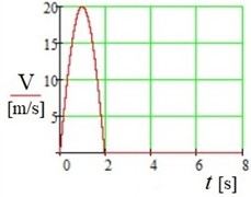
Fig. 4Total angular velocity ω of the cranks and generator as a function of the angle φ
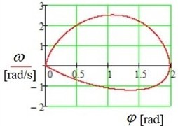
Fig. 5The moment M generated by the air flow as a function of time t, with the plates in a back-and-forth oscillating motion
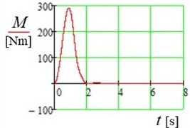
Fig. 6The resulting generated power P as a function of time t (Pmax= 508 W)
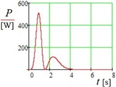
The following conclusions can be drawn from the modeling results (Figs. 3-6):
1) The developed methodology enables the modeling of plate oscillations in a varying airflow.
2) The developed model allows determining the power generated by the air flow, the maximum value of which is large enough for a plate area of one square meter, i.e. about 500 W.
3) The single air pulse interaction model demonstrates that the proposed theory can be applied to the analysis of various types of air flow-plate interactions.
Some examples of stationary motion are discussed here below.
5. Harmonic air flow effect analysis
Harmonic airflow excitation is described by the following equation:
Computer simulation results for the case of harmonic airflow excitation in accordance with Eq. (12) are presented in Figs. 7-8. The modeling results lead to the following conclusions:
1) The periodic movement of the system occurred rapidly, appearing within the first oscillation cycle (Fig. 7).
2) Periodic oscillations occur with asymmetric “fluttering” within the range of −1 rad ≤φ≤2 rad.
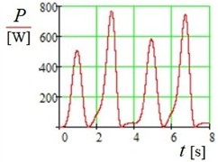
The power output (Fig. 8), with a peak value of approximately 770 W, confirms that the proposed device can efficiently harvest energy from stationary (harmonic) air flow.
Fig. 7Motion in phase plane (φ, ω)
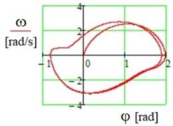
Fig. 8Change in generated power P over time t (Pmax= 770 W)
6. Analysis of the effect of air flow with parameters randomly varying in time
To evaluate the performance of the device and confirm the effectiveness of the calculation method, the action of air flow with a random amplitude and frequency was additionally analyzed:
For the previously used system parameters (see section 4), examples of computer simulation results for the random airflow Eq. (13) are presented in Figs. 9-10.
The following conclusions can be drawn from the computer modeling results:
1) The proposed design for energy extraction from air flow is capable to operate under excitations with random parameters.
2) The quasi-periodic movement of the system occurred rapidly, appearing within the first oscillation cycle (Fig. 9).
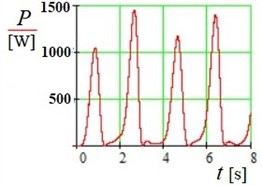
3) The modeling results confirm that the device operates more efficiently with varying random air flows than with stationary harmonic ones (compare Fig. 8 and Fig. 10).
Fig. 9Motion in phase plane (φ, ω)
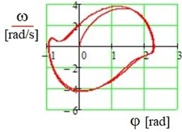
Fig. 10Change in generated power P over time t (Pmax=1456 W)
7. Conclusions
1) The novelty of this study lies in applying an approximate analytical method for space-time analysis to investigate the interaction between airflow and a moving plate, determining the plate’s motion. Developed by the authors [10], [12], this approach uses the concept of pressure and suction zones around a rigid body in airflow. The interaction is described by changes in momentum in differential form, and dynamic analysis is conducted via the numerical solution of a simplified second-order differential equation with constant parameters, avoiding complex space-time programming.
2) The applicability of the proposed method for analyzing airflow-rigid body interactions is confirmed by experiments involving thin plates and physical models of airflow devices conducted in the Armstrong Subsonic wind tunnel (the results of these experiments are detailed in [12]).
3) A new airflow energy harvesting device, designed as a swing pendulum, is proposed and validated through computer modeling under non-stationary airflow conditions (gusts, harmonic flow, random airflow). Its efficiency, based on maximum power output, ranges from 600 W to 1500 W. Future research will focus on experimental validation using a device prototype.
4) The proposed device can be used to harness power from a non-stationary airflow in open spaces, as well as in tunnels, along highways, and other areas where airflow is due to heavy traffic.
References
-
H. Canet, P. Bortolotti, and C. L. Bottasso, “On the scaling of wind turbine rotors,” Wind Energy Science, Vol. 6, No. 3, pp. 601–626, May 2021, https://doi.org/10.5194/wes-6-601-2021
-
D. Le Gourieres, Wind Power Plants. Theory and Design. Oxford, UK: Pergamon Press, 1982.
-
J. F. Manwell, J. G. Mcgowan, and A. L. Rogers, Wind Energy Explained: Theory, Design and Application. Chichester, UK: John Wiley & Sons, 2009.
-
D. A. Umar, C. T. Yaw, S. P. Koh, S. K. Tiong, A. A. Alkahtani, and T. Yusaf, “Design and optimization of a small-scale horizontal axis wind turbine blade for energy harvesting at low wind profile areas,” Energies, Vol. 15, No. 9, p. 3033, Apr. 2022, https://doi.org/10.3390/en15093033
-
S. Khan, “A modeling study focused on improving the aerodynamic performance of a small horizontal axis wind turbine,” Sustainability, Vol. 15, No. 6, p. 5506, Mar. 2023, https://doi.org/10.3390/su15065506
-
D. Liao, S.-P. Zhu, J. A. F. O. Correia, A. M. P. de Jesus, M. Veljkovic, and F. Berto, “Fatigue reliability of wind turbines: historical perspectives, recent developments and future prospects,” Renewable Energy, Vol. 200, pp. 724–742, Nov. 2022, https://doi.org/10.1016/j.renene.2022.09.093
-
Z. Li, Y. Zhang, L. Yang, and H. Chen, “Overview of piezoelectric energy harvester based on wind-induced vibration effect,” Journal of Vibroengineering, Vol. 26, No. 3, pp. 615–628, May 2024, https://doi.org/10.21595/jve.2023.23421
-
A. Abdelkefi, “Aeroelastic energy harvesting: A review,” International Journal of Engineering Science, Vol. 100, pp. 112–135, Mar. 2016, https://doi.org/10.1016/j.ijengsci.2015.10.006
-
A. Nayyar and V. Stoilov, “Power Generation from Airflow Induced Vibrations,” Wind Engineering, Vol. 39, No. 2, pp. 175–182, Apr. 2015, https://doi.org/10.1260/0309-524x.39.2.175
-
J. Viba, V. Beresnevich, and M. Irbe, “Synthesis and optimization of wind energy conversion devices,” in Design Optimization of Wind Energy Conversion Systems with Applications, IntechOpen, 2020, pp. 125–141, https://doi.org/10.5772/intechopen.90819
-
V. Beresnevich et al., “Wind energy conversion generator,” in 20th International Scientific Conference Engineering for Rural Development, Vol. 20, pp. 955–960, May 2021, https://doi.org/10.22616/erdev.2021.20.tf213
-
J. Viba, V. Beresnevich, and M. Irbe, “Methods and devices for wind energy conversion,” in Wind Turbines – Advances and Challenges in Design, Manufacture and Operation, IntechOpen, 2022, pp. 247–270, https://doi.org/10.5772/intechopen.103120
-
J. L. Meriam, L. G. Kraige, and J. N. Bolton, Engineering Mechanics: Dynamics. New York, USA: John Wiley & Sons, 2016.
-
M. Neagoe and R. Saulescu, “Comparative energy performance analysis of four wind turbines with counter-rotating rotors in steady-state regime,” Energy Reports, Vol. 8, pp. 1154–1169, Nov. 2022, https://doi.org/10.1016/j.egyr.2022.07.092
About this article
The authors have not disclosed any funding.
The datasets generated during and/or analyzed during the current study are available from the corresponding author on reasonable request.
The authors declare that they have no conflict of interest.

