Abstract
Grouting reinforcement method is one of the effective methods commonly used in slope reinforcement. At present, grouting reinforcement technology is mostly aimed at sandy soil and clay, and the research on gravel soil is still relatively few. At the same time, because of the strong concealment of slurry diffusion in grouting reinforcement, the process and law of slurry diffusion in grouting process has always been a difficult problem. In this paper, through numerical simulation analysis and indoor simulation grouting test, the law of slurry diffusion flow in slope gravel soil grouting is analyzed, and compared with the law of slurry diffusion in sand. At the same time, the pressure distribution along the slurry diffusion process and the changes of soil parameters before and after grouting are also analyzed. The results show that the final diffusion radius of slurry is proportional to the water-cement ratio and grouting pressure of cement slurry, and the diffusion radius of slurry in slope gravel soil is much larger than that in sand. In slurry diffusion, the pressure along the road gradually attenuates with slurry diffusion, and its attenuation rate is inversely proportional to the water-cement ratio of cement slurry. The attenuation rate in slope gravel soil layer is much slower than that in sand layer. After the slope gravel soil layer and sand soil layer are strengthened by grouting, the porosity of the soil layer decreases and the compressive strength increases. The research results indicate the diffusion law of grouting slurry in slope gravel soil and provide reference for similar engineering designs.
1. Introduction
In recent years, there has been an increasing amount of infrastructure construction in the western region with the implementation of the Western Development Strategy. Due to the unique geological and climatic conditions in the western region, there are a large number of slope soil and gravel soil sections. Slope gravel soil is a heterogeneous mixture of soil and rock, characterized by coarse-grained soil and fine-grained soil. This type of soil is damp, with a high porosity and poor self stability. Grouting reinforcement technology is commonly used to improve the stability of rocks (soils). It is often used to achieve hydraulic sealing, geological reinforcement and water isolation, and improve the bearing capacity of surrounding rock in engineering[1]. At present, the research on grouting reinforcement technology at home and abroad mainly includes theoretical analysis, numerical analysis, model experiments, and other aspects.
The current grouting theories mainly include infiltration grouting theory, splitting grouting theory, and compaction grouting theory. In 1938, Maag[2]derived the theoretical formula for the spherical diffusion of Newtonian fluid slurry in geological formations based on Darcy’s law. Yang et al. [3-4] derived the calculation formula for the effective diffusion radius of Bingham body and power-law fluid slurry during infiltration grouting in sandy soil based on the generalized Darcy's law and spherical diffusion theory model. Yang et al. [5] considered the time-varying viscosity of slurry fluids and established the slurry seepage equation and the theoretical equation for slurry diffusion along a hemisphere based on Darcy’s law.
The commonly used numerical simulation methods in grouting simulation include finite element method, finite difference method and discrete element method, etc. Bouchelaghem et al. [6]established a numerical model for cylindrical grouting simulation of cement-based granular slurry, conducted numerical simulation of infiltration grouting in porous media, and analyzed the fluid mechanics properties and grouting effect of saturated sand slurry. Feng [7] assumed that the injected medium was anisotropic to numerically simulate the diffusion law of the formation slurry during the grouting process. The results showed that the diffusion speed of the slurry varied from fast to slow during the grouting process. Wang [8] used the discrete element program (PFC2D) to study the relationship between grouting pressure and diffusion radius. The results showed that there was a certain error between the numerical simulation results and the actual situation.
Ge [9]conducted indoor simulation experiments to study the influence the structural characteristics of the injected medium, the water cement ratio and properties of the slurry, and the injection pressure made on the injection volume, slurry diffusion radius, and stone strength; Yang et al. [10] conducted grouting experiments on sand and gravel layers, and studied the migration law and grouting mechanism of slurry in sand and gravel layers through a pressure test bench. The diffusion law of slurry in high permeability environments was analyzed based pebble shape and pore size. Lei [11] and Yang et al. [12] achieved some research results in using grouting technology to reinforce gravel soil. Pang and Yao [13]conducted research on the use of ultrafine cement grouting in mining areas where water containing pebble layers were encountered during excavation.
At present, most of the theories on grouting reinforcement at home and abroad assume relatively ideal conditions, which have poor applicability in practical engineering. At the same time, current research on grouting reinforcement technology is mostly focused on the fields of sand and clay. There is relatively little research on grouting reinforcement in the field of slope gravel soil with high stone content, large particle size, loose structure, high porosity, and high permeability. This article studies the diffusion law and reinforcement effect of grouting reinforcement slurry in slope gravel soil, which can provide theoretical reference for practical grouting engineering in slope gravel soil layers.
2. Numerical models and operating condition settings
2.1. Model establishment
Taking a large-scale slope treatment project in southwestern China as the engineering background, the numerical simulation analysis model is as shown in Fig. 1. The model is 12 meters long and 10 meters wide, with a maximum height of 16 meters and a minimum height of 10 meters above. It is divided into three layers. The topmost layer is a slope gravel soil layer, with an upper slope of 1:2 and a thickness of 5-6 meters. The middle layer is a sand soil layer, with an upper slope of about 1:1.7 and a thickness of 2-4 meters. The bottommost layer is bedrock with a thickness of 2-7 meters. According to the engineering design, it’s inserted a grouting steel pipe in the middle of the model, with a horizontal inclination angle of 20 degrees. It’s injected grout through the grouting steel pipe with a diameter of 89 mm, a thickness of 6 mm and a length of 7 m.
2.2. Working condition settings
During the grouting process, the permeability pressure of the grout was used to evaluate the diffusion range of the slurry. To simulate the diffusion process of cement slurry in slope gravel soil under different grouting pressures, this paper used grouting pressures of 0.2 MPa, 0.4 MPa, and 0.6 MPa, and a representative water cement ratio of 1. At the same time, cement slurry with water cement ratios of 0.8 and 0.5 were used as different viscosity slurries for comparison.
The viscosity variability of the slurry was considered in the simulation of grouting process. Firstly, the average viscosity of the slurry was calculated every 60 seconds, and then the viscosity ratio of the slurry to water was obtained. The next time period can be calculated based on the previous time period (60 seconds is a time period). The viscosity of cement slurry was measured using a viscosity meter at different time points for cement slurry with different water cement ratios. The viscosity values and densities at different time points were recorded, and the recorded data were fitted using MATLAB software. Finally, the viscosity time-varying formula of cement slurry with different water cement ratios was obtained. There were three operating conditions for numerical simulation (see Table 1).
Fig. 1Slope model diagram
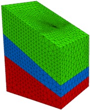
Table 1Operating conditions table
Working conditions | Grouting pressure (MPa) | Water cement ratio | Slurry viscosity (mPa.s) | Slurry density (g/cm3) |
1 | 0.2 | 1.0 | 407.408 | 1.64 |
2 | 0.4 | 1.0 | 407.408 | 1.64 |
3 | 0.6 | 1.0 | 407.408 | 1.64 |
4 | 0.4 | 0.8 | 28.17 | 1.64 |
5 | 0.4 | 0.5 | 15.626 | 1.64 |
2.3. Definition of materials and parameters
The material parameters of soil include elastic modulus, Poisson’s ratio, porosity, cohesion, friction angle, etc.
The elastic modulus of the slope gravel soil layer was defined as 30 MPa, corresponding to 1×10³ MPa for the strongly weathered rock layer and 2.2×10³ MPa for the moderately weathered rock layer.
Poisson’s ratio of the slope gravel soil layer was defined as 0.32, corresponding to 0.27 for the strongly weathered rock layer and 0.23 for the moderately weathered rock layer. The cohesion of the slope gravel soil layer was defined as 6 kPa, with an internal friction angle of 38 degrees.
The cohesion of the strongly weathered rock layer was 15 kPa, with an internal friction angle of 32 degrees. The cohesion of the moderately weathered rock layer was 22 kPa, with an internal friction angle of 28 degrees.
The porosity of the slope gravel soil layer was defined as 0.33, the porosity of the strongly weathered rock layer was 0.29, and the porosity of the moderately weathered rock layer was 0.24. The permeability coefficient of the slope gravel soil layer was defined as 0.65 cm/s.
The Poisson’s ratio of the strongly weathered rock layer was 3×10⁻³cm/s, and the Poisson’s ratio of the moderately weathered rock layer was 1×10⁻⁴ cm/s. However, the permeability coefficient in FLAC 3D differed from that specified in general soil mechanics. The conversion relationship between the permeability coefficient in FLAC 3D software and the permeability coefficient unit in general soil mechanics was as follows:
In this model, permeable boundaries are chosen for both the model boundary and the pipe mouth, indicating that fluid can freely flow in and out. Meanwhile, since none of the units in this example are unique, the displacement of all units is fixed. The simulation process takes into account the gravity situation and sets the vertical acceleration to –10 m/s2.
3. Simulation results of grouting process
3.1. Analysis of slurry diffusion radius results
The simulation results of slurry diffusion radius are shown in Table 2, and the cross-sectional diagram of slurry diffusion under some operating conditions is shown in Fig. 2.
The results indicate that the final diffusion radius of the slurry is proportional to the water cement ratio of the cement slurry and the grouting pressure. And the diffusion radius of the slurry in slope gravel soil is much larger than that in sandy soil.
The diffusion radius of the slurry in the slope gravel soil layer is significantly different from that in the sand soil layer when the grouting pressure is constant and the water cement ratio of the cement slurry is constant. The diffusion radius in the slope gravel soil layer is about 3 times larger than that in the sandy soil layer.
The diffusion range of the slurry at a grouting pressure of 0.6 MPa is about 15 % larger than that at 0.4 MPa, and about 45 % larger than that at 0.2 MPa when the water cement ratio of the cement slurry is constant.
The diffusion range of the slurry with the water cement ratio of 1 is 25 % larger than that with the water cement ratio of 0.8, and about 350 % larger than that with the water cement ratio of 0.5 when the grouting pressure is constant.
The influence of gravity on the diffusion of grout during the grouting process is relatively small and can be basically ignored. The diffusion direction of the slurry is mainly perpendicular to the steel pipe, and it spreads in a cylindrical shape around the grouting steel pipe.
Table 2Operating conditions
Working conditions | Grouting pressure (MPa) | Water cement ratio | Soil | Diffusion radius (cm) |
1 | 0.2 | 1.0 | Slope gravel soil layer | 140.925 |
Slope gravel soil layer | 38.033 | |||
2 | 0.4 | 1.0 | Slope gravel soil layer | 193.987 |
Slope gravel soil layer | 49.215 | |||
3 | 0.6 | 1.0 | Slope gravel soil layer | 226.156 |
Slope gravel soil layer | 54.013 | |||
4 | 0.4 | 0.8 | Slope gravel soil layer | 153.335 |
Slope gravel soil layer | 40.562 | |||
5 | 0.4 | 0.5 | Slope gravel soil layer | 41.764 |
Sand layer | 15.733 |
Fig. 2Cross section diagram of slurry diffusion under partial operating conditions
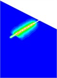
a) Condition 1
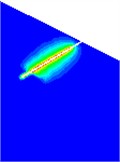
b) Condition 3
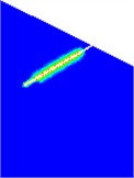
c) Condition 5
3.2. Analysis of pressure along the diffusion path of slurry
The pressure distribution of slurry diffusion along the slope in the gravel soil layer is shown in Fig. 3. The pressure distribution of slurry diffusion along the slope in the sand soil layer is shown in Fig. 4. The longitudinal section of slurry diffusion under some working conditions is shown in Fig. 5.
The simulation results show that the farther the distance between the slurry and the grouting pipe, the lower the pressure, until it decays to 0.
The attenuation rate of pressure is inversely proportional to the water cement ratio of the cement slurry. The larger the water cement ratio, the slower the attenuation rate. When the water cement ratio is 0.5, the attenuation is the fastest, followed by 0.8, and when the water cement ratio is 1, the attenuation is the slowest.
The attenuation rate of pressure decreases from fast to slow, and at the same time, the attenuation rate of pressure along the slope in the gravel soil layer is much slower than that in the sand soil layer. In the slope gravel soil layer, the pressure decays by about 55 % at a distance of 60 cm from the grouting pipe when the water cement ratio is 1. The pressure decreases by about 65 % at a distance of 60 cm from the grouting pipe when the grouting pressure is 0.4 MPa and the water cement ratio is 0.8. The pressure decreases by about 80 % at a distance of 30 cm from the grouting pipe when the water cement ratio is 0.5.
In sandy soil layers, the pressure decreases by about 60 % at a distance of 20 cm from the grouting pipe when the water cement ratio is 1. The pressure decreases by about 70 % at a distance of 20 cm from the grouting pipe when the water cement ratio is 0.8. The pressure decays to 0 at a distance of 20 cm from the grouting pipe when the water cement ratio is 0.5.
Fig. 3Distribution diagram of slurry pressure along the slope in gravel soil layer
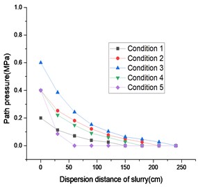
Fig. 4Distribution diagram of slurry pressure along the way in sandy soil layer
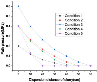
Fig. 5Partial working condition slurry diffusion longitudinal section pressure distribution diagram
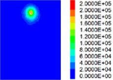
a) Condition 1
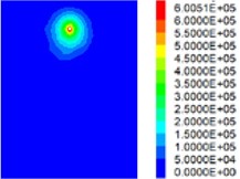
b) Condition 3
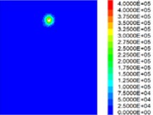
c) Condition 5
4. Conclusions
This article uses numerical methods to analyze the diffusion and flow laws of grout in slope gravel soil grouting. At the same time, the pressure distribution along the grout diffusion process and the changes in soil porosity and strength before and after grouting are analyzed.
1) The diffusion direction of the slurry is mainly perpendicular to the steel pipe, and it spreads in a cylindrical shape around the grouted steel pipe. The final diffusion radius of the slurry is proportional to the water cement ratio of the cement slurry and the grouting pressure. The diffusion radius of the slurry in slope gravel soil is much larger than that in sandy soil.
2) The farther the slurry is from the grouting pipe, the lower the pressure, until it decays to 0. The higher the water cement ratio, the slower the decay rate. The decay rate of pressure along the way decreases from fast to slow within the influence range of grouting pressure. At the same time, the attenuation rate of pressure along the slope in gravel soil layer is much slower than that in sandy soil layer
3) The porosity is reduced to a certain extent and the compressive strength is improved to a certain extent in both the slope gravel soil layer and the sand soil layer after they are reinforced by grouting.
The research results of this article have certain reference significance for the grouting research and engineering practice of slope gravel soil.
References
-
S. C. Li, X. Feng, and R. T. Liu, “Study on the law of grouting diffusion in sandy soil considering infiltration effect,” Rock and Soil Mechanics, Vol. 38, No. 4, pp. 925–933, 2017.
-
“Theory and engineering examples in rock and soil grouting,” Science Press, Beijing, 2001.
-
X. Z. Yang, X. H. Wang, and J. S. Lei, “Study and application of the diffusion radius of Binghan grout,” Journal of Hydraulic Engineering, No. 6, pp. 75–79, 2004.
-
X. Z. Yang, J. S. Lei, L. N. Xia, and X. H. Wang, “Study on diffusion radius of power-law grout,” Rock and Soil Mechanics, Vol. 26, No. 11, pp. 112–115, 2005.
-
Z. Q. Yang et al., “Study on column-hemispherical infiltration grouting mechanism of Bingham slurry with time-varying viscosity,” Rock and Soil Mechanics, No. 9, pp. 2697–2703, 2011.
-
F. Bouchelaghem, L. Vulliet, and D. Leroy, “Real-scale miscible grout injection experience and performance of advection-dispersion-filtration model,” International Journal for Numerical and Analytical Methods in Geomechanics, Vol. 25, No. 12, pp. 1149–1173, 2001.
-
Z. Q. Feng, “Development of chemical grouting reinforcement material for broken coal and rock mass and study on its infiltration and diffusion characteristics,” Coal Research Institute, Beijing, 2007.
-
L. Z. Wang, “Numerical simulation of particle flow in flexible pipe reinforced grouting,” Railway Survey, Vol. 36, No. 1, pp. 49–51, 2010.
-
J. L. Ge, “Yan Qiao of grouting simulation test and its application,” Chinese Journal of Geotechnical Engineering, Vol. 19, No. 3, pp. 28–33, 1997.
-
P. Yang et al., “Experimental study on grouting in sand and gravel layer,” Chinese Journal of Geotechnical Engineering, Vol. 28, No. 12, pp. 2134–2138, 2006.
-
J. S. Lei, “Study on mechanical behavior of grouting reinforcement of gravel soil foundation,” China University of Geosciences, Wuhan, 2013.
-
Z. Q. Yang et al., “Technological parameters of reinforced coarse-grained soil by grouting technology,” Electronic Journal of Geotechnical Engineering, Vol. 20, No. 27, pp. 13347–13356, 2015.
-
J. Y. Pang and W. J. Yao, “Grouting simulation test of loose water-rich sandy pebble bed and its engineering application,” Chinese Journal of Underground Space and Engineering, Vol. 15, No. 4, pp. 1156–1163, 2019.
About this article
The authors have not disclosed any funding.
The datasets generated during and/or analyzed during the current study are available from the corresponding author on reasonable request.
The authors declare that they have no conflict of interest.
