Abstract
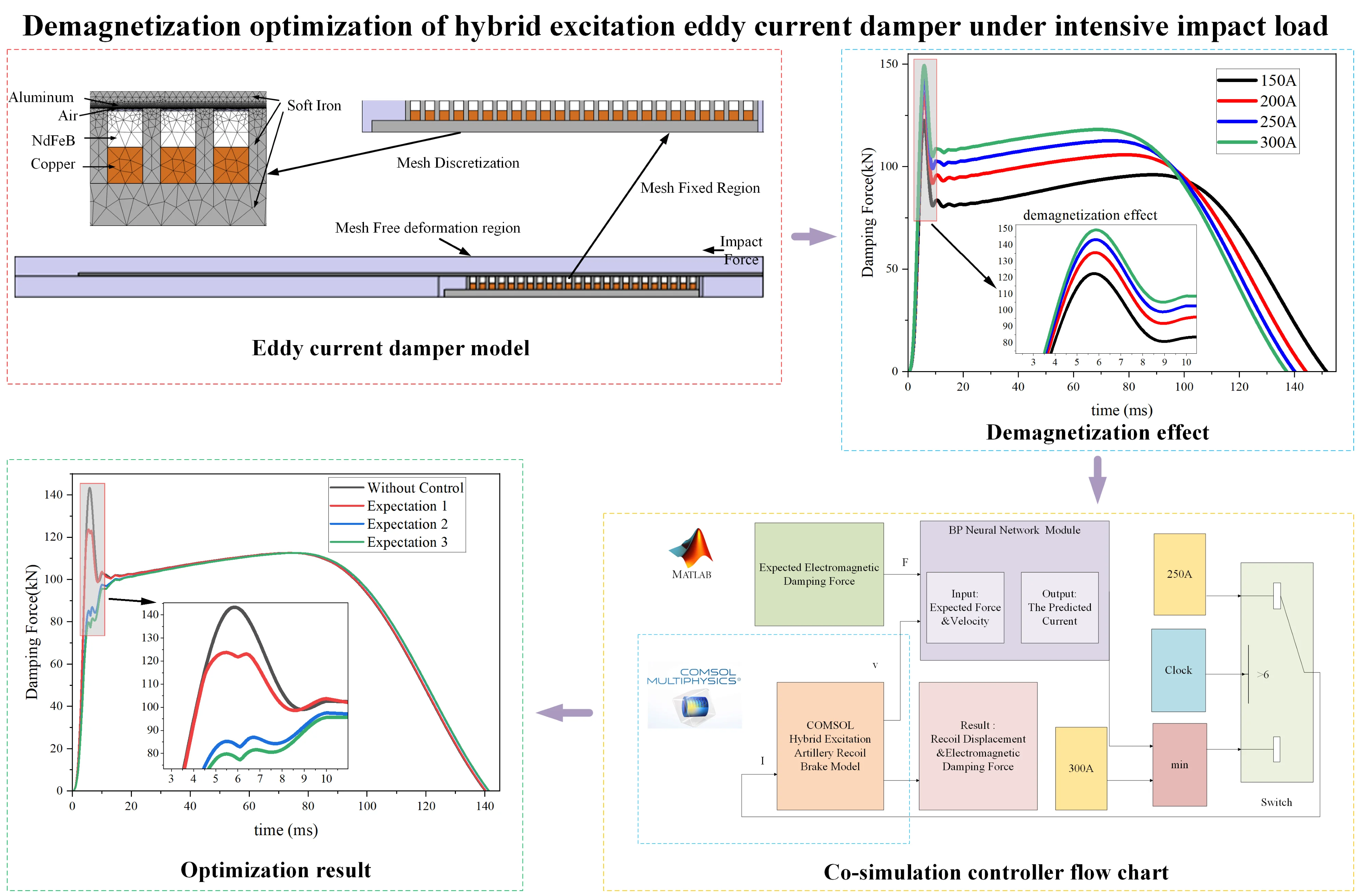
The hybrid excitation eddy current damper is a novel principle damper characterized by high reliability, simple structure, and controllable magnetic field. Under intensive impact loads, hybrid excitation electromagnetic damping can induce demagnetization effects, resulting in significant fluctuations of the electromagnetic damping force at 6-8 ms. To mitigate this phenomenon, this study established a finite element model of the hybrid excitation damper using COMSOL and developed a control module based on a BP neural network in Simulink. Through co-simulation of COMSOL and Simulink, the difference between the maximum and minimum electromagnetic damping force at 6-8ms is reduced from 45 kN to 5 kN. This research provides valuable technical references for the optimization and practical application of eddy current dampers.
Highlights
- Eddy current damper is innovatively applied to artillery.
- A complex nonlinear model is predicted using a neural network.
- Co-simulation is employed to control the eddy current damper.
1. Introduction
Eddy current damper can be categorized based on the primary excitation source into permanent magnet type, electromagnet type, and hybrid excitation type. The permanent magnet eddy current damper can provide a strong magnetic field in the air gap, but the amount of permanent magnet material is too large, the cost is too high. The electrically excited eddy current damper can change the magnetic field by controlling the current. However, it suffers from limitations such as insufficient magnetic field and power-off failure. The hybrid excitation type eddy current damper generates the magnetic field in the air gap through a combination of permanent magnets and excitation current, offering advantages such as high electromagnetic damping force and controllable magnetic field. However, the demagnetization effect is inevitable once the relative motion velocity exceeds the critical velocity under intensive impact load [1]. The demagnetization effect refers to the reversible or even localized irreversible demagnetization of permanent magnets under high-speed and intensive-impact conditions, leading to a significant decrease in electromagnetic damping force. Li and Yang et al. [2, 3] investigates the causes of damping and demagnetization effects of electromagnetic dampers under strong impact loads and the adverse effects of demagnetization effects on electromagnetic dampers. On the basis of above work, this paper realized the demagnetization optimization through control of the excitation current.
COMSOL Multiphysics is a multi-physics simulation platform for simulating and optimizing practical engineering problems. Long et al. [4] built a finite element model of stepper motor in COMSOL. The electric field and magnetic field laws of stepping motor under different faults are obtained. Guo et al. [5] used COMSOL to build a 3D finite element model of a rotating mechanical motor. The induced electromotive force generated by the motor under different parameters is simulated and calculated. MATLAB Simulink is a visual simulation tool, which is convenient for dynamic system modeling and simulation, and is usually used to design control system models. The co-simulation of COMSOL and MATLAB Simulink enables the control module to be integrated into the fixed model, allowing real-time control simulation of the system. Gao et al. [6] used COMSOL and Matlab Simulink co-simulation. The electric excitation magnetic field control in the hybrid excitation magnetic levitation system is realized. The electromagnetic force fluctuation caused by the change of permanent magnetic field position is reduced.
Although there are many studies on electromagnetic damping, there are few studies on the control simulation of hybrid excitation electromagnetic damping using COMSOL and MATLAB Simulink co-simulation. In this study, a finite element model of the hybrid excitation type eddy current damper was established in COMSOL. The motion of the damper under constant current was simulate. A neural network-based control module was developed in MATLAB Simulink, and co-simulation with COMSOL was conducted. The research results show the optimization of electromagnetic damping force fluctuations caused by demagnetization effects under intensive impact loads was achieved by controlling the excitation current.
2. Structure selection of hybrid excitation eddy current damper
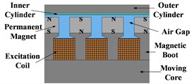
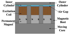
As the eddy current damper is subjected to intensive impact loads in research, the magnitude of the electromagnetic damping force becomes a crucial parameter. Therefore, it is necessary to study the arrangement of the excitation coils, permanent magnets, and magnetic boots.
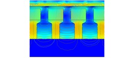
Fig. 1The structure and magnetic induction line distribution of the three schemes
a) The structure of scheme 1
b) The structure of scheme 2
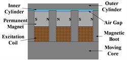
c) The structure of scheme 3
d) Magnetic flux density contour lines of scheme 1
e) Magnetic flux density contour lines of scheme 2
f) Magnetic flux density contour lines of scheme 3
According to the radial or axial direction of the magnetic field and the arrangement position of the excitation coil and the permanent magnet, the three arrangements of excitation coils, permanent magnets, and magnetic boots are shown below. Fig. 1(a) illustrates the structure of Scheme 1, where the excitation coils are placed between the magnetic boots with adjacent coils energized in opposite directions. The permanent magnet is arranged outside the magnetic boot and is magnetized along the radial direction. The polarity of the two adjacent permanent magnets is opposite. Fig. 1(b) shows the structure of Scheme 2, where the excitation coils are co-axially arranged with the permanent magnets between the magnetic boots. The permanent magnets are arranged on the inner side and magnetized along the axial direction. The polarity of the two adjacent permanent magnets is opposite. The coils are wound around the outer side of the permanent magnets, with adjacent coils energized in opposite directions. Fig. 1(c) depicts the structure of Scheme 3, where the excitation coils and permanent magnets are co-axially arranged between the magnetic boots. The coils are wound around the inner side of with adjacent coils energized in opposite directions. The permanent magnets are placed on the outer side, magnetized axially. The polarity of the two adjacent permanent magnets is opposite. Fig. 1(d), Fig. 1(e) and Fig. 1(f) are the magnetic flux density contours of the three structural schemes. The magnetic flux density of scheme 3 at the air gap is greater than that of scheme 1 and scheme 2. The electromagnetic damping force provided is greater. Therefore, scheme 3 is selected as the structure of hybrid excitation eddy current damper.
According to the structure of scheme 3, a simple analytical model of hybrid excitation eddy current damper is established. In the hybrid excitation eddy current damper, the magnetic field strength is provided by the permanent magnet and the excitation winding. It is assumed that the magnetic field strength generated by the permanent magnet in the axial direction is , the magnetic field strength generated by the excitation winding in the axial direction is , and the magnetic field strength provided by the excitation winding is proportional to the current through the winding, which can be expressed as follows:
where, is the number of turns per unit length of the winding.
When the permanent magnet and the excitation winding move along the axial direction, the eddy current density generated in the cylinder can be calculated by Eq. (2):
where, is the conductivity of the cylinder material, is the velocity, is the magnetic induction intensity, and is the permeability of the medium. The electromagnetic damping force generated by eddy current can be calculated by Lorentz force equation:
Because the magnetic field strength provided by the permanent magnet is constant, through the above derivation, two factors affecting the electromagnetic damping force are found: the excitation winding current and the velocity.
3. Establishment and simulation of COMSOL finite element model of eddy current damper
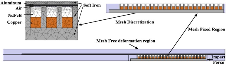
Firstly, the geometric model of the hybrid excitation eddy current damper is drawn in COMSOL, including the moving core, the excitation coil, the permanent magnet, the magnetic boot, the inner cylinder, the outer cylinder, and the surrounding air region, and then the corresponding material is added to each part. Detailed material distribution, meshing, mesh fixed region, mesh free deformation region and the location of the impact force are shown in Fig. 2. The mesh is divided by using the free triangular mesh in COMSOL.
Fig. 2Damper structure, material, meshing and boundary condition setting
In the electromagnetic field simulation, the main basis for COMSOL to distinguish different materials is the relative permeability, relative permittivity, electrical conductivity, residual magnetic flux density magnitude and other parameters set in the material. The parameters of the materials used in this paper are shown in Table 1.
Table 1Material parameter setting
Material | Relative permeability | Relative permittivity | Electrical conductivity / (S/M) |
Air | 1 | 1 | 0 |
Aluminum | 1 | 1 | 3.774×10⁷ |
Copper | 1 | 1 | 5.998×10⁷ |
B-H curve | Relative permittivity | Electrical conductivity | |
Soft iron (with losses) | COMSOL pre-set | 1 | 1.12×10⁷ |
Residual magnetic flux density magnitude | Relative permittivity | Electrical conductivity | |
NdFeB | 1.443 | 1 | 6.25×10⁵ |
The magnetic field is added to the physical field of COMSOL, and the properties of each part of the material are given to the electromagnetic field. The magnetic direction of the permanent magnet is set; the number of turns of the coil, the size and direction of the coil current are set at the excitation winding. The global differential equation is added to the physical field of COMSOL, and the differential equations of displacement, velocity and acceleration are added. The dynamic mesh is added to the physical field of COMSOL, and the displacement obtained by the differential equation of motion is given to the dynamic mesh of the moving part of the eddy current damper. Through the coupling of magnetic field, motion differential equation and dynamic mesh, the motion law and magnetic field law of eddy current damper can be obtained.
Fig. 3COMSOL simulation results of hybrid excitation Eddy current damper under constant current
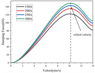
a) Damping force with velocity
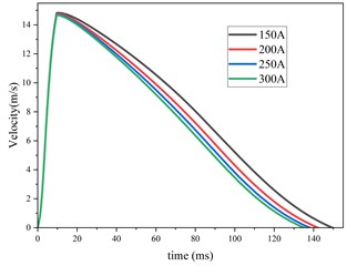
b) Velocity with time
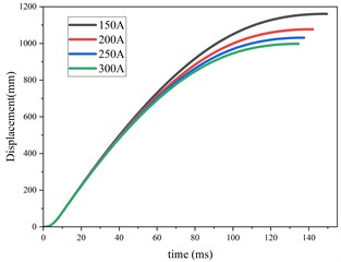
c) Displacement with time
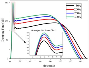
d) Damping force with time
Based on the above finite element model of eddy current damper, the constant current of 150 A, 200 A, 250 A and 300 A is applied to the excitation winding respectively. The motion law and the variation law of electromagnetic damping force under different constant current conditions are obtained in COMSOL as shown in Fig. 3. Fig. 3(a) shows the change of eddy current damping force with respect to velocity. It can be found that no matter how the constant current changes, when the velocity exceeds the critical velocity, the electromagnetic damping force will decrease. Fig. 3(b) shows the change of velocity with time. It can be found that the peak value of velocity remains unchanged no matter how the constant current changes. As the constant current increases, the time required to reduce the velocity to 0 is gradually shortened. Fig. 3(c) shows the change of displacement with time. It can be found that with the increase of constant current, the total displacement of motion decreases gradually. Fig. 3(d) shows the change of eddy current damping force with time. It can be found that the larger the constant current is, the larger the eddy current damping force is. However, no matter how the constant current changes, the demagnetization effect will occur at 6 ms, resulting in a sudden decrease in eddy current damping force.
4. Co-simulation of COMSOL and Simulink
In MATLAB Simulink, a control process was designed. Through the previous derivation, it was found that the electromagnetic damping force is influenced by two key factors: velocity and excitation current. Velocity and electromagnetic damping force are used as features, while the current magnitude is the target. From the simulation data of the constant current eddy current damper in COMSOL, 3100 samples were extracted, as shown in Table 2. Of these samples, 70 % were used as the training set, 15 % as the validation set, and 15 % as the test set. A BP (Backpropagation) neural network optimized using the Levenberg-Marquardt algorithm was then constructed.
Table 2Sample data
Serial number | Current | Velocity | Damping force |
1 | 0 | 1.632 | 7422.079 |
2 | 0 | 4.429 | 35291.390 |
… | … | … | … |
3100 | 300 | 7.227 | 107803.824 |
The samples are input into the neural network for training. The evaluation results of the trained model are shown in Table 3. The of the training set, the validation set and the test set are all above 0.97, indicating that the trained neural network model can accurately describe the influence of speed and electromagnetic damping force on the current size.
Table 3The evaluation results of the determination coefficient of the neural network model
Parameter | Training | Validation | Test | All |
0.9755 | 0.992 | 0.972 | 0.977 |
For the eddy current damper designed in this paper, the demagnetization effect mainly occurs in the 4-6 ms of motion. Therefore, the trained neural network model is mainly applied to the 0-6 ms of motion. The expectation of the electromagnetic damping force and the real-time output velocity in COMSOL are input into the neural network module at the same time. The neural network module calculates the corresponding current value and returns it to the COMSOL module. After 6 ms of motion, the constant current is passed to the excitation winding. The control process is as shown in the Fig. 4.
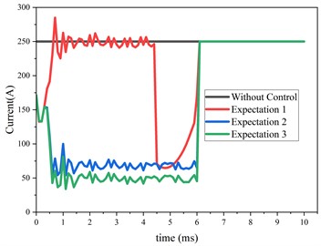
The designed control process was then applied to the eddy current damper model for control simulation. By continuously adjusting the expected electromagnetic damping force, control results for the damper under various expectation were obtained. Fig. 5(a) shows the variation of the electromagnetic damping force over time for different expectation and without control. It can be observed that controlling the current with the designed controller effectively mitigates the huge fluctuations in electromagnetic damping force caused by demagnetization effects. By continually adjusting the expectation, the control performance was optimized, achieving a reduction in electromagnetic damping force fluctuations at 6-8 ms from 45 kN to 5 kN. Fig. 5(b) and (c) display the displacement and velocity over time under different expectation and without control. It is noted that while the maximum displacement and maximum velocity under control are slightly increased compared to those without control, the changes in displacement and velocity are minimal, preserving the original performance of the eddy current damper. Fig. 5(d) shows the current curves computed by the controller under different expectation. It can be seen that the controller operates by applying a smaller current to the excitation coil before demagnetization effects occur, and a larger current after demagnetization effects arise, to compensate for the reduction in the magnetic field caused by the demagnetization of the permanent magnets.
Fig. 4Controller design flow chart
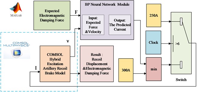
Fig. 5Comparison of results under different expectation and without control
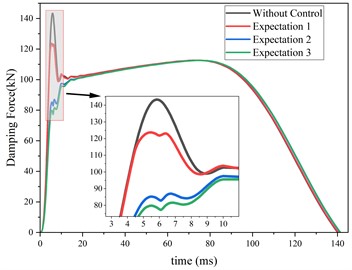
a) Damping force with time
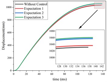
b) Displacement with time
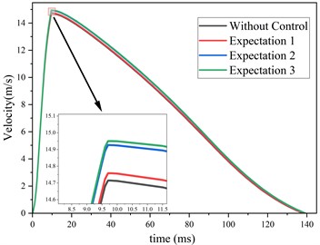
c) Velocity with time
d) Current with time
5. Conclusions
In this paper, co-simulation of COMSOL and MATLAB Simulink is used to simulate the electromagnetic field of the hybrid excitation eddy current damper, and the demagnetization effect is optimized by adjusting the current. Specifically, the hybrid excitation eddy current damper with constant current in the excitation winding will produce a demagnetization effect during the recoil process, resulting in a huge fluctuation in the electromagnetic damping force. The control module is built in MATLAB Simulink, and the co-simulation of COMSOL and MATLAB Simulink is used to reduce the huge fluctuation of electromagnetic damping force. Judging from the results, the demagnetization effect is optimized. The difference between the maximum and minimum electromagnetic damping force at 6-8 ms is reduced from 45 kN to 5 kN.
References
-
S. Wu, X. Wang, S. Cui, and W. Zhao, “Risk evaluation for hybrid excitation compulsator,” in IEEE Transactions on Plasma Science, Vol. 43, No. 5, pp. 1410–1414, May 2015, https://doi.org/10.1109/tps.2015.2416194
-
C. Li, G. L. Yang, and L. Li, “Experimental study and numerical simulation of demagnetization behavior of sintered NdFeB used in eddy current brake,” Journal of Ballistics, Vol. 35, No. 2, pp. 53–59, 2023.
-
Z. Li, G. Yang, and L. Wang, “Damping and demagnetization analysis of a cylindrical linear electromagnetic buffer under impact load,” International Journal of Applied Electromagnetics and Mechanics, Vol. 66, No. 2, pp. 265–282, Jun. 2021, https://doi.org/10.3233/jae-201556
-
Y. J. Long, J. F. Wang, J. F. Qian, and W. B. Zhao, “Research on the change law of current and magnetic field of stepper motor fault based on COMSOL,” (in Chinese), Small and Special Electrical Machines, Vol. 52, No. 4, pp. 44–48, 2024.
-
J. Guo, J. C. Liu, Y. Jia, and J. T. Yu, “Simulation analysis of rotating machine alternator based on finite element analysis software COMSOL,” (in Chinese), Manufacturing Automation, Vol. 34, No. 17, pp. 53–56, 2012.
-
T. Gao, J. Yang, F. Z. Zhou, and Z. H. Cao, “Design and analysis of a permanent magnet electromagnetic hybrid levitation control experiment based on COMSOL,” (in Chinese), Experimental Technology and Management, Vol. 41, No. 3, pp. 165–174, 2024.
About this article

The research was supported by “China National Postdoctoral Program for Innovative Talents” (Grant No. BX20230493), “the National Natural Science Foundation of China” (Grant No. 52305155), “Open Project of Chinese Scholartree Ridge State Key Laboratory” (Grant No. AF20240029).
The datasets generated during and/or analyzed during the current study are available from the corresponding author on reasonable request.
The authors declare that they have no conflict of interest.
