Abstract
The permanent magnet eddy current brake (ECB) discussed in this paper are expected to brake a strong impact load for a large-scale machinery, and its design requirement is to brake smoothly within a given displacement limit. A design method is proposed to be able to design and calculate the based on the design requirements. According to the requirements of the brake displacement, an expected brake force can be calculated. Then, through the analysis of the permanent magnet operating point and the analysis and calculation of the design parameters, a reasonable design scheme that matches the prime design requirements can be obtained. When facing strong shock loads, in addition to satisfying braking requirements, different shock conditions can lead to different practical braking process. Making the corresponding braking process smoother can be regarded as an additional design objective, thus the design scheme obtained can be optimized in a certain range accordingly. A multi-objective optimization design of the ECB is carried out in combination with the Stackelberg game theory. After verifying the optimization results, it can be obtained that the given design and optimization methods are applicable and can satisfy the design and optimization objectives.
1. Introduction
Eddy current brake is a braking structure that generates electromagnetic resistance through eddy current losses. A cylindrical permanent magnet ECB intended for braking strong impact loads and its design method will be investigated in this paper.
The research related to ECB are still more on the direction of its application [1-4], predictive modeling and resistance characterization. In some ECB studies, scholars will give some design-related analysis when performing parametric characterization [5]. There are also some studies applying design logic. Kou et al. presented a design method of hybrid excitation ECB based on design indexes [6]. Ye et al. proposed a design method for a hybrid excitation detractor for a small-caliber artillery gun based on the design of the detractor force curve and the ECB parameter analysis [7].
When designing for specific impact loads, making the corresponding braking process smoother can be regarded as an additional design objective. For example, a stronger load may lead to higher acceleration and velocity that makes the braking process more chaotic, and the mass and braking distance can make concessions. Some studies have used multi-objective optimization methods to find design parameters [8-9]. In the optimization study of ECB, Xu proposed to combine the nash game with multi-objective optimization and obtained the design results that satisfy the optimization objectives [10].
The application of ECB to artillery anti-recoil device is the latest research direction to explore its application field. In this paper, its design method will be carried out. Most of the current research on the design method of ECB is still through characteristic analyzing. To conduct further research on the design methodology, this paper proposes a more explicit design method to calculate the design parameters of ECB by deduction from the design requirements and indexes. According to the brake displacement requirements, an expected brake force can be calculated. Then, through the analysis of the permanent magnet operating point and the analysis and calculation of the design parameters, a reasonable design scheme that matches the prime design requirements can be obtained. Based on the obtained design scheme and additional design requirements, a multi-objective optimization design of the ECB is carried out in combination with the Stackelberg game theory. and the optimization results are verified by FEM modes.
2. Braking motion model and expected value of electromagnetic resistance
2.1. Motion model of the braking process
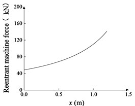
The ECB model applied on the artillery recoil device will be investigated in this paper, and its braking process will be calculated and designed. The ECB is subjected to a strong impact bore force load and brakes under the action of electromagnetic resistance with the resistance generated by the reentry mechanism. The strong impact load varies with time, as is shown in Fig. 1. During the braking process, in addition to the electromagnetic resistance , the braking machine also receives a reentrant machine force that varies with displacement, shown in Fig. 2, and gravitational force . Based on the above force analysis the motion equations are established:
where is the displacement and is the attitude angle.
Fig. 1Impact load
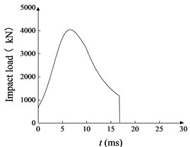
Fig. 2Resistance of reentry mechanism
2.2. Expected value of electromagnetic resistance
The ECB electromagnetic resistance curve with respect to the velocity presents a certain shape pattern. Based on the resistance characteristics of the ECB, a formula can be presupposed for it with velocity as the variable, which divides it into two segments that vary with velocity:
In combination with Eq. (1), a set of differential equations of motions for the braking process can be obtained. Given the boundary conditions, i.e., the maximum braking displacement given by the design requirements, the expected value of electromagnetic resistance can be obtained.
3. Design and calculation of ECB
3.1. ECB electromagnetic field model and operating point analysis of permanent magnets
Fig. 3 gives a partial three-dimensional structural view of the investigated cylindrical permanent magnet (PM) ECB. Fig. 4 shows a simplified view of the magnetic circuit in the ECB, where the magnetic field is generated by PMs, and the magnetic circuit follows the iron pole through the air gap and the conductor layer to connect with the outer cylinder, and the magnetic leakage is simplified in the figure.
Fig. 3Partial structure of PM eddy current brake: 1 – the shaft, 2 – PM, 3 – iron pole, 4 – conductor cylinder, 5 – outer cylinder
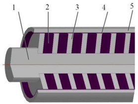
Fig. 4Simplified magnetic circuit of ECB
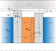
The magnetic circuit at the air gap and the conductive layer represents the working magnetic circuit. Assuming the magnetic circuit distribution is uniform in all parts, the magnetic potential loss in the outer cylinder is neglected, and magnetic saturation be assumed negligible. According to Kirchhoff’s law of magnetic circuits with the demagnetization curve of permanent magnets, it can be obtained:
where , , , , , , , are the magnetic flux density, the magnetic field strength, the cross-sectional area and the length of the PM and working magnetic circuit, respectively. and is the remanent magnetization of the permanent magnet. The magnetic permeability of the conductive layer is generally the same as that of air, so the can be obtained:
According to the electromagnetic induction law and the eddy current loss, the electromagnetic resistance of the ECB can be calculated:
The slope of the PM load line can be obtained based on Eq. (3). In order to maximize the utilization of the magnetic energy in PMs, the closer the PM operating point is to the value on the demagnetization curve, the better. The corresponding PM size ratio can be obtained:
where , , is the semi diameter of the middle layer between the air gap and the inner cylinder section, as shown in Fig. 4. In the actual design, due to the limitation of ECB structure, most likely cannot reach the optimal operating point, but this formula can be used as the initial design point.
3.2. Air gap width, thickness of conductor and outer cylinders
The air gap width is one of the core parameters of ECB. Generally, the narrower the air gap is, the stronger the magnetic field and the higher the resistance will be. However, when the air gap width is smaller than a certain value, the assembly will not be guaranteed. Similarly, the conductor cylinder thickness is also limited by mechanical manufacturing and assembly constraints. Therefore, these two dimensions should be set as a minimum according to the capabilities of the mechanical manufacture as well as the assembly.
Due to the strong impact, the thickness of the outer cylinder should be able to ensure structural stability. At this situation, it won’t have a great influence on the electromagnetic resistance, and its value should be decided according to the overall size of the brake.
3.3. Calculation of the PM number, preliminary design of size of PM and iron pole
The PMs are the core structure of the ECB, and the dimensions of other components show a certain proportional relationship with it. A set of conventional proportions can be given in the preliminary design:
where is the thickness of iron poles, is the radius of the shaft, is the radial width of the PM, and is the difference between the radial width of the iron pole and PM. That is to say, the parameters to be obtained in the preliminary design are , and the PM stage number , the rest of the parameters can be determined according to them.
Starting from the of the optimum operating point, the test calculations can be carried out. According to the prediction model, the resistance generated corresponding to a single set of PM and iron pole can be obtained. According to Eq. (2), can be set as the resistance at the critical speed. According to given in Section 2.2, can be obtained:
where is rounded to the nearest whole number. Once the is obtained, the / ratio of the overall ECB can be obtained, the diameter of ECB is the outer cylinder diameter, and the length is given by:
Considering the rationality of the mechanical structure, the / ratio can be limited to 10~12. In general, it is necessary to gradually increase the from the of the optimal operating point and then carry out trial calculations until the / ratio meets the requirements.
4. Multi-objective optimization using the Stackelberg game theory
4.1. Optimization modeling with the Stackelberg game theory
The preliminary design of an ECB was carried out by the proposed design flow and two sets of designs are obtained. Its , were given in Figs. 1-2, and the rest of the parameters were given in Table 2. According to analyze in introduction, the design can be further optimized within the design range formed by the two design solutions.
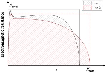
In addition to the maximum braking distance , the optimization objective electromagnetic resistance profile sufficiency FCMD was proposed, as in Eq. (11). The multi-objective optimization model is given in Eq. (10). Fig. 5 shows the meaning of FCMD, when the electromagnetic resistance behaves smoothly at high speed and the maximum braking distance is short, the will presents large, and the braking smoothness will be better.
It can be noticed that these two optimization objectives are interrelated, while the should always be the dominant objective, which is similar to the case of the Stackelberg game theory.
Fig. 5Schematic diagram of electromagnetic resistance profile sufficiency FCMD
A Stackelberg game consists of players, strategy and payoff. There are two types of player: leader and followers. Corresponding to the multi-objective optimization model, the two players are leader and follower . The strategy is that the arrangement made by player be in response to the actions made by the other player. Set the parameters (, , , , ) as design variables . And they are grouped in and , corresponding to the leader and follower. The upper and lower bound of the and are given in Table 1. During the calculation of optimization, also varies with the design variables:
Table 1Range of design variables
Design variables | / mm | / mm | / mm | / mm | / mm |
Upper bound | 28 | 52.5 | 3 | 22 | 10 |
Lower bound | 33 | 50 | 1.5 | 19.5 | 6 |
4.2. Game results and its verification
During the game, the leader first operates the optimizer to find min () by adjusting . Then, with remaining the result of leader, the follower operates the optimizer to find min (-FCMD) by adjusting . The is passed to the leaders move again and the two players take turns to find the optimization strategy. When the leader cannot improve its strategy, it is considered that a Stackelberg equilibrium is reached. The convergence process of game is shown in Fig. 6, which shows the decision result history of the two players. The equilibrium results of the game model is shown in Table 3.
Table 2Additional parameters of eddy current recoil brake
Parameter | Value | Parameter | Value | Parameter | Value | Parameter | Value |
0.5 mm | Thickness of outer cylinder | 8.5 mm | Max | 1 m | 32 | ||
1.5 mm | Conductivity of conductive cylinder | 35.4 MS/m | Max L/D ratio | 11 | 28 | ||
1.45 T | Conductivity of outer cylinder | 10 MS/m | M | 3400 kg | 22.4° |
Table 3Values of design variables
Variables | / mm | / mm | / mm | / mm | / mm |
Stackelberg equilibrium | 33 | 52.5 | 2.3 | 21.2 | 8.3 |
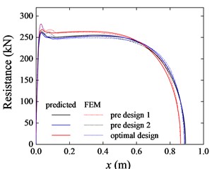
FEM models were built using the design of equilibrium point data and two preliminary design. Fig. 7 shows the electromagnetic resistance during braking process of the three FEM models. It can be seen that the resistance of the optimized design performs more smoothly and ends the braking faster. The optimization calculation using the prediction model resulted in the optimization of from 0.897 m versus 0.892 m to 0.866 m. Despite the slight inaccuracy, the FEM results of were also reduced from 0.888 m and 0.884 m to 0.863 m, and the resistance of optimized design behaved in a smoother manner. This indicates that the applying of the Stackelberg game in optimization model can obtain design results that satisfy the optimization demands.
Fig. 6Convergence histories of the two players
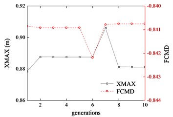
Fig. 7Resistance of the equilibrium point
5. Conclusions
According to the requirements of the brake displacement and motion equations of the braking process, an expected brake force can be calculated. Then, through the analysis of the permanent magnet operating point and the analysis and calculation of the design parameters, preliminary design scheme can be obtained. Based on the obtained design scheme and given design requirements, a multi-objective optimization design of the ECB is carried out in combination with the Stackelberg game theory. And the optimization results verified by FEM modes indicates the multi-objective optimization incorporating the Stackelberg game strategy can be applied.
References
-
B. Ebrahimi, H. Bolandhemmat, M. B. Khamesee, and F. Golnaraghi, “A hybrid electromagnetic shock absorber for active vehicle suspension systems,” Vehicle System Dynamics, Vol. 49, No. 1-2, pp. 311–332, Feb. 2011, https://doi.org/10.1080/00423111003602400
-
Z. Wang et al., “Experimental study on vibration control of a model footbridge by a tiny eddy-current tuned mass damper with permanent magnets,” (in Chinese), Journal of Vibration and Shock, Vol. 20, pp. 129–132, 2014, https://doi.org/10.13465/j.cnki.jvs.2014.20.025
-
Y. Jin, B. Kou, and L. Li, “Improved analytical modeling of an axial flux double-sided eddy-current brake with slotted conductor disk,” IEEE Transactions on Industrial Electronics, Vol. 69, No. 12, pp. 13277–13286, Dec. 2022, https://doi.org/10.1109/tie.2021.3139236
-
Y. Fan, G. Yang, J. Li, H. Zhang, and L. Wang, “Analytical modeling of permanent magnet linear eddy current brake using magnetic equivalent circuit method,” International Journal of Applied Electromagnetics and Mechanics, Vol. 69, No. 1, pp. 67–86, May 2022, https://doi.org/10.3233/jae-210190
-
B. Ebrahimi, M. B. Khamesee, and F. Golnaraghi, “Eddy current damper feasibility in automobile suspension: modeling, simulation and testing,” Smart Materials and Structures, Vol. 18, No. 1, p. 015017, Jan. 2009, https://doi.org/10.1088/0964-1726/18/1/015017
-
Kou B. et al., “Analysis and design of hybrid excitation linear eddy current brake,” IEEE Transactions on Energy Conversion, Vol. 29, No. 2, pp. 496–506, Jun. 2014, https://doi.org/10.1109/tec.2014.2307164
-
J. Ye, “Analysis and design of hybrid excitation artillery retracting machine,” (in Chinese), North University of China, 2020.
-
W. Chen, B. Kou, M. Wang, and X. Niu, “Speed-based multiobjective optimisation of a cage-secondary permanent magnet linear eddy current brake,” International Journal of Systems Science, Vol. 54, No. 4, pp. 835–848, Mar. 2023, https://doi.org/10.1080/00207721.2022.2146989
-
M. Yao, J. Miao, S. Cao, S.A. Chen, and H. Chai, “The structure design and optimization of electromagnetic-mechanical wedge brake system,” IEEE Access, Vol. 8, pp. 3996–4004, Jan. 2020, https://doi.org/10.1109/access.2019.2962559
-
F. Xu, G. Yang, Z. Li, L. Wang, and Q. Sun, “Electromagnetic buffer optimization based on Nash game,” Acta Mechanica Sinica, Vol. 37, No. 8, pp. 1331–1344, Jul. 2021, https://doi.org/10.1007/s10409-021-01101-2
About this article

The authors have not disclosed any funding.
The datasets generated during and/or analyzed during the current study are available from the corresponding author on reasonable request.
The authors declare that they have no conflict of interest.
