Abstract
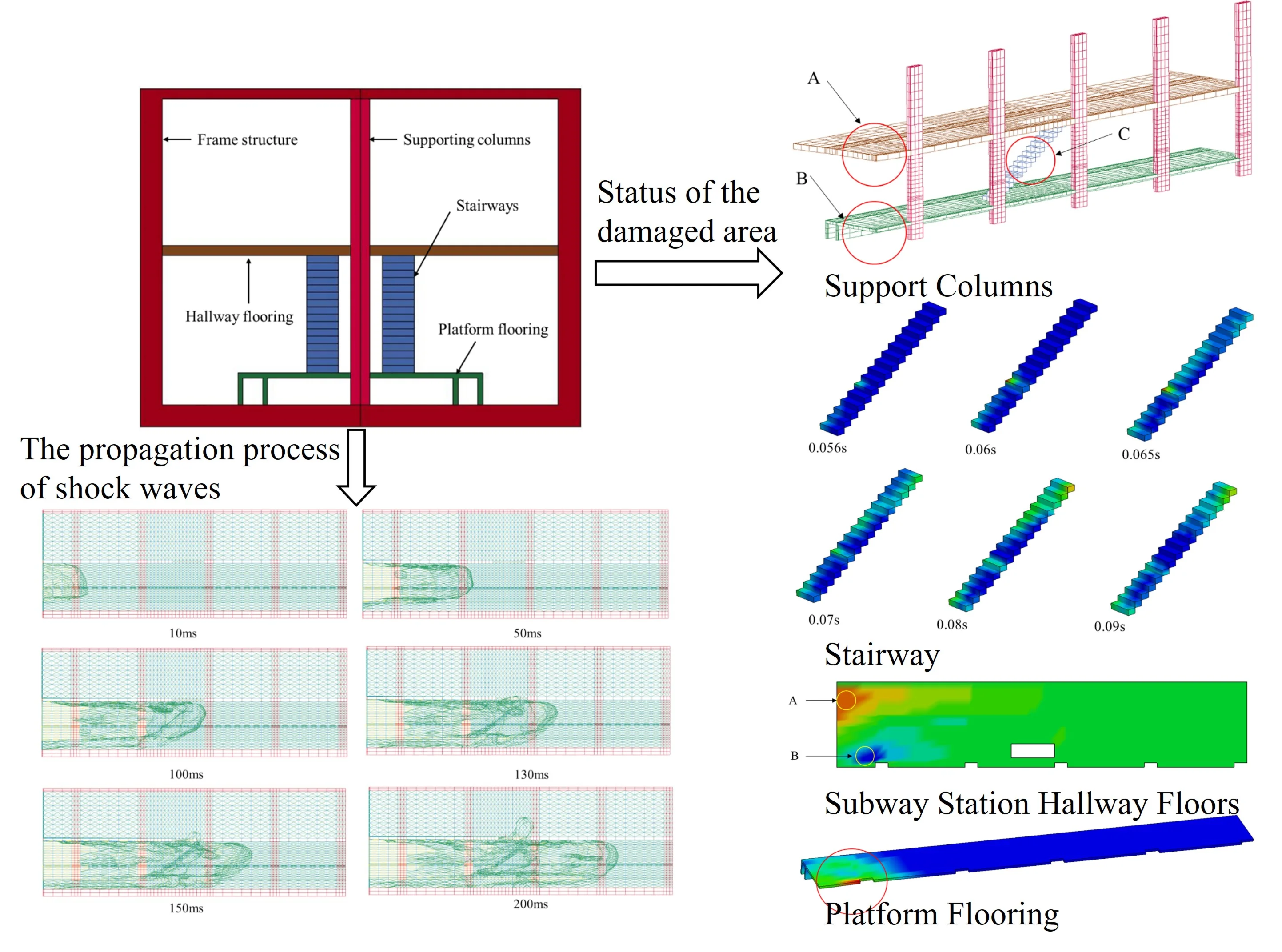
As the subway station space is closed and the passenger flow is large, subway explosion-proof has always been the focus of station safety personnel. Here we built typical two-story and two-span underground stations model by using LS-DYNA. Through ALE algorithm and fluid structure coupling method, propagation law of shock wave in subway station and damage state of station structures were analyzed in the case of 16.3 kg TNT explosion. It is found that the shock wave mainly propagates along the lateral direction of the station after the superposition and attenuation of the surrounding structures. The maximum displacements of supporting columns, subway stairways, hallway flooring and platform flooring are 1.34 mm, 16.83 mm, 5.354 mm and 112.8 mm respectively. And the overall structure of the station is complete, but local areas are damaged and collapsed. In addition, in order to strengthen the antidetonation stability of subway station structure, the joint of column and platform floor, the joint of column and station hall floor and the reinforcement of stairs should be considered. This paper mainly provides a theoretical basis for the explosion-proof design of station structure.
Highlights
- Analysis of the whole process of subway model explosion is proposed.
- The effects of different structures in subway, such as supporting columns, subway stairways, hallway flooring and platform flooring, on explosion impact are given.
- The weak links of subway structure are given emphatically.
1. Introduction
Urban rail transit is a new mode of transportation designed to ease increasingly congested roads. At the present time, there are still more than 100 subway lines in the construction planning stage in 50 cities in China. However, there are many potential safety hazards due to the closeness of subway stations, large passenger flow rates, and other characteristics. The most damaging incident which has occurred was an explosion inside a subway station. When an explosion accident caused by a terrorist attack occurs in a subway station, it will potentially cause serious personal injury and property loss and seriously threaten the security of a city. Considering the complexity of subway structures and the various equipment and facilities required within a station, investigations regarding the influencing effects of complex environmental factors on the propagation of explosion shock waves inside subway stations, as well as the mechanical responses of subway internal structures undergoing explosive impacts, will be of major important theoretical significance and provide a certain basis for the future designs of subway structures.
For the propagation law of explosion waves, the empirical or semi-empirical methods used to calculate the explosion overpressure in engineering fields are generally based on test results or hypotheses of open fields [1, 2]. Previously, many researchers began to use numerical simulation methods to study explosion events in complex environments. Smith and Mays et al.[3] applied model testing and numerical simulation methods, respectively, to study the propagation law of explosion waves and overpressure loads in underground closed structures. Bretislav Janovsky [4] conducted experimental research and numerical simulations on confined explosions in tunnels under ventilation conditions. Van den Berg et al. [5] examined the fracture and explosion effects of 50 m3 liquefied petroleum gas (LPG) containers in tunnel scenarios. Mohd Shahrom Ismail et al. [6-8] analyzed the influence of vibration on composites through experiments and numerical simulation. In another related study, Giannopoulos [9] used a laser scanning method to obtain the geometric model of a subway station and carriage, and then used the risk analysis module in a Euro-plus analysis program to analyze the damage ranges of shock waves after explosion events in the station and carriage. Besides, some studies focused on simulating the concrete and steel element by finite element method [10-12]. Jianwei Cheng et al. analyzed the influencing factors of the underground confined space under the action of explosion and established the damage structure model of the mine seal [13, 14]. Luo Kunsheng et al. [15] respectively studied the shock wave propagation processes and analyzed the mechanical responses of subway running tunnels, as well as the ground above the tunnels, using a numerical simulation method. Some scholars have studied explosion related problems by combining numerical simulation with field experiments [16, 17]. Du Xiuli et al. [18] studied the propagation law of the explosion waves inside stations and the damage mechanism of the columns located inside subway stations. The propagation and attenuation laws of the explosion waves inside the subway stations were also examined by Qu Shusheng et al. [19], who recommended safe distances to be maintained in order to avoid personal casualties and death when the explosions occur. Li Shiqiang et al. [20] used AUTODYN to study the propagation law of explosion waves in the platform layers of subway stations, and successfully determined a personnel death range. Hu Weisheng [21] investigated the overpressure attenuation law of explosion shock waves in typical subway stations. Zongyao Hu et al. [22]analyzed the explosion simulation results without escalator witch used LS-DYNA.
In previous related studies, the impacts of internal explosions in subway station have been investigated. According to the metro design code and the design of typical terrain stations in China, for typical two-story stations, only minimal attention has been focused on analyzing the impacts of explosive shock waves in the presence of stairways. In this study, typical two-story and two-span underground stations were examined, and the influencing effects on the propagation of explosion shock waves of platform flooring, station hallway flooring, interior columns, and platform stairways were analyzed. In addition, the mechanical responses and damage states of the above-mentioned structural factors under the action of explosion shock waves were analyzed, which provided a certain theoretical basis for future explosion-proof designs for subway stations.
2. Model parameter selection and modeling
2.1. Modeling
A typical underground subway station was modeled in the current study, as shown in Fig. 1. The calculation model of the underground station was a two-story and two-span structure. The station width measured 18 m; station length was 38.5 m; platform floor height was 1.3 m; platform height of 5 m; and the station hall height was set as 6 m. Among the aforementioned dimensional guidelines, the thickness of the platform flooring was set as 0.2 m, and the thickness of the station hallway flooring was 0.4 m. There were four stairs in the model, extending from the platform floor to station hallway floor, located between Pillars 3 and 4 and Pillars 7 and 8, respectively, which were symmetrically distributed among the pillars, as shown in Figs. 2 and 3. The distance between the pillars was 8.5 m, and the cross-section size of the pillars measured 1.2 m×0.8 m.
Due to the symmetry of this study’s model, a ¼-scale model was selected for the modeling process in order to facilitate the calculation processes and reduce the calculation time. The TNT was set as a 16.3 kg cubic explosive, which was situated in the middle of the transverse distribution of the story containing the station platform. Then, by considering such factors as personnel carrying actions, the TNT was set to explode at a position of 1.6 m away from the platform floor.
2.2. Material constitutive model
The numerical model consisted of seven parts: TNT, air, station frame structure, columns, stairways, station hall flooring, and platform flooring. SOLID164 solid element was used for the modeling process, and a Lagrange algorithm was adopted for concrete structure. A Eulerian grid was used for the TNT, soil, and air. In addition, a multi-material ALE algorithm was used in the elements; *ALE-MULTI-MATERIAL-GROUP was used to define the multi-material element; and a common node coupling method provided in the LS-DYNA finite element program was adopted for the fluid-structure coupling calculations. Subsequently, the interactions between the explosion shock waves and subway station structure were successfully simulated. As the model used a ¼-size modeling technique, symmetrical constraints were applied to the cross sections and vertical sections of the explosion center perpendicular to the ground, and fixed constraints were adopted for the outermost interfaces of the model.
Fig. 1Internal structure model diagram of metro station
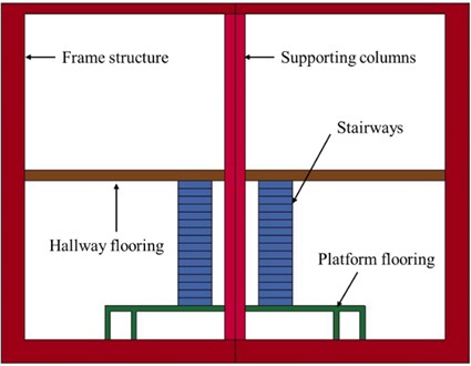
Fig. 2Section of internal structure of metro station
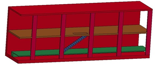
Fig. 3Location relationship between TNT and metro station

Air and explosive are calculated by ale grid division, explosive materials are simulated by high explosive materials, and air materials are assumed to be ideal gas for calculation. The air was defined using a *MAT-NULL air material model, and the explosive gas was defined using *EOS-JWL state equation and *MAT-HIGH-EXPLOSIVE-BURN explosive combustion material model [23]. Both of the aforementioned models used a linear polynomial state equation to describe the state change processes of the explosive gas products. The linear polynomial state equation was as follows:
where indicates the current density; denotes the initial density; is the internal energy of the explosive gas; and to represent the parameters of the state equation. The relevant parameters of the linear polynomial state equation are detailed shown in Table 1.
The selection of other material parameters of the model is shown in Table 2.
Table 1Parameters of linear polynomial equation
Material | Density (kg/m3) | (MJ·m-3) | ||||||||
Air | 1.29 | –0.1 | 0 | 0 | 0 | 0.4 | 0.4 | 0 | 0.25 | 1 |
TNT | 1630 | 0 | 0 | 0 | 0 | 0.274 | 0.274 | 0 | 3.408 | 1 |
Table 2Model material parameter values
Concrete structure | Density (kg/m3) | Elastic modulus (MPa) | Poisson’s ratio | Shear transfer coefficient of crack opening | Shear transfer coefficient of crack closure | Uniaxial tensile strength (MPa) | Uniaxial compression limit (MPa) | Softening cracking coefficient |
2400 | 30000 | 0.3 | 0.5 | 0.9 | 3 | 30 | 1 |
2.3. Reliability verification of numerical model
Pokrovsky obtained the attenuation formula of pressure peak value when air shock wave propagates along two directions of tunnel according to the principle of energy similarity law:
where indicates the blast wave peak overpressure; denotes the quality of TNT; is the cross sectional area of tunnel; and represent the distance from explosion center.
Based on the model and prototype test data, Charles Robert Welch et al. proposed the formula for the attenuation of shock wave peak overpressure along the constant cross-section tunnel [24]:
where indicates the blast wave peak overpressure; denotes the quality of TNT; is the tunnel diameter; represent the distance from explosion center; is the distance from explosion center to entrance; and is the ratio function, which and when an internal explosion occurs.
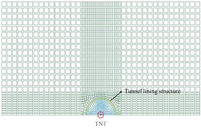
In order to verify the accuracy of the model parameters, the model of explosion in long straight tunnel is established, as shown in Fig. 4.
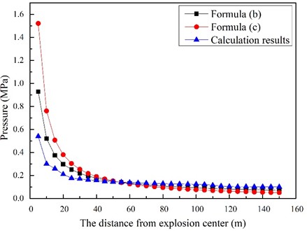
The model calculation results are compared with the above two formulas, as shown in Fig. 5. It can be seen that the trend of the three curves is roughly the same through data comparison.
In addition, the value of the distance within 5 m from the explosion source is lower than the predicted value of the formula, and the simulated value of the distance greater than 5 m is close to the predicted value of the formula. This may be caused by two reasons: 1) the influence of air grid size on the calculation results; 2) The air medium in the near explosive zone is no longer an ideal gas, which is different from the simulation calculation [25].
Fig. 4The structure of the verification model
a) Front view

b) Side view
Fig. 5Comparisons of the attenuation curves
3. Analysis of the explosive shock wave propagation
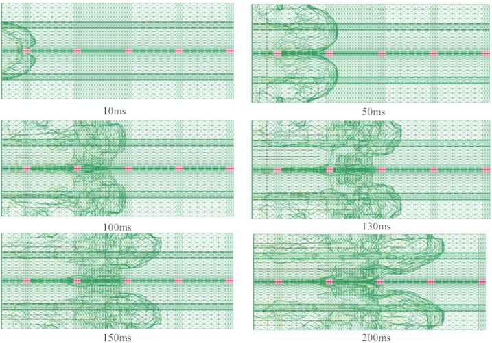
This study carried out numerical simulation analyses of TNT explosions in a typical subway station. The impacts of the explosion on subway station structure within a time range of 0 to 0.2 seconds were calculated. Figs. 6 and 7 show the longitudinal section and top view of the shock waves as they changed with time in the simulated subway station during different stages. The following results were observed: 1. The frame structure of the station, floor of the station hall, and floor of the platform reflected the shock waves, which caused the shock waves to superimpose and attenuate in the longitudinal direction; 2) When the shock waves reached the columns, in addition to the impacts on the columns, the column had blocked the shock waves and separated them into two parts. Then, the shock waves had continued to propagate forward, with one part of the shock waves reflected and superimposed on the surfaces of the columns, and the shock waves behind the columns declining rapidly; 3) When the shock waves reached the stairway area, the shock waves which were facing the stairs were reflected, superimposed, and reduced on the stairs. Then, as the stairway area passed through the station hallway and platform floor areas, part of the shock waves had propagated along the direction of the stairs to the station hallway floor, while other shock waves continued to propagate after crossing the stairs; 4) It was observed that with the passage of time, the outermost layers of shock wave had moved upward and were close to the roof of platform floor; 5) In addition, due to the complex structure of the station, the shock waves were repeatedly reflected, superimposed, and reduced on each of the structural features, which was found to have major impacts on the propagation law of the shock waves.
Fig. 6Time history of explosion impact pressure on subway station (longitudinal section)
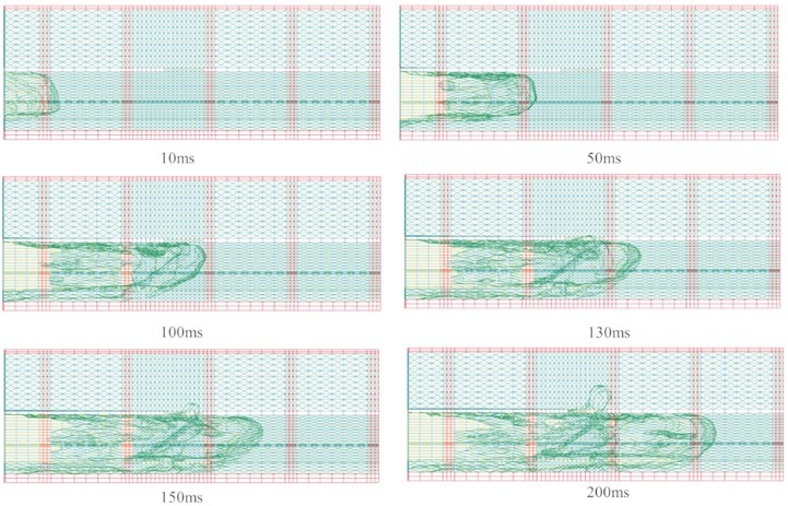
Fig. 7Time history of explosion impact pressure on subway station (top view)
3.1. Analysis of the pressure variations of the supporting columns subjected to shock waves
The supporting columns were found to play important roles in the stability of subway station structure. Once the supporting columns suffer destructive damages, the subway station could potentially collapse at any time, causing serious casualties. As shown in Fig. 8, nodes were evenly selected in the columns nearest the TNT, and nodes were also selected in the middle areas of other columns for the purpose of analyzing the obtained results.
Fig. 8Observation point distribution of supporting columns

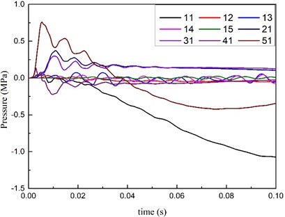
Fig. 9 details the time-dependent curves of the impact pressure on this study’s selected key points. In this study’s scenario, when the 16.3 kg TNT explosion occurred in the subway station model, the two columns closest to the explosion source were significantly affected. However, it was observed that other columns were also affected to varying degrees with distance from the source. Those columns were all located within the range of elastic deformations and no significant impacts on the structure of the building were observed. In the columns located closest to the explosion source, the pressure deformation of Point 11 was found to gradually increase, indicating that plastic deformations may occur at that point. Meanwhile, in the case of Point 51, which was also located close to the explosion source, the shock waves were found to first increase and then decrease due to the point’s position below the floor area.
Fig. 9Curve of impact pressure on key points of column with time
3.2. Analysis of the pressure variations of the subway stairways subjected to shock waves
It has also been confirmed that stairway areas are other important parts of subway station structures. However, they have seldom been studied in the past. This research investigation analyzed the impacts of TNT explosions on stairway areas in subway station. As shown in Fig. 10, the observation points were evenly selected from the bottom to the top of the structure.
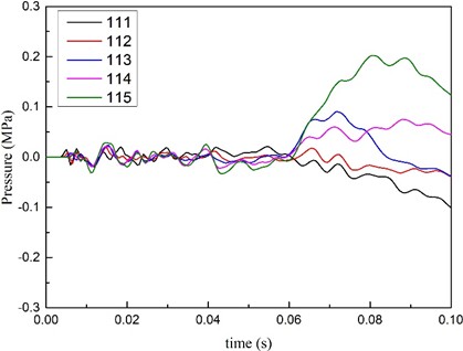
Fig. 11 details the time-dependent curves of the impact pressure on the key points of the stairway in this study’s model. It can be seen in the figure that, due to the stairs having a certain distance from the explosion source, the shock waves had reached the stairs in approximately 0.06 seconds. The impact pressure on the lower part of the stairs (for example, Points 111 and 112) was negative, and the impact pressure on the upper part (for example, Points 113, 114, and 115) was observed to be positive. Therefore, it could be seen that the stairs were prone to shear failure during the damage process. However, it was found that at Point 115, where the shock waves had arrived the latest, a maximum impact pressure was observed. In fact, the impact pressure had reached the maximum at 0.08 seconds after the explosion, and then gradually began to decrease after experiencing two obvious peaks.
Fig. 10Distribution of observation points on subway stairways
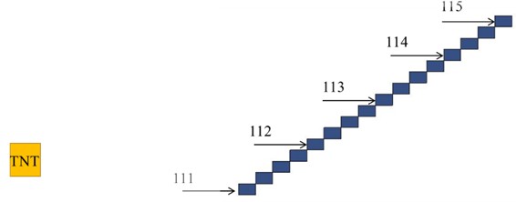
Fig. 11Curve of impact pressure on key points of subway stairways with time
3.3. Analysis of the pressure variations of station hallway flooring subjected to shock waves
The station hallway area was located above the explosion source in this study’s model, which could result in secondary injuries in cases of real damage situations, such as personnel experiencing falling injuries. This study further investigated the changes in impact pressure of the subway station hallway flooring under the conditions of a TNT explosion event in the subway station platform region. As illustrated in Fig. 12, observational points were selected in the horizontal and longitudinal directions, respectively, and were also in turn expanded around the explosion source.
Fig. 12Distribution of observation points on the station hallway flooring

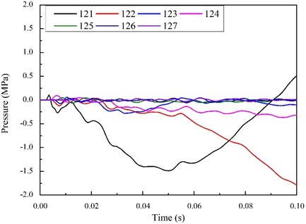
Fig. 13 shows the time-dependent curves of the impact pressure on the observational points of the station hallway floor. It was found that the impact pressure of observational Point 121, which was located closest to the explosion source, decreased with time, and had then gradually increased after reaching a peak value. The impact pressure levels of observational Points 125 to 127, which were located slightly away from the explosion source, were found to change only minimally.
Fig. 13Time curve of impact pressure on observation points of station hallway flooring
3.4. Analysis of the pressure variations of the platform flooring subjected to shock waves
The story in which the platform was located was under the explosion source. The platform flooring essentially had the smallest linear distance away from the explosion source, at only 1.6 m. As can be seen in Fig. 14, two rows of monitoring points were arranged on the upper layer of the platform flooring for the purpose of analyzing the propagation law of the explosion shock waves on the platform flooring in the case of a TNT explosion event.
Fig. 14Distribution of observation points on platform flooring

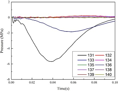
Fig. 15 shows the time-dependent curves of the impact pressure on the observational points located on the platform floor. It can be seen from the figure that the points with the maximum changes were Points 131 and 136. That is to say, the two points closest to the explosion source. The impact pressure was found to first increase, and then gradually decrease, reaching maximum values at 0.04 seconds and 0.06 seconds after the explosion occurred, respectively.
Fig. 15Curve of impact pressure at observation point of platform flooring with time
4. Analysis of the damage status of the subway structures
During the designing and construction of subway structures, the influencing effects of potential explosions should be fully considered. In addition, the protection measures for key structural parts should be strengthened. In previous sections of this study, the propagation law of the explosion waves when explosions occur in the subways was analyzed. This study’s further analysis results regarding the impacts of explosions on each key part of a subway structure were detailed in this section. Fig. 16 shows the overall changes before and after the explosion event. Due to the small deformations prior to and after the explosion when compared with the overall size, it was found to be difficult to determine the differences using only static pictures. However, it could be seen in the dynamic pictures that the areas A, B, and C had undergone significant changes, respectively. For example, in regard to Area A, which was located above the explosion source on the station hall floor, upward bending deformations had occurred. Meanwhile, in Area B, which was located in the platform floor under the explosion source, downward bending deformations were identified. Area C was the staircase area, in which deformations had occurred in the direction of shock wave propagation. It was found that when compared with the other three mechanisms, the columns had experienced no obvious deformations due to their large structural sizes. In following sections of this study, the structural characteristics of each key part were separately analyzed in order to identify the weakness of each structure.
Fig. 16Comparison of structural deformation before and after explosion
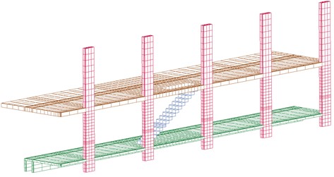
a) Overall state at 0 s
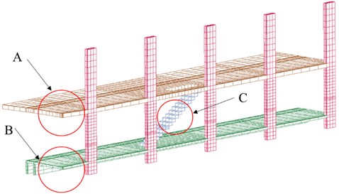
b) Overall state at 0.1 s
4.1. Analysis of the damage states of the support columns subjected to shock waves
As mentioned above, the impacts of the shock waves on the columns located adjacent to the source were the greatest. The areas with the greatest changes also occurred on the same columns. The column located nearest to the explosion source was selected for further analysis in this investigation. It has been found that for solid brittle structures, such as concrete, rock, cast iron, and so on, the first principal stress or equivalent stress are generally the items which should be checked according to the first and second strength theory. Fig. 17 shows the equivalent stress nephogram of the nearest column with time. In the figure, the circled parts represent the areas where the stress was concentrated at each moment. The maximum equivalent tensile stress of the column was determined to be 3.244 MPa, which was slightly higher than the tensile limit, and there were fewer areas. The maximum equivalent compressive stress was 8.499 MPa, which was less than the compressive limit. Therefore, when the 16.3 kg TNT exploded in the middle of the station in this study’s model, the column damage had not been serious, which ensured its working capacity.
Fig. 17Equivalent stress nephogram of support columns changing with time
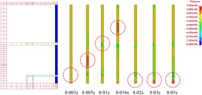
Fig. 18Z-direction displacement nephogram of support columns with time
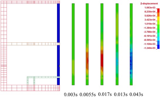
Fig. 19Displacement history curve of center point under support columns
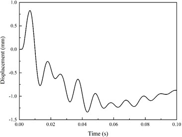
The center nodes of the lower part were selected in order to draw a displacement nephogram, as shown in Fig. 19. When the explosion shock wave reached the observation points, the pressure quickly reached its maximum value in the direction of shock wave propagation. Then, after the shock waves passed through the column, the column first recovered, then reached the maximum value in the opposite direction, and finally fluctuated around the maximum value.
Wang Wei theorized the reinforced concrete member equivalent to a single-degree-of-freedom (SDOF), and the equivalent single-degree-of-freedom (SDOF) was then simplified the motion of the continuum structure to a one-dimensional motion in the characteristic direction. In this study’s analysis process, the symmetric load and deflection were assumed, and the bearing angle was determined by the ratio of the calculated peak deflection to the half-span length /2, as indicated in the following equation:
In addition, the damage level was determined using the manual Structures to Resist the Effects of Accidental Explosions (TM5-1300), in which 0° 2° indicates mild damage; 2° 5° indicates moderate damage; and 5° 12° indicates severe damage. The maximum displacement of the column was determined to be 1.34 mm, and the calculated value was 0.14 °. Therefore, only mild damages had occurred.
4.2. Damage state analysis of the stairway subjected to shock waves
In this study’s model, the stairs were located far from the explosion source, and the shock wave reached the area in approximately 0.05 seconds. Fig. 20 shows the variations in the equivalent stress nephogram of the stairs with time following the shock wave arrival at the 0.05-second point. It can be seen in the figure that the maximum equivalent stress was 0.69 MPa, which is far less than the limit value. The shock waves first reached the 1st and 6th steps, and the position with the highest stress concentration was the 6th step. The height of the first step was 1.7 m from the platform floor, which was close to the height of the explosion source.
Fig. 20Equivalent stress nephogram of stairway changing with time
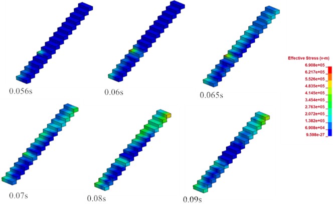
It was observed that the stairway area experienced higher stress concentrations at the junctions of the stairs with the platform, and also where the station hallway joined the stairway area, respectively. Since those positions were inlaid with the station hallway and platform story positions, the displacement was 0. Consequently, mainly only the displacement changes of the position of the 6th step were considered in this study.
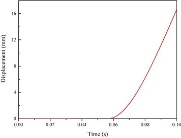
In accordance with the analysis results of the time history curves of the explosion shock wave direction in the stairway region, it was confirmed that the displacement deformations of the 6th step had been the largest. Fig. 21 shows the displacement history curves of the 6th step. It can be seen in the figure that displacement values gradually increased from the 0.06-second point, with the maximum value reaching 16.83 mm. In addition, a gradual upward trend could be observed. It was found that although the stress values of stairway area were less than the limit stress due to the large distance from the explosion source, the stress could still easily cause the stairs to collapse due to dislocation, since the structural characteristics of the stairs adopted a staggered arrangement for each step. Therefore, explosion-proof designs for stairways in subway stations should be considered in future designs.
Fig. 21Section 6 step displacement history curve
4.3. Analysis on the damage states of subway station hallway floors subjected to shock waves
In this study’s model, the subway station hallway floors were located above the explosion source. It was found that when the station story where the hallway was located experience the impacts of the explosion, collapsing had occurred. Such damages could potentially cause falling injuries to personnel in the station hallway area, as well as injuries to personnel on the platform story due to falling objects. Therefore, the ability of a station hallway story to withstand explosion shock waves is very important.
Fig. 22Time dependent equivalent stress nephogram of station hallway floors
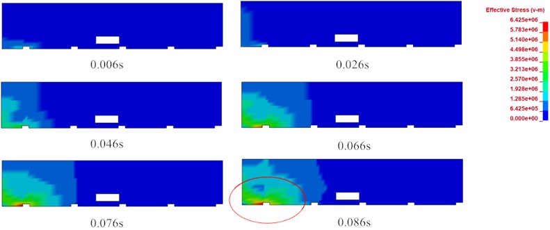
Fig. 22 shows the equivalent stress nephogram of the station hallway flooring over time. It can be seen in the figure that when the explosion occurred, the highest stress concentrations of the subway station hallway area were mainly located above the explosion source and had expanded with time. However, the maximum stress concentration point was not located directly above the explosion source, but at the junction between the station hallway and the column nearest to the explosion source. Therefore, it was confirmed that that subway station hallway area and the columns were important components of the subway structure. Based this study’s modelling results, it was recommended that during future subway design processes, the junctions between hallway areas and columns should be carefully considered. The maximum equivalent stress of station hallway area was 6.425 MPa in this study, which was greater than its limit value. Therefore, it was estimated that the area would potentially experience major damages.
Fig. 23Time relationship of subway station hallway floors displacement

a) Cloud chart of maximum displacement change in direction of explosion impact in subway station hallway floors
b) A. B displacement time history curve
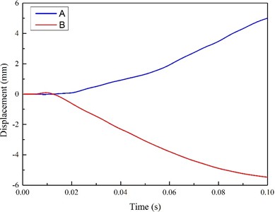
Fig. 23(a) details the nephogram of the maximum displacement change in the direction of explosion shock waves in the region of the station hallway. The two points with the largest deformations were selected in the figure for the purpose of estimating the displacement history curves, as shown in Fig. 23(b). In the figure, it can be seen that Point A bulges upward along the direction of the explosion shock waves, with a maximum value of 6.466 mm. Meanwhile, Point B displays a downward trend along the direction of explosion shock waves, with a maximum value of 5.354 mm.
4.4. Analysis of the damage states of the platform flooring subjected to shock waves
The story in which the platform was located was below the source at the height of 1.1 m. In the event of a platform collapse, people may experience injuries due to falls during the evacuation process, possibly resulting in a stampede. Fig. 24 shows the equivalent stress nephogram of the platform area when the stress concentrations reached the maximum. It can be seen in the figure that the areas with the highest stress concentrations on the platform story were similar to those of the station hallway story. However, due to the smaller distance from the explosion source, the maximum stress value was 14.35 MPa, and the resulting damage area was larger.
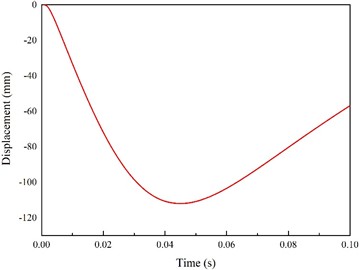
Fig. 25 details the displacement history curves at the maximum displacement locations of platform story (for example, the area directly above the explosion source). It was seen in the model results that due to the smaller distance from the explosion source, the displacement values had reached a maximum value of 112.8 mm at 0.04 seconds. Therefore, it was considered that the area under the explosion source would collapse.
Fig. 24Equivalent force nephogram of platform flooring

Fig. 25Displacement history curve at maximum displacement of platform flooring
5. Conclusions
In this study, a typical two-story two-span subway station structure was selected for analysis based on investigations and surveys of domestic underground subway stations. The propagation law of the explosion shock waves in a subway station structure under the condition of a 16.3 kg TNT explosion in the platform story region an underground station was examined. In addition, the potential damages caused by explosive shock waves to underground subway station structures were analyzed using a modelling process with the numerical simulation software LS-DYNA. The main research results obtained in this study were as follows:
1) In this study’s model, when the explosion source exploded in the center of the station platform story, shock waves were diffused to both sides. Then, due to the counterattack and superposition effects on the shock waves of the subway station walls and structures, it was found that the shock wave intensity first increased and decreased with time. However, the overall value of the shock waves had increased with time.
2) This study found that within the station structure, the maximum displacement of the column nearest the explosion source caused by the shock waves of the 16.3 kg TNT explosion was 1.34 mm, and this was considered to be enough to ensure its safety. However, the maximum displacement of the stairway area had reached 16.83 mm, which had the potential to cause the stairs to become dislocated and collapse. The maximum displacement of the station hallway floor area was determined to be 5.354 mm, with the junction position with the column nearest the explosion source at risk of becoming damaged. The maximum displacement of platform story was 112.8 mm, which would result in the platform story collapsing. Therefore, it was concluded that in the case of a 16.3 kg TNT explosion, the general structure of the station could ensure its overall integrity, but local areas would become significantly damaged or collapse.
3) It was observed in this study’s modelling process that stress concentrations had easily formed at the junctions of the columns and the station hallway and platform regions. Therefore, in future subway design processes, it is recommended that the joint positions of columns with hallway and platform zones should be strengthened.
4) It was found in this study that even if stairways were located far from an explosive source, the possibility of collapse remained high. Therefore, in order to not negatively affect the evacuation of personnel during an explosion situation, the stairway areas of subway stations should be strengthened, or it should be forbidden to use stairs for the evacuation of personnel.
The response of each important part of the subway station after explosion is preliminarily analyzed, and the mechanical response of each part under explosion is obtained in this paper. In future research, we will conduct further research and analysis on the parts with greater impact, such as different materials, different equivalent energy, different explosion parts, etc., to provide the basis for the design of disaster prevention and safety performance improvement of subway stations.
References
-
J. Henrych, The Dynamics of Explosion and Its Use. New York: Elsevier, 1979.
-
G. C. Mays and P. D. Smith, Blast Effects on Buildings. NewYork: Thomas Telford, 1995.
-
P. D. Smith, G. C. Mays, T. A. Rose, K. G. Teo, and B. J. Roberts, “Small scale models of complex geometry for blast overpressure assessment,” International Journal of Impact Engineering, Vol. 12, No. 3, pp. 345–360, Jan. 1992, https://doi.org/10.1016/0734-743x(92)90112-7
-
B. Janovsky, P. Selesovsky, J. Horkel, and L. Vejsa, “Vented confined explosions in Stramberk experimental mine and AutoReaGas simulation,” Journal of Loss Prevention in the Process Industries, Vol. 19, No. 2-3, pp. 280–287, Mar. 2006, https://doi.org/10.1016/j.jlp.2005.06.038
-
A. C. van den Berg and J. Weerheijm, “Blast phenomena in urban tunnel systems,” Journal of Loss Prevention in the Process Industries, Vol. 19, No. 6, pp. 598–603, Nov. 2006, https://doi.org/10.1016/j.jlp.2006.03.001
-
M. A. Mat Norman, M. R. Mohd Razean, M. H. Mohd Rosaidi, M. S. Ismail, and J. Mahmud, “Effect of fibre volume on the natural frequencies of laminated composite plate,” Materials Today: Proceedings, Vol. 75, pp. 133–139, Jan. 2023, https://doi.org/10.1016/j.matpr.2022.10.245
-
M. S. Ismail, O. Ifayefunmi, and A. H. Mazli, “Combined stability of cone-cylinder transition subjected to axial compression and external pressure,” Thin-Walled Structures, Vol. 157, p. 107102, Dec. 2020, https://doi.org/10.1016/j.tws.2020.107102
-
M. S. Ismail and J. Mahmud, “Buckling and postbuckling analysis of stiffened cylindrical shells subjected to axial compression and external pressure,” in Lecture Notes in Mechanical Engineering, Singapore: Springer Nature Singapore, 2024, pp. 519–529, https://doi.org/10.1007/978-981-97-0169-8_42
-
G. Giannopoulos, M. Larcher, F. Casadei, and G. Solomos, “Risk assessment of the fatality due to explosion in land mass transport infrastructure by fast transient dynamic analysis,” Journal of Hazardous Materials, Vol. 173, No. 1-3, pp. 401–408, Jan. 2010, https://doi.org/10.1016/j.jhazmat.2009.08.096
-
Q. S. Yan, T. Y. Chen, and W. Z. Liao, “Comparison of numerical analysis loading methods of RC columns under near-field explosion,” Journal of Beijing University of Technology, Vol. 46, No. 2, pp. 154–161, 2020, https://doi.org/10.11936/bjutxb2018070034
-
E. Akhlaghi, “Numerical simulation of air shock wave propagation effects in reinforced concrete columns,” Journal of Modeling and Optimization, Vol. 12, No. 1, pp. 12–22, Jun. 2020, https://doi.org/10.32732/jmo.2020.12.1.12
-
A. Shishegaran, M. R. Ghasemi, and H. Varaee, “Performance of a novel bent-up bars system not interacting with concrete,” Frontiers of Structural and Civil Engineering, Vol. 13, No. 6, pp. 1301–1315, Oct. 2019, https://doi.org/10.1007/s11709-019-0552-4
-
X. X. Zhang et al., “Numerical simulation studies on effects of explosion impact load on underground mine seal,” Mining, Metallurgy and Exploration, Vol. 37, pp. 665–680, Apr. 2020, https://doi.org/10.1007/s42461-00143-2
-
X. Zhang, J. Cheng, and C. Shi, “Damage assessment for underground brick seal under explosion impact load,” Arabian Journal of Geosciences, Vol. 14, No. 5, Feb. 2021, https://doi.org/10.1007/s12517-021-06681-8
-
K. S. Luo, Y. Wang, Y. T. Zhao, and L. K. Huang, “Numerical simulation of subway tunnel under ground explosion load,” Journal of PLA University of science and Technology, Vol. 8, No. 6, pp. 674–679, 2007, https://doi.org/10.7666/j.issn.1009-3443.20070621
-
M. Buonsanti and G. Leonardi, “3-D simulation of tunnel structures under blast loading,” Archives of Civil and Mechanical Engineering, Vol. 13, No. 1, pp. 128–134, Mar. 2013, https://doi.org/10.1016/j.acme.2012.09.002
-
O. Pennetier, M. William-Louis, and A. Langlet, “Numerical and reduced-scale experimental investigation of blast wave shape in underground transportation infrastructure,” Process Safety and Environmental Protection, Vol. 94, pp. 96–104, Mar. 2015, https://doi.org/10.1016/j.psep.2015.01.002
-
W. Z. Liao and X. L. Du, “Study on propagation law of explosion wave in subway station,” Journal of disaster prevention and Mitigation Engineering, Vol. 30, No. 5, pp. 538–543, 2010, https://doi.org/10.3969/j.issn.1672-2132.2010.05.011
-
S. S. Qu and Z. X. Li, “Propagation law of explosion wave and overpressure load in subway station,” Engineering Mechanics, Vol. 27, No. 9, Sep. 2010.
-
S. Q. Li, X. Li, and G. Y. Wu, “Numerical simulation of blast wave propagation in subway station,” Journal of vibration and shock, Vol. 32, No. 7, pp. 175–178, 2013, https://doi.org/10.3969/j.issn.1000-3835.2013.07.035
-
W. S. Hu, “Numerical analysis of explosion shock propagation in subway station,” Science and Technology Vision, Vol. 2016, No. 5, pp. 116–117, 2016, https://doi.org/10.3969/j.issn.2095-2457.2016.05.083
-
Z. Hu, N. Jiang, Y. Zhang, Y. Xia, and C. Zhou, “Propagation of shock wave and structure dynamic response of explosion in a subway station: a case study of Wuhan subway station,” Journal of Vibroengineering, Vol. 22, No. 6, pp. 1453–1469, Sep. 2020, https://doi.org/10.21595/jve.2020.21298
-
K. Mahmadi, N. Aquelet, M. Souli, and J. Gabrys, “ALE multi-material formulation of high explosive detonation using LS-DYNA3D,” in ASME 2002 Pressure Vessels and Piping Conference, pp. 111–119, Jan. 2002, https://doi.org/10.1115/pvp2002-1468
-
C. R. Welch and C. E. Joachim, “In-tunnel airblast engineering model for internal and external detonations,” in 8th International Symposium on Interaction of the Effects of Munitions with Structures, 1997.
-
Q. S. Yan, J. B. Liu, and J. Wu, “Estimation of casualty areas in subway station subjected to terrorist bomb,” (in Chinese), Engineering Mechanics, Vol. 29, No. 2, pp. 81–88, Feb. 2012.
About this article
This work is financially supported by the National Key R&D Program of China (No. 2023YFC3010601).
The datasets generated during and/or analyzed during the current study are available from the corresponding author on reasonable request.
Xixi Zhang conceived the original idea and wrote the manuscript. Dan Wang jointly supervised the study. Kaiqun Zhang processed and analyzed the data.
The authors declare that they have no conflict of interest.
