Abstract
Taking a shear wall structure in a high-intensity area of 20 floors as an example, the seismic reduction scheme of the structure was determined, and the Etabs software was used to conduct time history analysis on the seismic and non-seismic structures. The floor shear force, overturning moment, and short-term surface pressure of the isolation support were obtained. The results showed that under frequent earthquake action, the average maximum floor shear force in the direction of the isolated upper structure was only about 28 % of that of the non-isolated structure. The maximum inter story shear ratio was 0.34, and the maximum floor shear force in the direction was only about 25 % of that of the non-isolated structure. The maximum inter story shear ratio was 0.31. The average maximum overturning moment of the upper structure in the direction after isolation is about 30 % of that of the non-isolated structure. The maximum overturning moment ratio is 0.36, and the average overturning moment of the maximum floor in the direction is about 22 % of that of the non-isolated structure. The maximum overturning moment ratio is 0.26. Under rare earthquake action, the maximum inter story displacement angles in the and directions of each floor of the seismic isolation structure are 1/302 and 1/446, respectively. The maximum surface pressure value of the isolation bearing under rare earthquake is 28.9 MPa, the minimum surface pressure value is 5.58 MPa, and the maximum displacement is 579 mm, which meets the requirements of the specifications. Overall, the seismic performance of the seismic isolation structure is good, and the isolation scheme is feasible.
1. Introduction
Shear wall structure, as a common and effective lateral force resisting system, is widely used in high-rise buildings. However, earthquakes, an unpredictable natural disaster, always pose a huge threat to building structures. Traditional shear wall design mainly focuses on enhancing the stiffness and strength of the structure to resist seismic forces, while isolation design introduces a new concept, which is to set isolation layers between the structure and the foundation, isolate and consume seismic energy through the flexible deformation of the isolation layers, thereby reducing the direct impact of earthquakes on the structure. In isolation design, multiple isolation lines are usually set up to increase the redundancy and ductility of the structure. Shear wall isolation, as an innovative structural seismic strategy, aims to effectively isolate the transmission of seismic energy by installing isolation devices, thereby significantly reducing the seismic effects on the upper structure [1-4]. The application of this technology, especially in high-intensity areas, not only provides new ideas and methods for seismic design of shear wall structures, but also has the potential to play a key role in ensuring the safety of people's lives and property and reducing earthquake disaster losses.
In recent years, scholars at home and abroad have conducted relevant research on shear wall isolation technology and achieved certain results. Calugaru et al. [5] compared the seismic response of a 20 story reinforced concrete shear wall structure located in a near fault area under isolation and non-isolation conditions, and the results showed that the isolation structure performed better than the non-isolation structure. Xing et al. [6] used a high-rise reinforced concrete shear wall structure in Xichang City as an example to conduct seismic isolation design and seismic performance analysis. The results showed that the maximum inter story shear force and overturning moment damping coefficient of the structure under moderate earthquake action was 0.24, which significantly reduced the seismic response of non-isolated structures. Under rare earthquakes, the surface pressure and horizontal displacement of the isolation bearings can meet the requirements of the code. In addition, a rare earthquake dynamic elastoplastic time history analysis was conducted, and the results showed that the structure can meet the seismic fortification goal of “not collapsing in large earthquakes”. Xu et al. [7] applied seismic isolation technology to a high-rise shear wall structure in Tangshan City, and established finite element models for both non isolated and isolated structures, and conducted nonlinear time history analysis. The results showed that the eccentricity of the isolation layer and the wind resistance design met the requirements of the specifications. Under frequent earthquake action, the horizontal seismic reduction coefficient of the isolation structure is not greater than 0.38, and the maximum inter story displacement angle of the upper structure is less than 1/800; Under rare earthquake conditions, the viscous damper effectively controls the deformation of the isolation layer, and no tension occurs in any bearings. The seismic performance of the isolation structure is good, and the isolation scheme is feasible.
For traditional seismic resistant structures, the larger the cross-sectional size of the component, the greater its stiffness, and the increased seismic absorption, which not only causes material waste but also is detrimental to the safety of the structure under rare earthquake conditions. After adopting seismic isolation technology, the seismic effect absorbed by the upper structure has been effectively reduced, and the building's usable space has been increased. In addition, the reasonable arrangement of shock-absorbing bearings can improve the seismic performance of the structure, and the upper structure can be designed with a reduction of one or half degrees. In order to better apply seismic isolation technology in high-intensity areas, this paper takes a high-rise reinforced concrete shear wall structure in high-intensity areas as the research object, analyzes the seismic performance of the high-rise shear wall system in high-intensity areas after adopting seismic isolation technology, and provides a basis and reference for seismic isolation of shear walls in high-intensity areas.
2. Overview of engineering cases
This project case is a shear wall bottom isolation structure. The building has 20 floors above ground, a height of 60.3 meters, a width of 27.3 meters, and a height to width ratio of 2.21. The isolation layer is set on the first floor, with a height of 3.60. The seismic grouping is designed as the third group, with a construction site category of Class II, ground roughness of Class B, and a site characteristic period of 0.45 s. The seismic fortification intensity is 9 degrees, and the designed basic seismic acceleration value is 0.4 g. The building has a service life of 50 years.
3. Layout plan of seismic isolation bearings
A seismic isolation layer is installed on the first floor of this building, using a total of 31 lead rubber bearings LRB1200. The bearing parameters are shown in Table 1, A seismic isolation layer is installed on the first floor of this building, using a total of 31 lead rubber bearings LRB1200. The bearing parameters are shown in Table 1, where the vertical stiffness is calculated according to Eq. (1) and the equivalent damping ratio is calculated according to Eq. (2):
where is the modified elastic modulus obtained by considering the influence of volume change; is the thickness of each rubber layer:
where is the area of work done by the restoring force; is the area of damping energy dissipation.
Table 1Parameters of seismic isolation bearings
Characteristic | LRB1200 |
Effective diameter (mm) | 1200 |
Rubber shear modulus (N/mm2) | 0.5 |
Pre yield stiffness (kN/m) | 31000 |
Stiffness after yielding (kN/m) | 2440 |
100 % equivalent stiffness (kN/m) | 3440 |
Equivalent damping ratio (Heq)% | 19 |
Vertical stiffness (kN/mm) | 5800 |
Yield force (kN) | 232 |
The layout plan of the seismic isolation bearings is shown in Fig. 1. The yield to weight ratio is 4.21 %, and the eccentricity between the rigid position of the seismic isolation layer in the and directions and the overall structural center of gravity is 0.0102 % and 2 %, respectively, which is less than 3 %. The maximum compressive strength of the support under the representative value of gravity load is 9.2 MPa, which is lower than the compressive stress limit of Class C fortified buildings of 15 MPa and meets the requirements of the specifications.
Fig. 1Layout plan of seismic isolation layer bearings
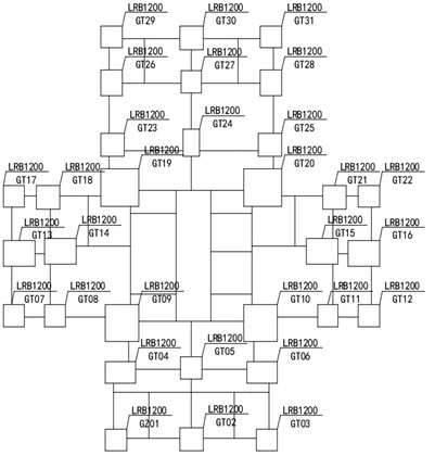
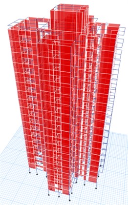
Fig. 2Three dimensional model
To ensure the effectiveness of the wind resistance device and the good reset performance of the isolation device under multiple earthquakes, the isolation layer should have sufficient horizontal bearing capacity and elastic recovery capacity. The standard horizontal sheer force of the isolation layer under wind load is 988 kN in the direction and 1210 kN in the direction. The design horizontal shear force is 1383 kN in the direction and 1694 kN in the direction, which is less than the yield force of 7192 kN of each support of the isolation structure and meets the design requirements.
4. Structural seismic isolation analysis
4.1. Establishment of structural model
The finite element calculation model of the isolation structure was established using Etabs, as shown in Fig. 2. This project case intends to use 5 seismic waves, as shown in Table 2. The upper structure and isolation layer are both modeled in 3D, while the beams, columns, and floor slabs of the upper structure only consider elasticity. The isolation bearings are calculated using a nonlinear model. In response to the different tensile and compressive stiffness of isolation bearings, ETABS software uses Rubber Isolator elements and Gap elements in parallel. The mechanical behavior of gap elements is shown in Eq. (3):
where is the vertical stiffness of the Gap element; is the relative displacement of the node (positive value for stretching and negative value for compression); is the width of the seam (zero or positive value).
Table 2Basic parameters of seismic waves
Time schedule abbreviation | Full name of schedule | Peak acceleration (cm/s²) | Seismic fortification adopts the maximum seismic acceleration value (cm/s²) | Maximum earthquake acceleration during rare earthquakes (cm/s²) |
Artificial wave 1 | REN11 | 100 | 400×1.5 | 620×1.5 |
Artificial wave 1 | REN12 | 100 | 400×1.5 | 620×1.5 |
Natural wave 1 | ELCENTRO | 100 | 400×1.5 | 620×1.5 |
Natural wave 2 | CPC_TOPANGA CANYON_16_nort | 100 | 400×1.5 | 620×1.5 |
Natural wave3 | SFERNPEL090.txt | 100 | 400×1.5 | 620×1.5 |
4.2. Seismic response analysis under fortification intensity
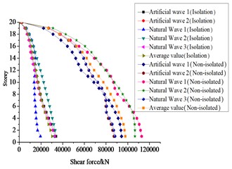
Under seismic fortification intensity, the envelope diagrams of inter story shear force and overturning moment of the structure are shown in Fig. 3 and Fig. 4, respectively. Comparing the seismic responses before and after isolation, it can be seen that the average maximum floor shear force in the direction of the upper structure after isolation is only about 28 % of that of the non-isolated structure. Among them, the maximum inter story shear force ratio is 0.34, and the maximum floor shear force in the direction is only about 25 % of that of the non-isolated structure. The maximum inter story shear force ratio is 0.31. The average maximum overturning moment of the upper structure in the direction after isolation is only about 30 % of that of the non-isolated structure, with a maximum overturning moment ratio of 0.36. The average maximum overturning moment of the upper structure in the direction is only about 22 % of that of the non-isolated structure, with a maximum overturning moment ratio of 0.26. According to the specifications, the maximum horizontal seismic impact coefficient after isolation is 0.203. After comprehensive consideration, the maximum horizontal seismic influence coefficient of the upper structure after seismic isolation design is 0.203 or reduced by 0.5 degrees according to the seismic intensity.
Fig. 3Envelope diagram of interlayer shear force under seismic fortification intensity
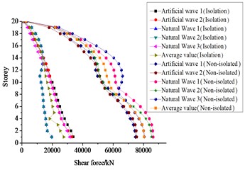
a) Envelope diagram of interlayer shear force in direction
b) Envelope diagram of interlayer shear force in direction
Fig. 4Envelope diagram of overturning moment under seismic fortification intensity
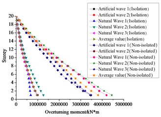
a) Envelope diagram of overturning moment in direction
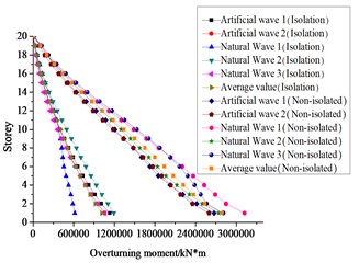
b) Envelope diagram of overturning moment in direction
4.3. Seismic response analysis under rare earthquakes
Under the rare earthquake of 9 degrees (0.40 g), the displacement angles between the and layers of the structure are shown in Fig. 5, and the maximum horizontal displacement of the isolation layer of the isolation structure is shown in Table 3.
Fig. 5Inter story displacement angle of structures under rare earthquakes
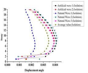
a) Inter story displacement angle in the direction
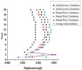
b) Inter story displacement angle in the direction
From Fig. 5, it can be seen that the maximum inter story displacement angles in the and directions of each floor of the structure are 1/302 and 1/446, respectively, both of which are less than the inter story displacement angle limit of 1/120. The results indicate that the structure meets the requirements of the inter story elastic-plastic displacement angle limit and meets the seismic fortification goal of “not collapsing in large earthquakes”, which also means that the structure will not overturn. From Table 3, it can be seen that under rare earthquake conditions, the maximum displacement of the isolation layer meets the requirements of the maximum allowable displacement of the support.
Table 3Maximum horizontal displacement of isolation layer
Direction | Maximum horizontal displacement | Maximum allowable value | |||||
Artificial wave 1 | Artificial wave 2 | Natural wave 1 | Natural wave 2 | Natural wave 3 | Average value | ||
direction | 650 | 640 | 396 | 550 | 611 | 569 | 660 |
direction | 644 | 646 | 405 | 570 | 629 | 579 | 660 |
4.4. Short term surface pressure analysis of seismic isolation bearings
Under rare earthquake conditions, the maximum surface pressure value in the direction of the isolation bearing appears in the GZ1 bearing at 26.6 MPa, the maximum surface pressure value in the direction appears in the GZ10 bearing at 28.9 MPa, the extreme surface pressure value in the direction appears in the GZ20 bearing at 5.67 MPa, and the extreme surface pressure value in the direction appears in the GZ19 bearing at 5.58 MPa. This indicates that the isolation bearing does not experience tensile stress under rare earthquake conditions, and the tensile stress of the isolation bearing meets the specification requirements.
5. Conclusions
1) This project adopts seismic isolation design, and the damping coefficient can be controlled within 0.36. The maximum horizontal seismic influence coefficient of the upper structure is 0.203 or reduced by 0.5 degrees according to the seismic intensity.
2) The maximum inter story displacement angles in the and directions after seismic isolation of the structure are 1/302 and 1/446, respectively, meeting the requirements of inter story elastic-plastic displacement angle limit. The maximum displacement of the isolation layer meets the requirements of the maximum allowable displacement of the support.
3) The eccentricity and wind resistance design of the isolation layer of the structure meet the requirements of the specifications. The maximum surface pressure value of the isolation bearings in rare earthquakes is 28.9 MPa, the minimum surface pressure value is 5.58 MPa, and the maximum displacement is 579 mm, which meets the requirements of the specifications. This indicates that the isolation structure design of this project is reasonable and the arrangement of the isolation bearings is reasonable.
References
-
R. Sun and Y. Qi, “Research on the Limit value of aspect ratio of the frame and shear wall isolation structure of a high-rise building,” South China journal of seismology, Vol. 41, No. 1, pp. 137–145, 2021.
-
Z. Chen, Z. Cai, and W. Chen, “Research on calculation methods for base-isolated shear wall structure with bending scissor characteristics,” Building Structure, Vol. 54, No. 9, pp. 134–138, 2024.
-
S. Yu and X. Liu, “Seismic response analysis of large chassis frame supported shear wall isolated structure in high intensity region,” Guangdong Building Materials, Vol. 40, No. 7, pp. 60–63, 2024.
-
L. Shufeng and Z. Di, “Research on the mechanical behavior of high-strength bolted joints between prefabricated concrete beams and columns,” Mechanics of Advanced Materials and Structures, Vol. 31, No. 8, pp. 1832–1846, Apr. 2024, https://doi.org/10.1080/15376494.2022.2143971
-
V. Calugaru and M. Panagiotou, “Seismic response of 20-story base-isolated and fixed – base reinforced concrete structural wall buildings at a near-fault site,” Earthquake Engineering and Structural Dynamics, Vol. 43, No. 6, pp. 927–948, 2014.
-
J. H. Xing, D. D. He, L. G. Bu, Q. S. Miao, M. Lu, and Z. Y. Huang, “Design and analysis of the isolated bearings for a high – rise shear wall structure in Xichang City,” China Earthquake Engineering Journal, Vol. 41, No. 2, pp. 332–339, 2019.
-
W. Z. Xu, S. G. Wang, W. Q. Liu, and D. S. Du, “Isolation design and analysis of seismic performance of a high-rise shear wall structure,” Building Structure, Vol. 47, No. S2, pp. 325–329, 2017.
About this article

The work was supported by Henan Province’s Department of Education through Grant No. 23A560023. The work was supported by the Department of Housing and Urban Rural Development of Henan Province through Grant No. K2123. The work was supported by the Department of Housing and Urban Rural Development of Henan Province through Grant No. HNJS-2022-K48.
The datasets generated during and/or analyzed during the current study are available from the corresponding author on reasonable request.
The authors declare that they have no conflict of interest.
