Abstract
In order to improve the safety of wind turbine, this paper takes the high-speed spur gear on output shaft in the transmission system of the wind turbine as the study object. The original signals of the gear in different fault states which obtained from the experimental platform decompose by the empirical mode decomposition method (EMD) and the variational mode decomposition method (VMD), respectively. Then the different gear fault types’ eigenvectors were built. Fuzzy neural network (FNN) is adopted to learn the fault types and eigenvector samples of gears, and then the fault types of gears are identified. It is found that the fault features decomposed by VMD method have reached a high accurate recognition rate point to the fact that VMD has good applicability in the fault recognition of gear in wind turbine.
Highlights
- In this paper, the high-speed spur gear on output shaft in the transmission system of the wind turbine was taken as the study object. The original signals of the high-speed spur gear in six different states were collected.
- The EMD and VMD decomposition method are used to decompose the original signals of spur gear in different fault states, and the eigenvectors are constructed.
- The FNN is adopted to learn fault types and eigenvector samples to identify fault types. It can be concluded that the VMD method is significantly better than the EMD method in terms of gear fault type identification.
1. Introduction
The installation location of wind turbines is remote and harsh with abundant wind resources, resulting in a high failure rate and high operation and maintenance costs. From the perspective of the downtime caused by a single fault of the wind turbine, the longest downtime caused by the fault of the transmission system, the main shaft and the main shaft bearing [1]. Gear is an important part of the wind turbine’s transmission system. Gear faults include fracture, pitting corrosion, wear and so on. Once the gear fails, if it cannot be maintained in time, it will lead to the fracture of the gear teeth, and the economic loss caused cannot be estimated [2]. To sum up, the accuracy of the fault type detection of the transmission system will count for much to wind turbine’s stability and life.
Scholars have done a lot of research of wind turbine’s transmission system. X. J. Luo et al. adopted the variational mode decomposition (VMD) and the local mean decomposition (LMD) to identify faults of the transmission system in wind turbine, and the founds show that VMD has a better performance than LMD [3]. X. L. An et al. proposed a bearing fault diagnosis method based on VMD and the singular value decomposition method (SVD) and found that the proposed method can effectively identify the fault type of wind turbine roller bearings [4]. W. X. Yang et al. found that the superiorities of the VMD over the EMD in multi-component signal decomposition and noise robustness of wind turbine's condition monitoring signals. [5]
In this paper, the original signal data of high-speed spur gear in the normal state, eccentricity fault, broken tooth fault, tooth missing fault, root wear fault, tooth surface wear fault are collected by the experimental platform. The EMD and VMD decomposition methods are used to construct the eigenvectors in different faults conditions, and the fault types are identified by the fuzzy neural networks method (FNN). It is found that the fault recognition accuracy of the eigenvector obtained by VMD decomposition method is better than that of EMD.
2. Research object
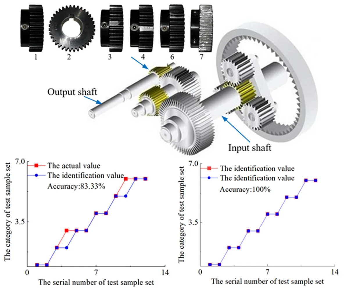
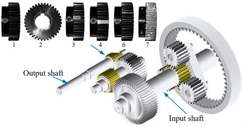
In this paper, the high-speed spur gear which links the output shaft in the transmission system of a 1.5 MW wind turbine is used as the research object. Its number of teeth is 36 and the modulus is 1. The three-dimensional model of the transmission system and the high-speed spur gear with different faults are shown in Fig. 1. As shown in Fig. 1, one end of the stroke shaft is connected with the wind wheel to collect wind energy, and the other end is connected with the planetary gear. The planetary gear increases the speed of the sun gear which is connected with the primary cylindrical gear. The primary cylindrical gear is meshed with the secondary cylindrical gear to drive the secondary gear to rotate. The pinion in the secondary gear is connected with the output shaft to finally complete the gear transmission.
Fig. 1Wind turbine drive system and high speed spur gears with different fault types: 1 –normal state; 2 –eccentricity fault; 3 –broken tooth fault; 4 –tooth missing fault; 5 –root wear fault; 6 –tooth surface wear fault
This paper uses the high-speed spur gear in the gearbox of wind turbine as the object of study. The experimental platform of the transmission system as shown in references [6], this article will not repeat High speed spur gear fault signal acquisition experiment through different fault high-speed spur gears installed in the gearbox for data acquisition. During the experiment, the sampling frequency was set at 5000 Hz, the sampling time was set at 1s, and the torque was applied at 22 N·M. the original signals of the high-speed spur gear in six different states, including normal state, eccentricity fault, broken tooth fault, tooth missing fault, root wear fault, tooth surface wear fault, were collected, and 10 groups of data were collected in each state.
3. Gear fault signal feature extraction of the drive system by EMD and VMD
3.1. Feature extraction of gear fault signal in transmission system by EMD
When using EMD method to decompose the signal, first determine the extreme point of the signal, fit the upper and lower envelopes through cubic spline curve, and calculate the average value , and then subtract the average value from the original signal to obtain the residual component . The formula is as follows:
Determine whether meets the requirements of the eigenfunction. The requirements of the eigenfunction are that the mean value of the upper and lower envelopes of the extreme points is 0 and the absolute value of the difference between the number of zeros of the signal and the number of extreme points is less than 1 [7, 8]. If not, will be used to replace of the above formula to continue the calculation, and continue to iterate in this way until the first satisfying the requirements of the eigenfunction is obtained. is the first eigenfunction IMF of signal .
Separate the first eigenfunction from the original signal:
The second eigenfunction can be obtained by repeating the above process with instead of the original signal . s to get the IMF of signal , repeat the above step until becomes a monotonic function or is less than a certain value, the decomposition is no longer carried out.
EMD signal decomposition method is like filtering a composite signal layer by layer, separating the high and low frequency signals in turn, and the separation process is adaptive, and there is no energy loss. However, due to the inevitable introduction of human interference in the fitting of cubic spline, the envelope mean value of the actual IMF component may not be zero. With the increase of “screening” times, the mean value of the envelope will be closer and closer to zero, and the error will be gradually amplified, making the original signal lose practical significance. Therefore, this paper selects the mean square deviation of two continuous residual components as the termination condition:
According to experience, if is taken as 0.2-0.3, it can ensure that the component has physical significance and avoid interference caused by excessive decomposition.
Adopted the energy ratio method to extract the IMF, then the signal component extracted by EMD. There are six operating states including normal state. Some results are shown in Table 1.
Table 1The partial fault feature vectors of the gear
Fault type | E1/E | E2/E | E3/E | E4/E | E5/E | E6/E | E7/E | E8/E |
Normal state | 0.421948 | 0.281404 | 0.093654 | 0.065078 | 0.039957 | 0.036219 | 0.043272 | 0.018468 |
Normal state | 0.431677 | 0.268314 | 0.091861 | 0.063007 | 0.043087 | 0.043661 | 0.043104 | 0.015287 |
Eccentricity fault | 0.478213 | 0.210197 | 0.114117 | 0.063592 | 0.045983 | 0.040005 | 0.032357 | 0.015535 |
Eccentricity fault | 0.447222 | 0.235960 | 0.119523 | 0.067678 | 0.044014 | 0.038805 | 0.031727 | 0.015070 |
Broken tooth fault | 0.451266 | 0.228876 | 0.114863 | 0.070436 | 0.048531 | 0.039104 | 0.027439 | 0.019486 |
Broken tooth fault | 0.463258 | 0.221837 | 0.103140 | 0.068328 | 0.045238 | 0.044793 | 0.031285 | 0.022121 |
Tooth missing fault | 0.437031 | 0.219139 | 0.144121 | 0.061009 | 0.038331 | 0.031268 | 0.041555 | 0.027547 |
Tooth missing fault | 0.482446 | 0.196651 | 0.146391 | 0.055639 | 0.033877 | 0.032658 | 0.040523 | 0.011816 |
Root wear fault | 0.443527 | 0.250698 | 0.080827 | 0.057076 | 0.034810 | 0.048929 | 0.062395 | 0.021738 |
Root wear fault | 0.441150 | 0.239928 | 0.088578 | 0.056251 | 0.035795 | 0.038330 | 0.080894 | 0.019076 |
Tooth surface wear fault | 0.409309 | 0.248608 | 0.132868 | 0.056343 | 0.075230 | 0.041273 | 0.029230 | 0.007136 |
Tooth surface wear fault | 0.421668 | 0.228529 | 0.150053 | 0.055432 | 0.061506 | 0.042899 | 0.026657 | 0.013256 |
3.2. Feature extraction of gear fault signal in transmission system by VMD
The VMD method assumes that the original signal is a number of signal components with their own central frequency band and bandwidth, and then turns the signal decomposition problem into a variational problem [9]. The constrained variational model of VMD is:
where is each modal function, , is the center frequency of each mode, .
By introducing the augmented Lagrange function in the above formula [10]:
where is penalty function, is augmented Lagrangian multiplier.
For all 0, update the functional:
Update functional :
For all 0, double lift:
where means noise. When the signal contains strong noise, make 0 to achieve better denoising effect.
The functional is updated repeatedly until the following iterative constraints are met:
For all 0 analytic signals, the single-sided spectrum only contains nonnegative frequencies.
Each modal signal is iterated continuously in the frequency domain, and the iteration is stopped when the conditions are met. Then the center of the estimated frequency band is continuously reestimated according to the new iterative signal until the error requirements are met.
Adopted the energy ratio method to extract IMF, then the signal component extracted by VMD. Some results are shown in Table 2.
4. Fault type identification based on FNN
The network composed of two or more fuzzy neurons is called fuzzy neural networks (FFN), which is the fusion of fuzzy logic and neural network. The general neuron model is:
where denotes the input of neuron, denotes the link weight corresponding to , is the threshold value of the neuron, is output, is the conversion function.
Table 2The partial fault feature vectors of the gear
Fault type | E1/E | E2/E | E3/E | E4/E |
Normal state | 0.069056269 | 0.076479214 | 0.472369922 | 0.382094596 |
Normal state | 0.07351386 | 0.078250304 | 0.439528542 | 0.408707295 |
Eccentricity fault | 0.071219562 | 0.196108854 | 0.441261576 | 0.291410007 |
Eccentricity fault | 0.077397255 | 0.180720165 | 0.425303775 | 0.316578805 |
Broken tooth fault | 0.054700383 | 0.149938827 | 0.226052605 | 0.569308184 |
Broken tooth fault | 0.054370649 | 0.141558203 | 0.236331133 | 0.567740015 |
Tooth missing fault | 0.079052757 | 0.195995129 | 0.204101346 | 0.520850768 |
Tooth missing fault | 0.086850606 | 0.199743622 | 0.245669344 | 0.467736428 |
Root wear fault | 0.096864506 | 0.152294874 | 0.360502782 | 0.390337838 |
Root wear fault | 0.099500908 | 0.147678385 | 0.363703502 | 0.389117206 |
Tooth surface wear fault | 0.120019457 | 0.19256755 | 0.292426305 | 0.394986688 |
Tooth surface wear fault | 0.111690286 | 0.184365777 | 0.270145946 | 0.433797991 |
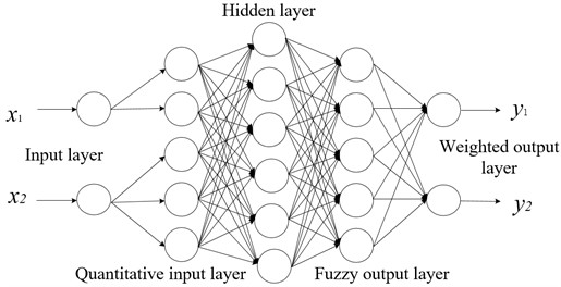
The structure diagram of the most common FNN model is shown in Fig. 2. As shown in Fig. 2, the basic structure has five layers. The input layer does not process data, but only fuzziness the original data. The quantization input layer quantifies the fuzzy quantity of the input layer. The hidden layer of BP network, which maps the input fuzzy variables of the second layer to the fuzzy output variables. The fuzzy output layer outputs the fuzzy variables obtained from the hidden layer. The weighted output layer weights the fuzzy output variables.
Fig. 2A schematic diagram of a vibration separator
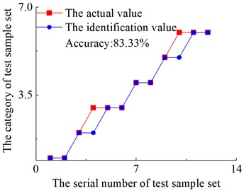
FNN is used to identify the fault types of six fault types of high-speed spur gears, including normal state. Each fault type has 10 groups of data. Eight groups of data in each fault type are randomly selected as training samples, and the remaining two groups are used as prediction samples. The prediction results extracted by EMD and VMD feature parameters are shown in Fig. 3.
It can be concluded that the accuracy of fault type recognition by neural network after EMD and VMD feature extraction is 83.3 % and 100 % respectively from Fig. 3. And the misclassification of the features extracted by the FNN for EMD is concentrated between 2 and 6, that is, between the eccentricity fault and the tooth surface wear fault of gear. The other faults can be accurately identified. And the recognition accurate rate of the fault feature vectors which were obtained by VMD have reached 100 %.
5. Conclusions
In this paper, the high-speed spur gear in the transmission system of wind turbine is taken as the object of study. The EMD and VMD decomposition method are used to decompose the original signals of spur gear in different fault states, and then construct the eigenvectors of different faults type. FNN is adopted to learn fault types and eigenvector samples to identify fault types. It can be seen that the fault type recognition accuracy of the features extracted by EMD and VMD decomposition is 83.33 % and 100 %, respectively. The VMD method is significantly better than the EMD method in terms of gear fault type identification.
Fig. 3Fault type identification errors: The vertical coordinates 1-5 are represented as: 1 – normal state; 2 –eccentricity fault; 3 – broken tooth fault; 4 – tooth missing fault; 5 – root wear fault; 6 – tooth surface wear fault
a) The fault feature vectors obtained by EMD
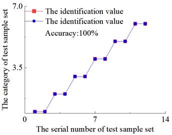
b) The fault feature vectors obtained by VMD
References
-
L. Xiang and H. W. Zhu, “Research on fault warning method of wind turbine gearbox based on CAE and BiLSTM,” (in Chinese), Journal of Chinese Society of Power Engineering, Vol. 42, No. 6, pp. 513–521, 2022.
-
X. Chen, “Research and application of condition monitoring and fault diagnosis technology in wind turbines,” (in Chinese), Journal of Mechanical Engineering, Vol. 47, No. 9, p. 45, Jan. 2011, https://doi.org/10.3901/jme.2011.09.045
-
Y. J. Wu, C. G. Zhen, and C. L. Liu, “Application of variational mode decomposition in wind power fault diagnosis,” (in Chinese), Journal of Mechanical Transmission, Vol. 39, pp. 129–132, 2015.
-
X. An and H. Zeng, “Fault diagnosis method for spherical roller bearing of wind turbine based on variational mode decomposition and singular value decomposition,” Journal of Vibroengineering, Vol. 18, No. 6, pp. 3548–3556, Sep. 2016, https://doi.org/10.21595/jve.2016.16553
-
W. Yang, Z. Peng, K. Wei, P. Shi, and W. Tian, “Superiorities of variational mode decomposition over empirical mode decomposition particularly in time-frequency feature extraction and wind turbine condition monitoring,” IET Renewable Power Generation, Vol. 11, No. 4, pp. 443–452, Jun. 2016, https://doi.org/10.1049/iet-rpg.2016.0088
-
L. Cao and W. Sun, “Research on bearing fault identification of wind turbines’ transmission system based on wavelet packet decomposition and probabilistic neural network,” Energies, Vol. 17, No. 11, p. 2581, May 2024, https://doi.org/10.3390/en17112581
-
T. Liu, Z. Luo, J. Huang, and S. Yan, “A comparative study of four kinds of adaptive decomposition algorithms and their applications,” Sensors, Vol. 18, No. 7, p. 2120, Jul. 2018, https://doi.org/10.3390/s18072120
-
G. J. Lal, E. A. Gopalakrishnan, and D. Govind, “Epoch estimation from emotional speech signals using variational mode decomposition,” Circuits, Systems, and Signal Processing, Vol. 37, No. 8, pp. 3245–3274, Mar. 2018, https://doi.org/10.1007/s00034-018-0804-x
-
H. Zang et al., “Hybrid method for short‐term photovoltaic power forecasting based on deep convolutional neural network,” IET Generation, Transmission and Distribution, Vol. 12, No. 20, pp. 4557–4567, Sep. 2018, https://doi.org/10.1049/iet-gtd.2018.5847
-
M. Bertier, M. Perrin, and C. Tedeschi, “On the complexity of concurrent multiset rewriting,” International Journal of Foundations of Computer Science, Vol. 27, No. 1, pp. 67–83, Mar. 2016, https://doi.org/10.1142/s0129054116500052
About this article

The paper is supported by funding project with the number of BS190220.
The datasets generated during and/or analyzed during the current study are available from the corresponding author on reasonable request.
The authors declare that they have no conflict of interest.
