Abstract
The existing Pascal curve gears suffer from limited flexibility in pitch curves and restricted changes in transmission ratios. This has impeded the application in a range of mechanical systems that require more adaptable gear solutions. For this, a design procedure for higher-order multisegment denatured Pascal curve gear is proposed. This innovative design offers greater flexibility in pitch curves and allows for a broader range of transmission ratios. The analysis of the transmission ratio confirms the theoretical predictions and highlights the effectiveness of the proposed gear design in achieving variable transmission ratios. The transmission mechanism of the higher-order multisegment denatured Pascal curve gear is analyzed and the unified mathematical expression of the families of Pascal curve gear is derived. The non-circular gears with free-form pitch curves can be obtained from higher-order multi-segment denatured Pascal curves by adjusting design parameters to unify different types of pitch curves. This approach provides significant flexibility in achieving specific transmission characteristics. Then the transmission characteristics are discussed. To further validate the design, the visual analysis and design software of the higher-order multisegment denatured Pascal curve gear is compiled based on Visual Basic, and is verified with the example. The novelty Pascal curve gears is applied to drive the differential velocity vane pump. The displacement, instantaneous flow rate, and pulsation rate of the differential velocity vane pump are calculated. The novelty drive mechanism could meet the requirements and have good performance. The application shows that the higher-order multisegment denatured Pascal curve gear is feasible in practice.
1. Introduction
Gears are recognized as the most effective components for transmitting mechanical power. They are characterized by very high efficiency, reliability, compact design – to name but a few properties. Many researchers devoted their work to investigate different aspects of gears, such as fatigue monitoring [1], optimization design [2], thermal loading [3], etc. For some mechanisms (especially automatic mechanisms) that require variable transmission ratios, circular gears are difficult to meet, while non-circular gears can achieve continuous variable transmission ratios. This paper considers non-circular gears.
Compared with the uniform transmission of standard circular gears, non-circular gears can be accurately designed for intended movements to achieve periodic nonuniform transmission. The most significant characteristic of non-circular gears is that the transmission ratio is variable, and their instantaneous transmission ratio changes in accordance with a specific law [4]. Due to their precise transmission and ease of balance, non-circular gears are widely applied in agricultural machinery [5], packaging machinery, and light industry machinery [6], such as rice transplanter, pumps and textile machines. A novel weft insertion mechanism named eccentric conjugate non-circular gears train weft insertion mechanism was proposed in order to better meet the requirements of rapier loom's weft insertion mechanism as well as reduce the manufacturing difficulty [7]. Wan et al. designed a new type of transplanting mechanism, which uses eccentric gears and non-circular gear planetary gear train as transmission components, and adopts a non-circular gear transplanting rotating box and a double needle pushing planting mechanism [8].
According to the law of gear meshing, the pitch curves of the gears with variable transmission ratios are no longer circular curves but non-circle curves. These non-circular gear pitch curves can be broadly classified into typical-form pitch curve and free-form pitch curve.
The free-form pitch curve cannot be clearly expressed with a mathematical function but often in segmental curves. A method for constructing the -lobe non-circular gear satisfying a specified displacement law with Bézier curve and B-spline curve was presented by Riaza [9]. Fanghella, P. presented a new method for designing non-circular gears under a given law of motion based on a mixed symbolic-numeric approach [10]. Liu Dawei et al. proposed a method to create pitch curves of noncircular gears based on compensation. When the given transmission ratio function cannot meet the closed conditions, one or more transmission ratio functions can be constructed to obtain a closed pitch curve according to the requirements of smooth curve [11]. Li Ge et al. proposed to express the pitch curves with nonfunction expression by means of numerical points instead of any function for fitting complex form pitch curves [12]. Yu Gaohong et al. divided the transmission ratio into three suitable segments and obtained a satisfactory transmission ratio function for each segment to construct the pitch curve equations, and applied the gears to the pick-up mechanism [13]. Considering generation of free pitch curve, Xu Gaohuan et al. used B-spline curve to establish a mathematical model of free pitch curves for non-circular gears under transmission and applied it to the differential pump [14].
Gears with typical-form pitch curve can be expressed with mathematical models, such as elliptical gear, Fourier non-circular gear and eccentric gear. Elliptical gear is the most commonly used gear and has been extensively and theoretically studied. Subsequently, denatured elliptical gear and high-order elliptical gear are proposed by adjusting the number of cycles of the pitch curves [15]-[17]. Additionally, non-circular gears with typical-form pitch curve have also been vigorously explored and investigated in the design and transmission characteristics, including eccentric non-circular gears [18], Fourier non-circular gears [19], and Pascal curve gears [20], to further enrich the gear transmission form.
In the studies of Pascal curve gears, Liao Wei et al. explored the pitch curve equations of general Pascal curve gear and applied to the separate transplanting mechanism [21]. Liu Yongping et al. probed into the meshing characteristics of Pascal curve gear and designed the tooth profile of Pascal curve gear according to the tooth profile conversion method, proving a theoretical basis for the processing of gears [22]. Yu Jun et al. deduced the functional relationship between the pitch curve and rotational angle of driven gear by adopting the numerical method, and obtained the pitch curve equation [23]. Moreover, the mathematical equation of pitch curve with cycles for high-order Pascal curve gear was presented, and the center distance was deduced using the residue theorem [24]. On this basis, Tao et al. proposed the high-order denatured Pascal curve gear and explored its transmission characteristics, further expanding the transmission means of the Pascal curve gear [25]. However, these studies are all confined by limited changes in the transmission ratio.
The varying forms of pitch curves make it impossible to obtain non-circular gears with free-form pitch curve, thereby increasing the great difficulty of standardized design. While non-circular gears with typical-form pitch curve have less flexible pitch curves and limited changes in transmission ratios, they are unable to satisfy a broader range of transmission requirements. To unify these two kinds of non-circular gears and standardize the design, a higher-order multisegment denatured Pascal curve gear is proposed to construct non-circular gears with free-form pitch curve. This novel Pascal curve gear divides the pitch curve into more than three segments in each cycle and makes the pitch curve more changeable, which enriches the transmission types of gears. Then the gears were applied to drive the differential velocity vane pump (DVVP). This drive mechanism can realize the periodic non-uniform speed rotation of the impeller of the pump and make its adjacent vanes open and close periodically to realize the change in closed volume to complete the liquid discharge and suction process.
In this article, section 2 proposes the transmission mechanism of the new type Pascal curve gear and a mathematical model is built. In section 3 the visual analysis and design software is developed and a design case is illustrated to verify the feasibility of the proposed gears. Then, an application is given. Finally, the conclusion of this study is given.
2. Design of high-order multisegment denatured pascal curve gears
2.1. Transmission mechanism of multisegment denatured pascal curve gears
The trajectory of points with the same distance l in the radial direction from any point of the base circle is called Pascal curve. The gear that takes the closed curve formed by the Pascal curve as the pitch curve is called Pascal curve gear. In a pair of gears, driving gear 1 is a Pascal curve gear and the driven gear 2 is a non-circular gear that conjugates with the driving gear 1, as indicated in Fig. 1. The equation of pitch curve is [22]:
where is the radius of Pascal curve gear, is stretched length, is the diameter of the occurrence circle, is the polar angle.
On the basis of this equation, keep the radius of each point on the pitch curve unchanged, and then turn the polar angle into , that is, the original polar angle becomes , and the -order Pascal curve gear can be obtained.
Fig. 1Pitch curve of Pascal curve gear
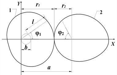
Based on the above analysis, the equation of pitch curve of the higher-order Pascal curve gear 1 are as follows:
where is order of Pascal curve gear.
The pitch curve expressed in Eq. (2) is still a typical form and cannot replace non-circular gear with free pitch curve. Thus, the flexibility to optimize transmission characteristics is limited.
Fig. 2The higher-order Pascal curve gears
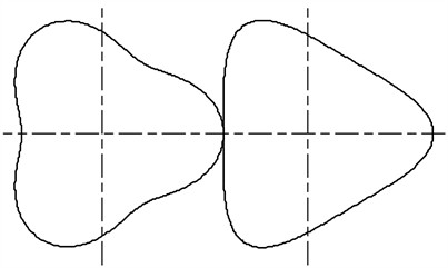
The transmission ratio of the general Pascal curve gear changes symmetrically based on . However, the transmission ratio can be adjusted into an asymmetrical form through denaturation. To obtain a broader range of transmission ratios, the transmission ratio is adjusted to an asymmetrical form at , namely, the pitch curve is separated into () segments through denaturation and every segment is a denatured Pascal curve. Therefore, the pitch curve of the multisegment denatured Pascal curve gear is continuous and forms a closed curve that connects end to end [26]:
where is radius of Pascal curve for segment , is the sequence number of segment and , is quantity of segments, is denatured coefficient, and should satisfy with the Eq. (4):
According to Eq. (3), when:
When and :
Thus, the pitch curve of a multisegment denatured non-circular gear formed by Eq. (3) is continuous at, and . Therefore, the pitch curve of the multisegment denatured Pascal curve gear is continuous and forms a closed curve that connects end to end.
2.2. Transmission mechanism of high-order multisegment denatured pascal curve gears
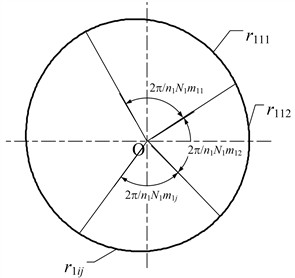
As shown in Fig. 4, combined with the generation principles of pitch curves for a higher-order Pascal curve gear and a multisegment denatured Pascal curve gear, the pitch curve in each cycle is separated into segments to form the higher-order multisegment denatured Pascal curve gear. The represents the radius of the driving gear 1 for the first segment of the first cycle. The represents the radius of the driving gear 1 for the second segment of the first cycle. The represents the radius of the driving gear 1 for the segment of the cycle.
The expression of pitch curve of driving gear can be written as the following:
where is cycle number of the driving gear and , is radius of the driving gear 1 for segment of cycle .
Fig. 3The multi-segment denatured Pascal curve gears
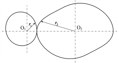
Fig. 4Schematic diagram of pitch curve
To ensure the continuity of the section curve, calculation verification is carried out at each segment point and adjacent segment point within each cycle.
According to Eq. (7), in any cycle , when :
Eq. (8) shows that every segment of the denatured pitch curve within each cycle connects from end to end.
According to Eq. (7), at the junction of any adjacent cycles, when or :
Eq. (9) shows that every segment of the denatured pitch curve connects from end to end in adjacent cycles.
Therefore, the pitch curve given by Eq. (7) is a continuous closed curve. Within a cycle of , each segment is connected end to end.
In compliance with the fundamental meshing rule, the alteration in angular displacements of two gears should be accomplished in the same period, and the relationship can be obtained as [7]:
The closure requirement for the pitch curves has been established as:
where is order of driven gear.
The center distance can be determined using Eq. (11). The center distance is obviously controlled by the design parameters: , , , , , and . The process of solving the center distance is shown as follows:
(1) Searching the unimodal interval where the center distance is located with the Advance-Retreat Method.
(2) Determining the center distance with the Golden Section Method.
From Eqs. (7) and (11), the radius and polar angle of the driven gear can be calculated as Eqs. (12) and (13), respectively:
Clearly, the driven gear that conjugates with the driving gear is a -order and -segment non-circular gear, which means that when the driving gear runs circles, the driven gear runs circles. For different quantities of segment :
(1) when 1, 1, and 1, the driving gear 1 is a general Pascal curve gear and the driven gear 2 is a non-circular gear that conjugates with the driving gear 1.
(2) when 2, the driving gear 1 is a higher-order denatured Pascal curve gear and the driven gear 2 is a higher-order denatured gear that conjugates with the driving gear 1.
(3) when , both the driving gear 1 and the driven gear 2 are essentially non-circular gears with different orders and -segment.
For different quantities of segment , the general Pascal curve gear, higher-order denatured Pascal curve gear, and higher-order multisegment denatured Pascal curve gear can be obtained.
The higher-order multisegment denatured Pascal curve gear can obtain different numbers of blades with different orders, which can realize multiple periodic transmission ratios. This novel gear can change the transmission ratio into segments, which can meet more nonuniform transmission characteristics requirements.
Therefore, the higher-order multisegment denatured Pascal curve gear proposed in this paper is more general and unified in theory, and more extensive in practice, which covers the higher-order Pascal curve gear and multisegment denatured Pascal curve gear.
The proposed method involves dividing the pitch curve into multiple segments within each cycle. Each segment can be individually adjusted by modifying the design parameters, allowing for a wide range of pitch curve shapes.
By changing the design parameters such as , , , , and , the non-circular gears with free-form pitch curve can be composed of the higher-order multisegment denatured Pascal curve gears. The pitch curve can be tailored to achieve specific transmission characteristics. This flexibility facilitates the creation of non-circular gears with free-form pitch curves that meet diverse application requirements.
The higher-order multi-segment denatured Pascal curve approach provides a theoretical basis for unifying different types of pitch curves, integrating the benefits of typical-form and free-form pitch curves into a single design framework.
3. Analysis of transmission ratio
Based on the principle of gear transmission, the transmission ratio of a pair of higher-order multisegment denatured Pascal curve gears is expressed as Eq. (14):
When , gets the minimum:
When , gets the maximum:
Therefore, according to Eqs. (15) and (16), the maximum and minimum transmission ratios are designed to determine the scope of .
The comparative analysis of their transmission performance is conducted based on the equal center distance of elliptical gears, eccentric non-circular gears, and Pascal curve gears.
From Table 1, it can be seen that when the center distance is greater than 100 mm, the transmission ratio of Pascal curve gears has a larger variation range under certain parameters. As the center distance increases, the variation range of transmission ratio gradually decreases for eccentric non-circular gears, and the variation range of transmission ratio of the elliptical gear is independent of the center distance.
Table 1Comparison of transmission ratios
The center distance | Pascal curve gear | Eccentric non-circular gear | Elliptical gear | |||
Maximum | Minimum | Maximum | Minimum | Maximum | Minimum | |
90 | 3.487 | 1.525 | 4.938 | 1.007 | 3.000 | 0.333 |
96 | 4.133 | 1.471 | 4.636 | 1.044 | 3.000 | 0.333 |
103 | 4.720 | 1.416 | 4.311 | 1.090 | 3.000 | 0.333 |
110 | 5.153 | 1.369 | 4.087 | 1.127 | 3.000 | 0.333 |
116 | 5.532 | 1.301 | 3.902 | 1.161 | 3.000 | 0.333 |
3.1. Concavity and convexity
The pitch curves of the higher-order multisegment denatured Pascal curve gear may be concave. To drive stably and process conveniently, the concavity and convexity of the pitch curves shall be verified.
The curvature radius of pitch curve of the higher-order multisegment denatured Pascal curve gear is obtained based on the knowledge of differential geometry [26]:
For the driving gear, the derivations of the first segment in each cycle of the pitch curve are calculated from Eq. (7):
The curvature radius can be solved by substituting Eqs. (18) and (19) into Eq. (17).
The pitch curve is convex when the curvature radius meets the following Eq. (20):
From Eq. (17), it can be seen that the numerator is greater than zero, if the denominator , the pitch curve of this segment becomes convex.
When , the curvature radius of the first segment reaches its minimum, so the convexity distinguished condition of this segment can be simplified as Eq. (21):
If , then the convexity distinguished condition is expressed below:
Namely:
For the driving gear, the convexity distinguished condition in each segment is obtained below:
Similarly, the convexity distinguished conditions of the driven gear is derived.
The concave curve may cause the gear to get stuck when the meshing transmission reaches this point, which is not allowed in actual gear meshing transmission. In addition, if the pitch curve is concave, non-circular gears cannot be machined using the hobbing method, and only be cut using slotting machine.
3.2. Compiling of design software and design case
To better analyze their transmission characteristics, the visual design and simulation software and generation software of the tooth profile for non-circular gears are compiled by using Visual Basic according to the equations of pitch curve of the higher-order multisegment denatured Pascal curve gear, which have been established in section 2, as shown in Fig. 5. Fig. 5 demonstrates the interface and key functions of the software, which is developed to simulate and visualize the gear design process. This allows for the generation of precise pitch curves and other geometric characteristics of the multisegment denatured Pascal curve gears.
The design of functional non-circular gears is a complex task that involves ensuring smooth meshing and accurate transmission ratios. Advanced simulation tools, such as the Visual Basic-based software developed in this study, are essential for refining the gear design and validating its performance.
Based on mechanism parameters (, , , , and ), the software can obtain the center distance, the transmission ratio and curvature radius, as well as the kinematic curves of the driven gear, including displacement, velocity and acceleration. The software can also simulate the movement of the pitch curves.
Fig. 5Software of visual design and simulation
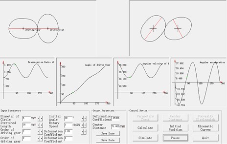
In order to facilitate the design and generation of non-circular gear tooth profiles, a software for generating external meshing non-circular spur gear tooth profiles is developed. After importing the data of the pitch curve and selecting the modulus and pressure angle, the software calculates the number of teeth based on the pitch curve circumference and modulus. This software is based on the mathematical model of the rotational cutting motion of the hobbing tool around the workpiece. Using the software's fast calculation function, it draws the non-circular gear shape enclosed by the tool’s tooth profile, calculates the tooth profile points of the non-circular gear, and saves the data of tooth profile shape. And the data of tooth profile is imported into a 3D design software (such as Solidworks) for 3D graphic drawing.
A pair of gears meets the conditions as follows: 5 mm, 23 mm, 3, 5, 3, 0.95 and 1.2. The visual design and simulation software is utilized for obtaining a group of parameters: 62.18 mm and 0.897. The pitch curves and 3D modeling of gears in the example are showed in Fig. 6. Fig. 6 is a schematic diagram of the pitch curves of the third-order three-multisegment and fifth-order three-multisegment non-circular gear pair.
Fig. 6Example
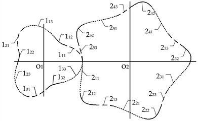
a) Pitch curves of gears
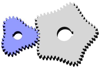
b) 3D modeling of gears
4. Application and discussion
4.1. DVVP driven by higher-order multisegment denatured Pascal curve gears
The differential velocity vane pump drives the adjacent vanes to rotate at differential rotation via the driving mechanism to achieve periodic changes in the volume and realize suction and drainage. The primary technology of the pump lies in its driving mechanism, which makes the vane speed change regularly. The non-circular gear mechanism has a small inertia force and compact structure, which is very suitable for applications with large displacement and high efficiency, and has become the most widely used driving mechanism for DVVP.
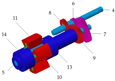
Fig. 7Diagram of the pump: 1 – motor; 2 – clutch; 3 – gearbox; 4 – input shaft; 5 – out shaft; 6 – first driving gear; 7 – first driven gear; 8 – second driving gear; 9 – second driven gear; 10 – first impeller; 11 – second impeller; 12 – pump shell; 13 – front shaft sleeve; 14 – rear shaft sleeve
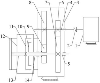
a) Schematic of mechanism
b) 3D model
Fig. 7 is the diagrams of the differential pump. The two identical pairs of higher-order multisegment denatured Pascal curve gears are installed on the same axis with the installation angle . The impellers can achieve differential motion during the rotation of the non-circular gears with non-uniform speed periodically. Thus, the volumes of the enclosed cavities change to realize suction and drainage periodically.
The displacement of the pump is as follows based on the differential velocity vane pump theory [14]:
where is the maximum tension angle of two adjacent vanes, is the minimum tension angle of two adjacent vanes, is the thickness of the vane, is the radius of the impeller, and the is radius of the impeller shaft.
The instantaneous flow rate of the pump is [14]:
where is the volume of drainage cavity, is the angular velocity of the input shaft, .
To reduce the pulsation rate, it is usually necessary to use two differential pumps in parallel, and the phase difference between two four-vane differential pumps in parallel is . The instantaneous flow rate of the double pumps in parallel is:
The pulsation rate is:
where is the average instantaneous flow rate, is the maximum instantaneous flow rate, is the minimum instantaneous flow rate.
4.2. The influences of parameters on the performance of the DVVP
There are many parameters that affect the performance of the DVVP, and the paper mainly focuses on the parameters related to the non-circular gear. Thus, only the effects of the quantity of segments and denatured coefficients are analyzed here.
The changes in the quantity of segments and denaturation coefficients can affect the local transmission ratio of non-circular gear. Based on the mathematical models, the transmission ratio affects important performance indicators of the pump, such as the instantaneous flow, pulsation rate and displacement. In order to analyze the influences of these parameters, the other parameters of the pitch curves remain unchanged, the quantity of segments and denaturation coefficients are adjusted and the impact on the pulsation rate and displacement of the pump are analyzed.
Take the four-vane DVVP as an example in the paper, select a group of parameters of non-circular gears: , 2, 4 mm, 28 mm, 2, the effects of denaturation coefficients on pulsation rate and displacement are shown in Table 2.
The effects of the quantity of segments on pulsation rate and displacement are shown in Table 3 under a group of parameters of non-circular gears: , , 4 mm, 28 mm.
As the quantity of segments and denaturation coefficients increase, the pulsation rate of the single pump decreases, while the pulsation rate of the double pumps in parallel increases. The main reason is that the quantity of segments and denaturation coefficients increase, the local deformation of the pitch curve causes changes in the transmission ratio, the fluctuation of flow curve decreases and the pulsation rate of the single pump decreases. For the double pumps in parallel, the local deformation of the pitch curve intensifies and the asymmetry becomes more pronounced, which changes the optimal phase of the superposition of the double pumps, resulting in an increase in the pulsation rate of the two pumps.
Table 2Effect of denaturation coefficients on pulsation rate and displacement
Denaturation coefficients | Concavity | Pulsation rate of single pump / % | Pulsation rate of double pumps / % | Displacement / mL |
1.0 | Convexity | 156.8 | 31.4 | 3875 |
1.1 | Convexity | 155.0 | 32.3 | 3892 |
1.2 | Micro-convaxity | 150.3 | 33.7 | 3916 |
1.3 | Concavity | 148.2 | 36.9 | 3947 |
1.4 | Concavity | 146.9 | 40.1 | 3989 |
Table 3Effect of the quantity of segments on pulsation rate and displacement
Quantity of segments | Concavity | Pulsation rate of single pump / % | Pulsation rate of double pumps / % | Displacement / mL |
1 | Convexity | 156.8 | 31.4 | 3875 |
2 | Convexity | 155.0 | 32.3 | 3892 |
3 | Convexity | 153.6 | 34.8 | 3920 |
4 | Concavity | 152.7 | 39.4 | 3934 |
The displacement of the pump increases with the increase of the quantity of segments and denaturation coefficients. The main reason for the increase in displacement is that the change in pitch curve causes an increase in the effective volume of the pump.
The effects of the are can also be obtained, as shown in Table 4.
Table 4Effects of the ε=b/l on pulsation rate and displacement
Concavity | Pulsation rate of single pump / % | Pulsation rate of double pumps / % | Displacement / mL | |
0.13 | Convexity | 156.6 | 31.6 | 3949 |
0.15 | Convexity | 156.9 | 31.4 | 3890 |
0.17 | Convexity | 157.3 | 30.9 | 3717 |
0.21 | Concavity | 158.2 | 30.1 | 3491 |
The ideal working state of the differential pump is to obtain a large displacement and low pulsation rate under the condition of ensuring normal transmission. The analysis showed that these parameters were beneficial to improving the performance of the differential pump.
Based on the above analysis, the performance of the DVVP is compared under different parameters and select a group of parameters of non-circular gears with good performance: , , mm, 62 mm, 3, 1.08, 0.93 and 1. The tooth profiles are shown in Fig. 8.
When the parameters of the pump are 90 mm, 20 mm, and 50 mm, the theoretical maximum displacement of the pump is 3852 mL. The instantaneous flow rate of the single pump fluctuates between 0 and 24025 mL/s, and there are nondrainage sections periodically ( 0). To realize drainage continuously, double pumps should be used in parallel. The instantaneous flow rate of the double pump in parallel is stable between 24281 and 33902 mL/s. The curves of instantaneous flow rate of the single pump and double pumps in parallel are shown in Fig. 9.
The pulsation rate of a single pump is 155.1 %. The pulsation rate of the single pump is relatively high and cannot meet the production requirements. After the use of double pumps in parallel, the pulsation rate drops significantly, with the pulsation rate of only 32.1 %.
The ability to adjust the pitch curves by altering the design parameters serves to fine-tune the pitch curves on the localized level. Thus the optimal parameters of the non-circular gears for driving differential pump can be obtained. This ensures that the pump achieves a large displacement and low pulsation rate, thereby enhancing its overall performance.
Fig. 8Tooth profiles of gears
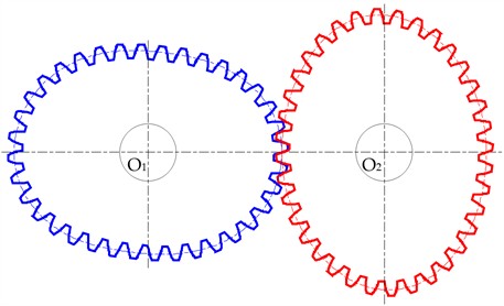
Fig. 9The curves of instantaneous flow rate

a) Single pump

b) Double pumps in parallel
5. Experiment and performance comparison
To verify the accuracy of the theoretical model of the DVVP driven by higher-order multisegment denatured Pascal curve gears, an experimental platform is established. The power of the experimental platform is a 5 kW motor, which is controlled by a frequency converter for speed regulation. A speed measurement sensor is installed between the motor and the differential pump. This platform is designed to evaluate the performance of the four-vane differential pump. The experimental platform is shown in Fig. 10.
The comprehensive characteristic experiment of the differential pump mainly includes the transmission ratio test and the displacement test.
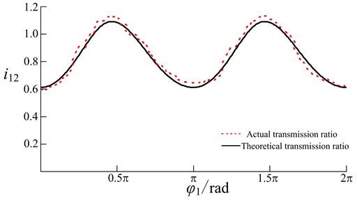
The transmission ratio test uses a high-precision laser velocimeter to measure the real-time rotation speed of the driving gear and the driven gear, then calculates to obtain the actual transmission ratio of the gears, and compares it with the theoretical transmission ratio. Comparing the ratio curves in Fig. 11.
As shown in Fig. 11, the transmission ratio of the higher-order multisegment denatured Pascal curve gears is continuous and divided into three asymmetrical segments within each cycle. The figure demonstrates how the transmission ratio varies across the different segments, providing a visual confirmation of the theoretical models discussed in the paper. It can be seen that the trend and value range of the transmission ratio curve obtained from the experiment are basically consistent with the theoretical transmission ratio.
Fig. 10Experimental platform: 1 – pump; 2 –gear box
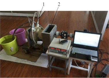
Fig. 11Comparing the ratio curves
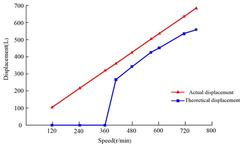
The displacement test of the differential pump mainly focuses on the volume of liquid discharged per minute at different rotation speeds, and compares it with the theoretical displacement to study the efficiency of the differential pump, as shown in Table 5.
Table 5Results of the displacement test
Sequence | Input speed / /min | Theoretical displacement / | Actual displacement / | Volumetric efficiency / % |
1 | 118 | 105.02 | 0 | 0 |
2 | 243 | 216.27 | 0 | 0 |
3 | 357 | 317.73 | 0 | 0 |
4 | 406 | 361.34 | 266.67 | 73.8 |
5 | 478 | 424.42 | 340.81 | 80.3 |
6 | 565 | 502.85 | 425.91 | 84.7 |
7 | 602 | 535.78 | 451.66 | 84.3 |
8 | 714 | 635.46 | 535.59 | 84.6 |
9 | 769 | 684.41 | 557.79 | 81.5 |
In the initial stage, the input speed is low and the differential pump does not discharge any liquid. It is mainly due to the seal performance of the pump failing to reaching the optimal state, which affects the self suction performance of the pump. When the speed exceeds 406 r/min, the differential pump begins to discharge liquid, and the volumetric efficiency is around 84 %. When the speed increases to 739 r/min, the volumetric efficiency significantly decreases. The main reason is that as the speed increases, the internal pressure increases and the internal leakage also increases, resulting in a decrease in the efficiency of liquid discharge.
According to the Fig. 12, it can be found that the theoretical displacement and actual displacement curves of the differential pump are basically similar under the discharge condition. These curves exhibit a linear relationship and follow a similar trend, thereby validating the accuracy of the calculation model of the differential pump.
Fig. 12The relationship between speed and displacement
6. Conclusions
1) This paper presents a novel design approach for higher-order multisegment denatured Pascal curve gears, developed through a analysis of both higher-order Pascal curve gears and multisegment denatured Pascal curve gears. The unified mathematical models for these families of Pascal curve gears expand their potential applications. This methodology not only broadens the scope for Pascal gears but also enhances the versatility of non-circular gears with typical-form pitch curves, such as eccentric gears and Fourier curve gears, making them more practical for diverse engineering applications.
2) The design parameters of the higher-order multisegment denatured Pascal curve gear can be adjusted to conveniently modify the shape of its pitch curves. This flexibility allows for the creation of non-circular gears with free-form pitch curves, offering a unified theoretical framework for designing both types of gears. The proposed mathematical expressions were implemented into a visual design and simulation tool, which was verified through an example, demonstrating the practical utility of the approach.
3) The higher-order multisegment denatured Pascal curve gear proves effective in the drive mechanism of differential pumps. Analysis confirms that these non-circular gears meet the functional requirements of the pump system, showcasing the feasibility of the designed mechanism. The results confirmed that the proposed higher-order multisegment denatured Pascal curve gears can achieve the desired transmission ratios and improve the performance of mechanical systems such as differential pumps. An experimental platform was constructed to test the liquid output volume of the differential pump, assessing displacement and volumetric efficiency at various rotational speeds. The results verify that the proposed gears mesh correctly and can be applied in practical scenarios.
4) Despite the promising results, several limitations should be addressed in future work:
– Manufacturing complexity: The production of higher-order multisegment denatured Pascal curve gears can be complex, particularly when fine adjustments to the pitch curves are required. Future research should explore more efficient manufacturing techniques or alternative materials to simplify production and reduce costs.
– Operational conditions: The current study assumes idealized conditions for the differential pump and its application of Pascal curve gears. Future studies could explore how these gears perform under more variable and real-world operational conditions, incuding varying temperatures, pressures, and wear factors.
– Broader applications: Future research could investigate the application of higher-order multisegment denatured Pascal curve gears in other mechanical systems, such as automotive transmissions, robotics, and aerospace engineering. These fields could benefit from the flexibility and efficiency offered by this gear design.
References
-
K. Vučković, I. Čular, R. Mašović, I. Galić, and D. Žeželj, “Numerical model for bending fatigue life estimation of carburized spur gears with consideration of the adjacent tooth effect,” International Journal of Fatigue, Vol. 153, p. 106515, Dec. 2021, https://doi.org/10.1016/j.ijfatigue.2021.106515
-
D. Miler, D. Žeželj, A. Lončar, and K. Vučković, “Multi-objective spur gear pair optimization focused on volume and efficiency,” Mechanism and Machine Theory, Vol. 125, pp. 185–195, Jul. 2018, https://doi.org/10.1016/j.mechmachtheory.2018.03.012
-
A. Miltenović, M. Tica, M. Banić, and Miltenović, “Prediction of temperature distribution in the worm gear meshing,” Facta Universitatis, Series: Mechanical Engineering, Vol. 18, No. 2, p. 329, Jul. 2020, https://doi.org/10.22190/fume180120016m
-
D. Mundo, “Geometric design of a planetary gear train with non-circular gears,” Mechanism and Machine Theory, Vol. 41, No. 4, pp. 456–472, Apr. 2006, https://doi.org/10.1016/j.mechmachtheory.2005.06.003
-
S. Maláková, M. Urbanský, G. Fedorko, V. Molnár, and S. Sivak, “Design of geometrical parameters and kinematical characteristics of a non-circular gear transmission for given parameters,” Applied Sciences, Vol. 11, No. 3, p. 1000, Jan. 2021, https://doi.org/10.3390/app11031000
-
A. Prikhodko, “Experimental kinematic analysis of an intermittent motion planetary mechanism with elliptical gears,” Journal of Measurements in Engineering, Vol. 8, No. 3, pp. 122–131, Sep. 2020, https://doi.org/10.21595/jme.2020.21583
-
J. N. Chen, H. C. Zhao, Y. Wang, G. H. Xu, and M. Zhou, “Kinematic modeling and characteristic analysis of eccentric conjugate non-circular gear and crank-rocker and gears train weft insertion mechanism,” Journal of Donghua University, Vol. 30, No. 1, pp. 15–20, 2013, https://doi.org/10.19884/j.1672-5220.2013.01.003
-
S. W. Wan and J. H. Pang, “The designing and making of the pitch curve about non-circular gears with double needle pushing-planting mechanism,” (in Chinese), Machinery Design and Manufacture, Vol. 11, pp. 181–183, 2019, https://doi.org/10.19356/j.cnki.1001-3997.2019.11.046
-
H. F. Quintero Riaza, S. C. Foix, and L. J. Nebot, “The synthesis of an n-lobe noncircular gear using Bézier and B-Spline nonparametric curves in the design of its displacement law,” Journal of Mechanical Design, Vol. 129, No. 9, pp. 981–985, Sep. 2007, https://doi.org/10.1115/1.2748453
-
P. Fanghella, “Kinematic synthesis and design of non-circular gears through a symbolic-numeric modeling approach,” in ASME International Design Engineering Technical Conferences and Computers and Information in Engineering Conference, pp. 781–789, Jan. 2005, https://doi.org/10.1115/detc2005-84458
-
D. Liu, “Creating pitch curve of closed noncircular gear by compensation method,” (in Chinese), Journal of Mechanical Engineering, Vol. 47, No. 13, p. 147, Jan. 2011, https://doi.org/10.3901/jme.2011.13.147
-
G. Li, K. Y. Ying, F. J. Zheng, J. B. Gu, and Z. W. Xu, “Design and experiment of noncircular gears transplanting mechanism based on pitch curve with nonfunction expression,” (in Chinese), Transactions of the CSAE, Vol. 30, No. 23, pp. 10–16, 2014, https://doi.org/10.3969/j.issn.1002-6819.2014.23.002
-
G. Yu, “Design of a rotary plug seedling pick-up mechanism,” (in Chinese), Journal of Mechanical Engineering, Vol. 51, No. 7, p. 67, Jan. 2015, https://doi.org/10.3901/jme.2015.07.067
-
G. H. Xu, R. S. Xie, P. F. Sun, and H. C. Zhao, “Design and experiment of differential pump driven by non-circular gear with free pitch curve,” (in Chinese), Transactions of the Chinese Society for Agricultural Machinery, Vol. 51, No. 4, pp. 411–417, 2020, https://doi.org/10.6041/j.issn.1000-1298.2020.04.048
-
M. Yazar, “Design, manufacturing and operational analysis of elliptical gears,” International Journal of Precision Engineering and Manufacturing, Vol. 22, No. 8, pp. 1441–1451, Jun. 2021, https://doi.org/10.1007/s12541-021-00549-3
-
K. H. Zhou, X. F. Li, and B. H. Xu, “Analysis of high-order elliptic gear transmission and its application in flowmeter,” (in Chinese), Machine Tool and Hydraulics, Vol. 49, No. 19, pp. 25–31, 2021, https://doi.org/10.3969/j.issn.1001-3881.2021.19.006
-
J. Han, Y. Liu, D. Li, and L. Xia, “External high-order multistage modified elliptical helical gears and design procedure of their gear pairs,” Proceedings of the Institution of Mechanical Engineers, Part C: Journal of Mechanical Engineering Science, Vol. 230, No. 16, pp. 2929–2939, Aug. 2016, https://doi.org/10.1177/0954406215603738
-
J. Ye, J. N. Chen, X. Zhao, X. C. Sun, X. D. Xia, and Q. F. Gao, “Design and applications of generalized eccentric noncircular gears,” (in Chinese), China Mechanical Engineering, Vol. 29, 2018, https://doi.org/10.3969/j.issn.1004-132x.2018.05.010
-
G. Xu, J. Chen, and H. Zhao, “Numerical calculation and experiment of coupled dynamics of the differential velocity vane pump driven by the hybrid higher-order Fourier non-circular gears,” Journal of Thermal Science, Vol. 27, No. 3, pp. 285–293, May 2018, https://doi.org/10.1007/s11630-018-1010-7
-
D. Liu and T. Ren, “Study on Deformed limacon gear and motion optimization of its serial mechanism,” Journal of Mechanical Design, Vol. 133, No. 6, pp. 1–8, Jun. 2011, https://doi.org/10.1115/1.4004116
-
W. Liao, Y. Zhao, and M. H. Fang, “Application of Pascal curve gear in transplanting mechanism and mechanical parameter optimization,” (in Chinese), Journal of Zhejiang Sci-Tech University, Vol. 26, No. 4, pp. 547–551, 2009, https://doi.org/10.3969/j.issn.1673-3851.2009.04.015
-
Y. P. Liu, P. Wang, X. L. Xian, and S. Y. Zhang, “Design of the tooth profile of Pascal curve gear,” (in Chinese), Journal of Mechanical Transmission, Vol. 39, No. 3, pp. 50–52, 2015, https://doi.org/10.16578/j.issn.1004.2539.2015.03.014
-
J. Yu, Y. P. Liu, H. C. Zhang, and Q. F. Zhang, “The design of limacon gear pair based on numerical method,” (in Chinese), Machinery Design and Manufacture, Vol. 5, pp. 217–219, 2016, https://doi.org/10.19356/j.cnki.1001-3997.2016.05.056
-
T. Z. Ren, D. W. Liu, and H. Y. Ben, “Design and transmission of limacon gear pair,” (in Chinese), Journal of Machine Design, Vol. 30, No. 1, pp. 55–59, 2013, https://doi.org/10.13841/j.cnki.jxsj.2013.01.022
-
D. H. Tao, N. Li, Z. Y. Xuan, X. Wang, and L. J. Zheng, “Analysis of generation mechanism of high-order deformed pascal snail line non-circular gear,” (in Chinese), Journal of Xihua University, Vol. 43, No. 3, pp. 45–53, 2024, https://doi.org/10.12198/j.issn.1673-159x.4774
-
C. Pany and S. Parthan, “Free vibration analysis of multi-span curved beam and circular ring using periodic structure concept,” Journal of the Institution of Engineers (India), IE (I)-AS, Vol. 83, pp. 18–24, 2002.
-
X. Ding, B. Hong, X. Sun, and W. Liu, “Approach to accuracy improvement and uncertainty determination of radius of curvature measurement on standard spheres,” Measurement, Vol. 46, No. 9, pp. 3220–3227, Nov. 2013, https://doi.org/10.1016/j.measurement.2013.05.022
About this article
This work was supported by the Natural Science Foundation of Zhejiang Province (Grant No. LY21E050002).
The datasets generated during and/or analyzed during the current study are available from the corresponding author on reasonable request.
Huacheng Zhao was responsible for formal analysis, methodology, software, and writing-original draft preparation. Jianneng Chen was responsible for conceptualization and writing-review, Gaohuan Xu was responsible for conceptualization, funding acquisition, visualization, and writing-review and editing.
The authors declare that they have no conflict of interest.
