Abstract
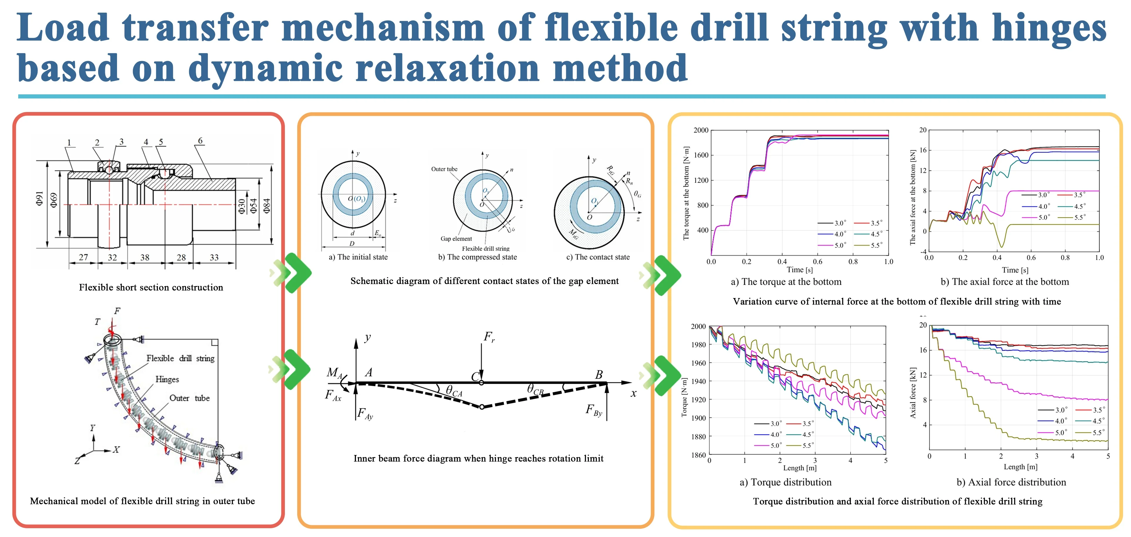
The flexible drill string with hinges is a unique structure for drilling ultra-short radius horizontal wells. In this paper, spatial beam elements are used to simulate the flexible drill string and outer tube, universal joint connection elements are used to simulate hinge joints, and contact gap elements are used to simulate the random contact between the flexible drill string and the outer tube. A nonlinear mechanical analysis model is established for the contact of the flexible drill string with hinges in the outer tube, and the dynamic relaxation method is adopted to solve the model. The correctness of the model and method is verified by an example with analytical solutions. Numerical calculations are conducted on six types of hinge rotation limits and six different single section lengths of flexible drill strings in the inclined section. The results illustrate that the contact force between the flexible drill string and the outer tube is discontinuous and randomly distributed along the axis. The hinge rotation limit is increased from 3° to 5.5°, the axial force transmitted to the bottom of the flexible drill string is reduced from 16.7 kN to 1.5 kN, and the torque transmitted to the bottom has little changed, and its values are close to 1900N·m. When the hinge rotation limit is greater than 5 degrees, the axial force loss rate is greater than 59.5 %. When the hinge rotation limit is 4 degrees, the axial force and torque transmitted to the bottom of the well have little change for flexible drill strings of different single section lengths.
Highlights
- Establish a nonlinear finite element model using the finite element method and gap element method.
- Introduce dynamic relaxation method to solve the model.
- The contact force between the flexible drill string and the outer tube is randomly distributed along the axial direction.
1. Introduction
The ultra-short radius horizontal well technology is an effective technology for developing the remaining oil. It has the advantages of being locatable, directional, and the location and degree of transformation can be controlled, comparing with fracturing and other transformation technologies [1]. It is not only suitable for heavy oil reservoirs, remaining oil reservoirs at the top of thick oil layers, locally trapped remaining oil, but also suitable for the oil which sand reservoirs with small scale, poor development efficiency, and difficult comprehensive adjustment. This technology can achieve effective development of these oil layers and tapping the potential of remaining oil [2-5]. Ultra-short radius horizontal well technology was applied for the first time by China National Offshore Oil Corporation (CNOOC) Zhanjiang Branch in Weizhou Oilfield, which achieving a drilling output of 3.5 times the allocated production in 2020 [6]. A certain oilfield of CNOOC applied ultra-short radius technology to drill four branch wells at a reservoir depth of about 3200 m and established a mechanical drilling speed prediction model for the horizontal section of ultra-short radius horizontal wells, which can provide a basis for predicting the construction period of ultra-short radius horizontal wells in 2022 [7]. Two successful application cases have demonstrated that this technology also has good application prospects in deep drilling and production of offshore oil fields.
Hydraulic jet tools and flexible drilling tools are two main types of drilling tools for ultra-short radius horizontal wells. For the mechanical analysis of downhole tools in ultra-short radius horizontal wells, Su Yinao [8, 9] regarded hinges as planar hinges, established a two-dimensional model of hinged drilling tools, and analyzed the stress situation at hinges. Liu [10, 11] conducted a study on the ultimate load of flexible drill strings in radial horizontal wells using theoretical analysis and finite element method. Wang Huiyi [12-14] used the finite element method to study the deformation of the cross-section of the ultra-short radius horizontal well drill string and established a differential equation between the resistance of the drill string inlet section and the trajectory of the inlet section. They studied the resistance characteristics of different shape inlet trajectories. Zhu [15] conducted structural optimization design and dynamic analysis on the hinge joint of flexible drill strings. Some scholars [16-19] have conducted research on the steering gear and steering mechanism in hydraulic jet drilling of ultra-short radius horizontal wells. Wang Zhifeng [20] conducted an analysis of the multiphase flow pattern of the drill bit nozzle in ultra-short radius horizontal wells to address the contradiction between drilling diameter and drilling depth in hydraulic jet drilling technology. Li [21] provided a calculation model for the self-propelled force of a rotating porous jet drill bit in ultra-short radius horizontal wells. Ma Dongjun [22] proposed a pressure loss calculation formula for the high-pressure hose section and established a relatively complete pressure loss calculation model for the circulation system of ultra-short radius horizontal wells. On this basis, Wang [23] considered the material differences of high-pressure hoses, introduced a friction correction coefficient, and conducted experimental research on the friction resistance of high-pressure hoses passing through the steering gear, obtaining the relationship between the friction resistance and the internal pressure of high-pressure hoses.
Most of the existing research focuses on high-pressure jet drilling tools for ultra-short radius horizontal wells. The mechanical analysis of mechanical flexible drilling tools with hinges for ultra-short radius horizontal wells not only involves the mutual transition between the mechanism and structure caused by hinge connections, but also generates random multi-directional contact between the flexible drill string and the outer tube. It has certain theoretical difficulties about how to reasonably describe the deformation law of flexible drill string, how to reveal the contact mechanics characteristics of flexible drill string with outer tube and how to establish the mechanical analysis model and numerical calculation method of flexible drill string with hinges. However, in the previous study of flexible drilling string, the hinge is treated as small stiffness spring or pin connection and did not take into account of the universal joint rotation characteristics of the hinge connection. Based on this, the author conducts research on the load transfer mechanism of flexible drill strings with hinges, in order to provide certain assistance for the structural design of flexible drill strings and guidance for on-site construction.
2. Mechanical model
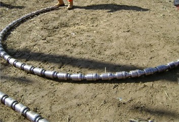
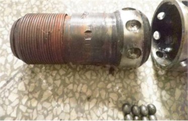
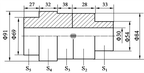
Fig. 1 and Fig. 2 show a hinged flexible drilling tool and a flexible short joint structure. The ball stud key is located within the ball connecting rod groove, forming a universal hinged joint structure. The dimensions of the groove and the ball stud key determine the relative angular displacement between the two sections of the flexible drill string. All dimensions in the figure are in millimeters.
Considering that flexible drill string is an elongated structure exhibiting strong nonlinear behaviors, such as contact and disengagement between its components, adopting solid element modeling in the overall model would result in extremely low computational efficiency and make it difficult to run and solve. Therefore, enhance computational efficiency while considering the structural and stress characteristics of flexible drill string, certain assumptions are made for its modeling.
Assuming the following conditions:
1. Simplifying each component of the flexible drill string as beams with corresponding cross-sections.
2. Simplifying the connection between the ball housing retaining cap, ball stud key and ball connecting rod as a universal joint connection (with controllable relative angular displacement).
3. Disregarding contact friction and hinge clearance, treating it as an ideal hinge. The simplified structure, as shown in Fig. 3, has the hinge located between cross-section S2 and cross-section S3.
Fig. 1Flexible drill string structure
a) Flexible drill string overall structure
b) Hinge joint
Fig. 2Flexible short section construction: 1 – upper ball housing; 2 – bearing housing; 3 – rolling bearing; 4– ball housing retaining cap; 5 – ball stud key; 6 – ball connecting rod
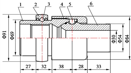
Fig. 3Simplified flexible short section structure
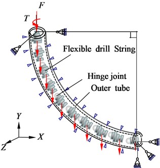
To investigate the stress-strain state and load transfer characteristics of the flexible drill string with different hinge rotation limits, we will focus on studying the inclined section of the flexible drill string and the outer tube as the research objects. The radius of curvature of the inclined section wellbore is 3.2 m. The elastic modulus of the flexible drill string is 210 GPa, the Poisson’s ratio is 0.3, and the density is 7850 kg/m3. The outer diameter of the outer tube is 110 mm, and the inner diameter is 95 mm. The coefficient of friction between the flexible drill string and the outer tube is assumed to be 0.3. The boundary conditions are as follows: the outer tube is fully constrained, the lateral displacement of the upper end of the flexible drill string is constrained, and the lower end of the flexible drill string is constrained in terms of linear displacement and rotational displacement direction. The interface between the flexible drill string and the outer tube is in a frictional contact boundary. The flexible drill string is subjected to a torque of 2000 N·m, an axial force of 20 kN and its own weight. Assuming that the initial state of the flexible drill string is such that its axis lies within the XY plane, the mechanical model of the flexible drill string inside the outer tube is shown in Fig. 4.
Fig. 4Mechanical model of flexible drill string in outer tube
3. Finite element models
The bending of the flexible drill string is achieved through hinges. Based on the structural characteristics of hinges in flexible drill strings, each flexible short joint is considered which composed of five 3D straight beam elements of corresponding structural dimensions. Considering the universal rotation characteristics of flexible drill string hinge connection, the universal joint element is used to describe its rotation. The random contact between the flexible drill string and well wall during movement deformation is accounted for by characterizing beam-beam contact using a contact element.
3.1. Universal joint connection element
The universal joint connection element has two coincident nodes and two relative rotational degrees of freedom, enabling “universal rotation” connection. Fig. 5 depicts the geometry and node positions of the element. Nodes I and J coincide in location, and at both nodes, local Cartesian coordinate systems need to be defined. The directions of the local coordinate systems follow the right-hand rule, and the local coordinate axis y aligns with the main axis of the universal joint.
Fig. 5Coordinates of the universal joint connection element
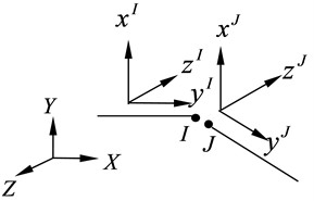
Based on the coordinate system at the nodes of this element, it is relatively easy to describe the motion constraints. The displacement constraint of the universal joint element at any given time is represented by δI=δJ, and the rotational constraint is represented by exI⋅ezJ=0.
The first Cardan angle (rotation around the x-axis) and the third Cardan angle (rotation around the z-axis) of the relative position of node I with respect to node J in the local coordinate system [24] are respectively given by Eq. (1):
The changes of the relative rotation angle of the two local coordinate systems Δφ and Δψ can be represented as Eq. (2):
By combining the beam elements with the universal joint connection elements, and going through the process of coordinate transformation and assembly, we can derive the overall equilibrium equation for the flexible drill string with hinges as Eq. (3):
where, F0 is the node force vector of flexible drill string, N; K0 is the global stiffness matrix of flexible drill string, N/m; δ0 is the node displacement vector of flexible drill string, m.
3.2. Gap element method for nonlinear analysis of beam-to-beam contact
3.2.1. The basic idea of the gap element
The basic idea of the gap element method is to treat the gap between contacting bodies as a virtual element, merging the gap and the contacting bodies into a single entity [25-26]. In three-dimensional beam-to-beam contact problems, the geometric shape of the gap element is circular, with its thickness approaching zero. The stiffness of this virtual element needs to be adjusted based on the specific contact conditions.
The gap element possesses the following physical characteristics:
(1) When the flexible drill string is not in contact with the outer tube, it does not affect the free movement of the flexible drill string, and the compression stiffness approaches zero.
(2) When the flexible drill string is in contact with the outer tube, its compression stiffness is either a given value or becomes sufficiently large. It can resist mutual intrusion of objects while allowing the flexible drill string to move under the conditions of frictional resistance.
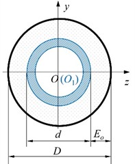
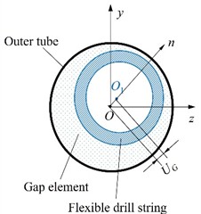
The inner edge of the gap element is in contact with the outer surface of the flexible drill string, meaning that the inner diameter of the gap element is equal to the outer diameter d of the flexible drill string. The outer edge of the gap element is connected to the inner surface of the outer tube, which means that the outer diameter of the gap element is equal to the inner diameter D of the outer tube. As shown in Fig. 6, the orthogonal coordinate system yOz is aligned with the local coordinate system of the beam element. The initial gap Eoi of the gap element i in any direction n can be expressed as Eq. (4):
The deformation of gap element in the n-direction is described UGi as Eq. (5):
where, vi is the displacement of the i node of the flexible drill string along the local axis y, m; wi is the displacement of the i node of the flexible drill string along the local axis z, m.
The strain of the gap element can be represented as Eq. (6):
Fig. 6Schematic diagram of different contact states of the gap element
a) The initial state
b) The compressed state
c) The contact state
3.2.2. Gap element contact state determination
There are two states between the flexible drill string and the outer tube:
1. Free state: The flexible drill string is detached from the outer tube and has no contact with it.
2. Contact state: The flexible drill string is in contact with the outer tube along a certain direction on the circumference, specifically leaning against the inner wall of the outer tube.
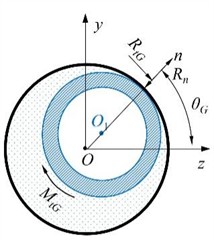
The calculation formula for the normal reaction force Rn generated by the gap element when the flexible drill string is in contact with the outer tube is as Eq. (7):
where, KP is the stiffness of the gap element, N/m; εni is the normal strain of gap element i in any direction n.
The contact azimuth angle θGi of the gap element can be used to describe the random contact of the flexible drill string with the outer tube in the circumferential direction. It can be represented as Eq. (8):
The value of k is determined by the positive or negative of vi and wi [27].
The contact state identification condition expressed by the normal strain, stiffness and contact reaction of the gap element is as Eqs. (9-10).
Free state:
where, εn0, Rn0, KP0 are all positive infinitely small quantity.
Contact status:
According to elasticity theory, the elastic potential energy of any gap element i can be represented as Eq. (11):
Given C1=Eoi⋅KP⋅Eoi, B1=1/Eoi, the potential energy is Eq. (12):
In order to seamlessly integrate the gap element and beam element, the matrices C1 and B1 should be extended with zeros to match the dimension of the nodal dis-placement of the beam element, resulting in square matrices of size 6×6. The elastic potential energy of the gap element can be rewritten as Eq. (13):
where, εΤ1 is the transpose the strain vector of the gap element; δei is the generalized displacement vector of the bottom i node of the flexible drill string, m.
By the variation of Eq. (13), the balanced equation of the gap element can be obtained Eq. (14):
By combining the beam element, universal joint element, and gap element, through the process of coordinate transformation and assembly, we can obtain the overall equilibrium equation for the contact nonlinearity of the flexible drill string with hinged in outer tube. The equation can be expressed as Eq. (15):
where, K0 is the global stiffness matrix of flexible drill string, N/m; KG is the stiffness matrix of contact, N/m; δ is the node displacement of flexible drill string, m; F0 is the joint force vector of flexible drill string, N; FG is the force vector of contact, N.
4. Dynamic relaxation method
When solving the nonlinear Eq. (15), because the hinge can only rotate at a certain angle in two directions, when the rotation limit is not reached, the hinge cannot transmit the bending moment, and its motion is the mechanism motion, when the rotation limit is reached, its motion transitions from the mechanism problem to the structural problem, and due to the randomness of the hinge motion and the unstable articulation connection state, the beam produces rigid body displacement, which is easy to lead to convergence difficulties. In addition, in the same iteration step, it is necessary to complete not only the judgment of the degree of rotation of the universal joint element and the modification of the motion constraint, but also the discrimination and modification of the contact state, until all these conditions are satisfied, so that the generalized displacement and internal forces of the solved beam element can converge to the exact solution.
In order to solve the convergence difficulties and algorithmic instability in the deformation process of the flexible drill string with hinged in outer tube, the dynamic relaxation method is proposed [28]. By applying the method of virtual damping in the dynamic relaxation method, the oscillations in the dynamic problem are quickly eliminated, resulting in a solution that satisfies the static equilibrium equations. The static contact system of Eq. (15) is transformed into a virtual dynamic solution Eq. (16):
In finite element analysis, it is common to assume that the damping matrix C is proportional to either the mass matrix M or the stiffness matrix K. Sometimes, it is also considered as a linear combination of M and K. Due to the fact that the stiffness matrix K is continuously changing during the calculation process, the author has chosen to set a relatively large value for the mass damping coefficient α in the Rayleigh damping to attenuate the dynamic response of the system. By setting α=1000, the damping matrix C=αM and damping force C˙δ=αM˙δ can be determined. When the motion velocity of the flexible drill string is faster, the damping force becomes larger. This helps effectively control sudden changes in the contact state and contributes to improving computational efficiency and stability.
In the nonlinear dynamic Eq. (16), the internal load is no longer directly proportional to the nodal displacements. The stiffness matrix of the flexible drill string depends on the current displacement. Therefore, the Newmark [29] method is used to solve it, and Eq. (16) can be rewritten as Eq. (17):
Assuming a time increment of Δt, the Eq. (17) at time t+Δt can be rewritten as Eq. (18):
where Fit+Δt depends on the current displacement δt+Δt at time t+Δt. Within a time interval Δt Eqs. (19-20):
The input method for the Newmark integration parameters is as follows Eq. (21):
The Newmark method is unconditionally stable [28]. Let γ= 0.005 be used to control the numerical decay factor. Using the Newton-Raphson method, Eqs. (18) to (20) can be simultaneously solved. When the external load does not change with time, Eq. (18) can be expressed as Eq. (22):
As the iteration process continues, the flexible drill string gradually approaches stability, and the deformation δ gradually becomes constant. When ˙δ, ¨δ and FR approach zero, we can obtain F=Fi. According to Eq. (16), we can obtain the static equilibrium state of the flexible drill string constrained by the outer tube.
5. Model verification
5.1. Theoretical analysis of the contact plane model between hinged beam and outer beam
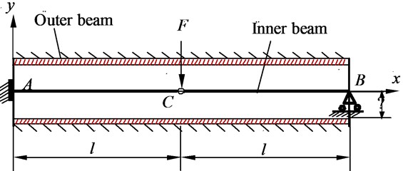
In order to validate the correctness of the model for flexible drill string inside an outer tube and the dynamic relaxation method, a study object was selected consisting of a controllable hinged inner beam and an outer beam. The inner beam has an elastic modulus of E, a diameter of D1, a moment of inertia of I, and a length of 2l. The controllable hinge has a rotational limit ofβ. There is a gap of Δ between the inner beam and the outer beam. The left end of the inner beam is fully fixed, while the right end is supported by a movable hinge support. The outer beam is fully fixed, as shown in Fig. 7.
Fig. 7Plane model for the contact of hinged beam and outer beam
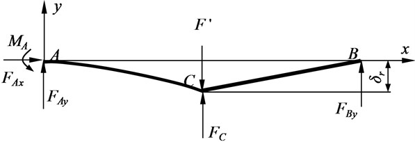
Let’s assume that when the hinge point of the inner beam reaches its rotational limit, the critical concentrated force at that point is denoted as Fr. The internal forces acting on the inner beam are shown in Fig. 8. FAx, FAy and MA represent the support reactions and the reaction couple at point A, while FBy represents the support reaction at point B.
Fig. 8Inner beam force diagram when hinge reaches rotation limit
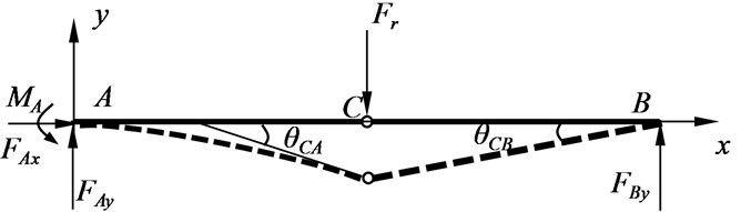
The deflection of the AC segment and the BC segment is represented yFr1 and yFr2 respectively. Based on the equilibrium equation and boundary conditions, the equations representing the angular rotation and deflection of the AC segment and BC segment of the internal beam are as follows Eqs. (23-24).
For the AC segment:
where, E is the Young modulus.
For the BC segment:
The angles at point C of the beams in section AC and section BC are respectively θCA and θCB, and the relative angles β at the hinge can be expressed as Eq. (25):
Let E=2.1×10¹¹Pa, D1= 10mm, I=7.84×10⁻⁹m4, l= 1 m, and the rotational limit of the hinge is β= 1°. According to Eq. (25), when Fr= 34.48 N, the deflection at the hinge point under the action of Fr is denoted as δr:
To ensure that the hinge point of the internal beam reaches the rotational limit before making contact with the outer beam, the following conditions should be met: F>Fr and Δ >δr. Therefore, taking F= 80 N and Δ = 8 mm. According to the principle of superposition, we can split F into two parts, Fr and F', such that F=Fr+F'. The deflection or angular rotation of a specific section of the internal beam under the action of F is equal to the superposition of the deflection or angular rotation under the individual actions of Fr andF'. When Fr reaches the rotational limit, the hinge joint becomes a rigid connection at the internal beam joint. The internal beam transforms into a hyperstatic structure. Under the influence of F', the deflection at point C increases, coming into contact with the outer beam. Additionally, the hinge joint is capable of transmitting bending moments. Remove the restraint of the inner beam of the B end support and replace it with FBy The contact boundary constraint of the outer beam and the internal beam is replaced by FC. The internal beam is subjected to the forces and constraints as shown in Fig. 9.
Fig. 9Inner beam force diagram
The deflection of the AC segment of the internal beam under the separate actions of F' and FC is represented by yF'1 and yFC1 respectively. The deflection of the BC segment of the internal beam under the separate actions of F' and FC is represented by yF'2 and yFC2 respectively. The deflection of the internal beam under the sole action of FBy is denoted by yFBy. Based on the continuity conditions at point C and the conditions of zero angular rotation and deflection at fixed end A, the expressions for the deflection equations can be derived. The total deflection of the internal beam, denoted as yZ, is equal to the algebraic sum of Fr, yF', yFC andyFBy. The inner beam and the outer beam are in contact at x=l, then Eq. (27):
Due to the constraint of the internal beam at point B in the y-direction, the total deflection at point B should be zero. Therefore, the compatibility equation can be expressed as follows Eq. (28):
From this, we can obtain the following Eqs. (29-30):
After determining FC and FBy, the internal beam transforms into a cantilever beam. Based on the equilibrium conditions, we can determine the support reactions at the A end of the internal beam, denoted as FAy and the moment reaction, denoted as MA, as well as the bending moment at point C, denoted as MC Eqs. (31-33):
5.2. Model verification
The flexible drill string model and dynamic relaxation method were used to analyze the contact plane model between the hinged inner beam and the outer beam. The function expression of the lateral force with respect to time is as follows Eq. (34):
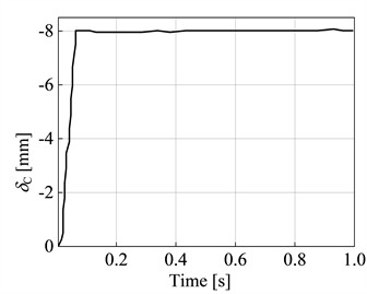
It should be noted that the controllable universal hinge is capable of rotating in two directions. In order to achieve planar hinge rotation that occurs only within the XY plane, in numerical analysis, the first Cardan angle can be constrained to prevent its rotation. Through analysis, the constraint reactions at the A end of the internal beam, denoted as FAy (constraint force) and MA (constraint moment), can be determined as shown in Fig. 10(a) and Fig. 10(b) respectively. The constraint reaction at the B end of the internal beam, denoted as FBy, is shown in Fig. 10(c). The deflection at the hinge point C as a function of time is depicted in Fig. 10(d).
From Fig. 10, it can be observed that during the time interval of 0 to 0.45 s, the support reactions FAy and MA at the fixed end A of the internal beam, as well as the support reaction FBy at point B, exhibit significant fluctuations. The deflection δC at the hinge point C shows relatively small fluctuations, while FAy, MA, FBy, and δC all tend to reach a balanced and stable state when t > 0.45 s. Compared the theoretical analysis and numerical analysis results of the support reactions, moment reactions, contact forces, deflections, and bending moments at the constraint locations of contact plane model of outer beam with internal controllable hinged inner beam. The comparison can be seen in Table 1.
Fig. 10Variation curves of different parameters with time
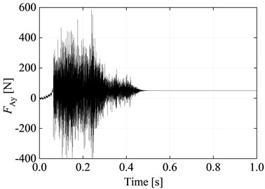
a) Curve of restraining force FAy at point A with time
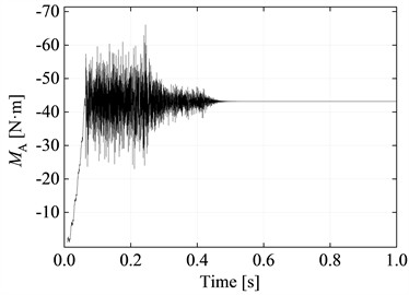
b) Curve of the restraining moment MA at point A with time
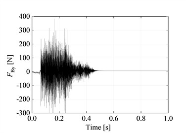
c) Curve of restraining force FBy at point B with time
d) Curve of deflection δC at point C with time
The numerical solution compared to the results obtained from theoretical derivation shows a maximum error of only 0.14 %, confirming the feasibility of flexible drill string with hinged in outer tube model and the dynamic relaxation method (Table 1).
Table 1Comparison of numerical and theoretical solutions
F [N] | Category | FAy[N] | MA[N·m] | FBy[N] | MC[N·m] | δc [mm] | FC[N] |
80 | Theoretical solutions | 50.34 | –43.12 | 7.21 | 22.45 | –8.00 | 50.34 |
Numerical solutions | 50.38 | –43.18 | 7.20 | 22.42 | –8.00 | 50.38 | |
Error / % | 0.08 | 0.14 | 0.14 | 0.13 | 0.00 | 0.08 |
6. Calculation results and analysis
6.1. Analysis of results for different hinge rotation limit results
The dynamic relaxation method is employed to analyze the contact nonlinearity of the flexible drill string with hinges. The functional expressions of the applied torque and axial force at the top of the flexible drill string as a function of time are given as follows Eqs. (35-36):
By conducting a contact nonlinearity analysis on the flexible drill string with hinges, we obtained the torque and axial force variations at the bottom of the flexible drill string for different hinge rotation limits, as shown in Fig. 11.
Fig. 11Variation curve of internal force at the bottom of flexible drill string with time
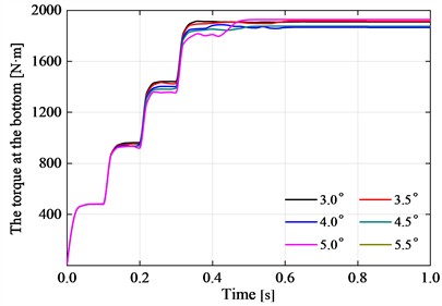
a) The torque at the bottom

b) The axial force at the bottom
According to Fig. 11(a), it can be seen that when t is in the range of 0 s to 0.4 s, the torque applied at the top end of the flexible drill string gradually increases, and the torque at the bottom end shows an increasing trend. After 0.4 s, the torque applied at the top end of the flexible drill string remains constant. The torque at the bottom end reaches an equilibrium and stable state after 0.6 s. The torque at the bottom end of the flexible drill string with different hinge rotation limits degree does not vary significantly. According to Fig. 11(b), it can be observed that when t is in the range of 0 s to 0.4 s, the axial force applied at the top end of the flexible drill string gradually increases, the bottom axial force of the flexible drilling string is showing an overall increasing trend. After 0.4 s, the bottom axial force of the flexible drill string, with a hinge rotation limit of less than 4.5°, reaches a balanced and stable state after more than 0.7 seconds. The bottom axial force of a flexible drill string with a hinge rotation limit greater than or equal to 4.5° reaches a balanced and stable state after more than 0.5 seconds. As the hinge rotation limit increases, the axial force transmitted to the bottom of the flexible drill string gradually decreases. When t= 1 s, both the torque and axial force at the bottom of the flexible drill string have reached a balanced and stable state.
When t=1 s, the calculation results for the different hinge rotational limits degree of the flexible drill string are shown in Table 2. The variations of torque and axial force along the axis of the flexible drill string are illustrated in Fig. 12.
Based on Table 2 and Fig. 12(a), it can be observed that the torque of the flexible drill string decreases gradually as the length along the axis increases. As the hinge rotation limit increases, the torque values of the flexible drill string exhibit larger fluctuations. The total resistance torque between the flexible drill string and the outer tube also increases. However, the variation of torque at the bottom end of the flexible drill string is irregular and does not differ significantly. This is due to the presence of hinges in the flexible drill string, some of which increase torque while others decrease it. As a result, the maximum torque loss rate is only 6.77 %. When the hinge rotation limit is 3.0°, the torque transmitted to the bottom of the flexible drill pipe is 1907.6 N·m, and the torque loss rate is 4.6 %. Compared with the calculation results in reference [30], the torque loss rate is 3.4 % higher. This is because the paper considers the relative rotation characteristics of the flexible drill pipe articulated, resulting in increased deformation of the flexible drill pipe and increased frictional torque between the flexible drill pipe and the outer pipe, so the torque transmitted to the bottom is relatively smaller and the torque loss rate is greater.
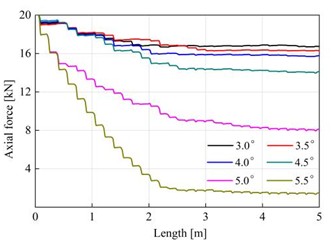
Based on Table 2 and Fig. 12(b), it can be observed that the axial force of the flexible drill string decreases gradually as the length along the axis increases. The decreasing trend of axial force in the flexible drill string is more pronounced within the length range of 0 m to 2.2 m. The decreasing trend of axial force in the flexible drill string is relatively gentle within the length range of 2.2 m to 5.0 m. As the hinge rotational limit increases, the total frictional resistance between the flexible drill string and the outer tube becomes greater. This results in a smaller axial force transmitted to the bottom end of the flexible drill string. When the hinge rotational limits degree are 5.0° and 5.5°, the axial forces transmitted to the bottom end of the flexible drill string are 8.1 kN and 1.5 kN, respectively. The axial force loss rates are 59.5 % and 92.5 %, respectively.
Table 2Calculated results for flexible drill strings with different hinge rotation limits
Hinge rotation limit [°] | Total frictional moment between flexible drill string and outer tube [N·m] | Total frictional resistance between the flexible drill string and the outer tube [kN] | Bottom end torque [N·m] | Bottom end axial force [kN] | Torque loss rate [%] | Axial force loss rate [%] |
3.0 | 75.3 | 5.0 | 1907.6 | 16.7 | 4.6 | 16.5 |
3.5 | 79.3 | 5.2 | 1913.9 | 16.3 | 4.3 | 18.5 |
4 | 83.0 | 5.5 | 1864.7 | 15.8 | 6.7 | 21.0 |
4.5 | 101.5 | 6.7 | 1874.3 | 14.1 | 6.3 | 29.5 |
5 | 198.9 | 13.1 | 1901.9 | 8.1 | 4.9 | 59.5 |
5.5 | 240.9 | 15.9 | 1925.5 | 1.5 | 3.7 | 92.5 |
Fig. 12Torque distribution and axial force distribution of flexible drill string
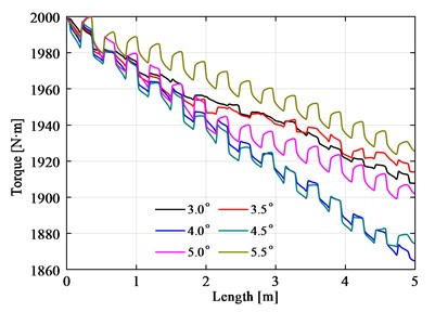
a) Torque distribution
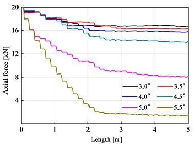
b) Axial force distribution
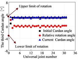
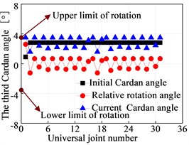
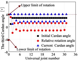
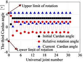
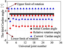
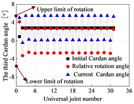
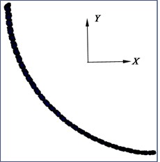
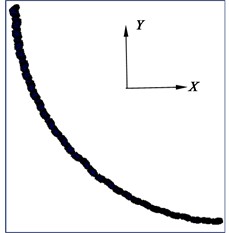
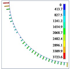
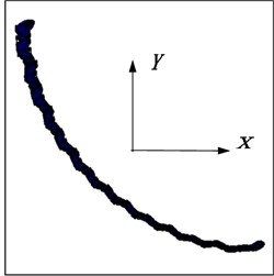
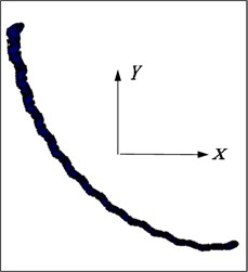
The third Cardan angle at the hinge point of the flexible drill string is illustrated in Fig. 13. The deformation of the flexible drill string in the XY plane is depicted in Fig. 14. Based on Fig. 13 and Fig. 14, it can be observed that as the hinged rotational limit increases, the relative angle of the third Cardan angle at the hinge point of the flexible drill string becomes larger. This results in a more pronounced “sawtooth-like” deformation of the flexible drill string in the XY plane. That is because the flexible drill string utilizes hinges to meet the bending requirements for creating short-radius horizontal wellbore sections. When the wellbore curvature radius is constant, for different hinge rotational limits degree, the initial third Cardan angle at the same hinge point of the flexible drill string is equal and approximately 2.83°. Currently, the upper limit of the third Cardan angle has reached the hinged rotational limit, and the current third Cardan angle is equal to the sum of the initial third Cardan angle and the relative angle of rotation. Therefore, as the hinged rotational limit increases, the relative angle of rotation of the third Cardan angle at the hinge point of the flexible drill string becomes larger.
Fig. 13Third Cardan angle at the hinge of the flexible drill string
a) 3.0°
b) 3.5°
c) 4.0°
d) 4.5°
e) 5.0°
f) 5.5°
Fig. 14Deformation diagram of flexible drill string in XY plane
a) 3.0°
b) 3.5°
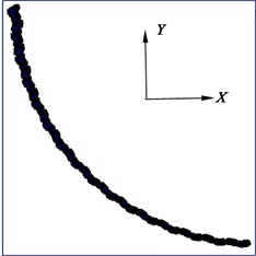
c) 4.0°
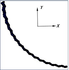
d) 4.5°
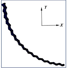
e) 5.0°
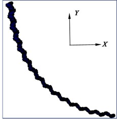
f) 5.5°
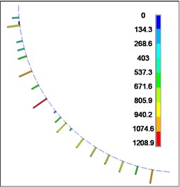
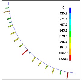
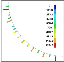
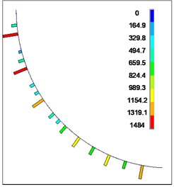
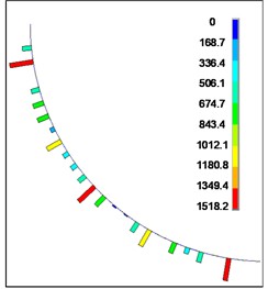
The contact force between the flexible drill string and the outer tube is shown in Fig. 15. According to Fig. 15, it can be observed that the contact force between the flexible drill string and the outer tube is randomly distributed along the axial direction. The contact force is discontinuous and intermittent. This is because the flexible drill string is treated as a variable cross-section beam. Therefore, only the flexible drill string at the maximum cross-section comes into contact with the outer tube. As the hinged rotational limit increases, the maximum contact force between the flexible drill string and the outer tube also increases.
Fig. 15Contact forces between flexible drill string and the outer tube
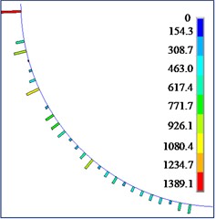
a) 3.0°
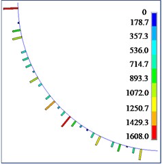
b) 3.5°
c) 4.0°
d) 4.5°
e) 5.0°
f) 5.5°
6.2. Analysis of results for different single section lengths
Through a nonlinear contact mechanics analysis of the flexible drill string with hinges of different single section lengths inside the outer tube, the curves of torque and axial force variations over time at the bottom end of the flexible drill string are obtained. These curves are illustrated in Fig. 16.
Fig. 16Variation curve of internal force at the bottom of flexible drill string with time
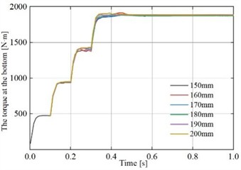
a) The torque at the bottom end
b) The axial force at the bottom
According to Fig. 16(a), it can be observed that from t=0 s to 0.4 s, as the torque applied at the top end of the flexible drill string gradually increases, the torque at the bottom end shows an increasing trend. After 0.4 s, the torque applied at the top end of the flexible drill string remains constant, and the torque at the bottom end reaches a steady state after 0.5 s. The torque at the bottom end of the flexible drill string does not differ significantly for different single section lengths. According to Fig. 16(b), it can be observed that from t=0 s to 0.4 s, as the axial force applied at the top end of the flexible drill string gradually increases, the axial force at the bottom end of the flexible drill string shows an overall increasing trend. After 0.6 s, the axial force at the bottom end of the flexible drill string for different single section lengths reaches a steady state. The flexible drill string with a single section length of 200 mm experiences the highest transmitted axial force at the bottom end, while the flexible drill string with a single section length of 150 mm experiences the lowest transmitted axial force at the bottom end.
Overall, the transmitted axial forces at the bottom end of the flexible drill string do not differ significantly for different single section lengths.
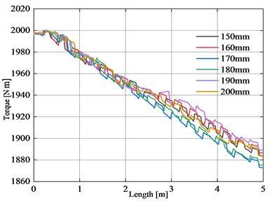
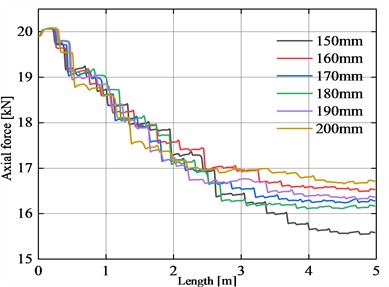
When t=1 s and the hinged rotational limit is 4.0°, the calculated results for different single section lengths of the flexible drill string are presented in Table 3. The variations of torque and axial force along the axis of the flexible drill string are illustrated in Fig. 17.
Table 3Calculated results of flexible drill string with different single section lengths
Single section length [mm] | Total frictional moment between flexible drill string and outer tube [N·m] | Total frictional resistance between the flexible drill string and the outer tube [kN] | Bottom end torque [N·m] | Bottom end axial force [kN] | Torque loss rate [%] | Axial force loss rate [%] |
150 | 56.8 | 3.8 | 1901.6 | 15.6 | 4.9 | 22.0 |
160 | 57.7 | 3.8 | 1917.3 | 16.5 | 4.1 | 17.5 |
170 | 59.5 | 3.9 | 1886.5 | 16.4 | 5.7 | 18.0 |
180 | 58.8 | 3.9 | 1883.1 | 16.3 | 5.8 | 18.5 |
190 | 63.8 | 4.2 | 1892.1 | 16.4 | 5.4 | 18.0 |
200 | 65.3 | 4.3 | 1913.3 | 16.7 | 4.3 | 16.5 |
Fig. 17Distribution of internal forces along the axis of flexible drill string
a) Torque distribution
b) Axial force distribution
Combining Table 3 and Fig. 17(a), it can be observed that the torque of the flexible drill string exhibits a generally decreasing trend along the length of the axis. When the single section length varies, the total frictional resistance torque between the flexible drill string and the outer tube exhibits irregular changes. However, the torque values transmitted to the bottom end of the flexible drill string do not differ significantly. The maximum torque loss rate is only 5.84 %.
Based on Table 3 and Fig. 17(b), it can be observed that the axial force of the flexible drill string exhibits an overall decreasing trend along the length of the axis. The decreasing trend of the axial force in the flexible drill string is more pronounced in the length range of 0 m to 3.2 m. The decreasing trend of the axial force in the flexible drill string is relatively gradual in the length range of 3.2 m to 5.0 m. There is not a significant difference in the axial force at the bottom end of the flexible drill string for single section lengths greater than 150 mm.
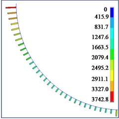
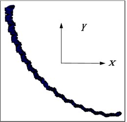
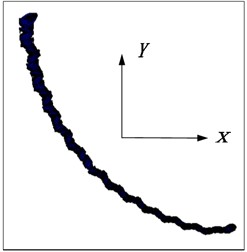
The deformation of the flexible drill string in the XY plane is illustrated in Fig. 18. According to Fig. 19, it can be observed that as the single section length decreases, the “sawtooth-like” deformation of the flexible drill string in the XY plane becomes more pronounced. This is because with smaller single section lengths, the relative angular displacement at the joints of the flexible drill string becomes larger.
Fig. 18Deformation diagram of flexible drill string in XY plane
a) 150 mm
b) 160 mm
c) 170 mm
d) 180 mm
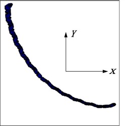
e) 190 mm
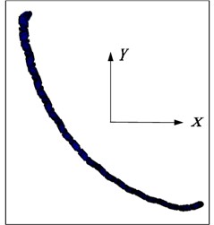
f) 200 mm
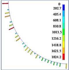
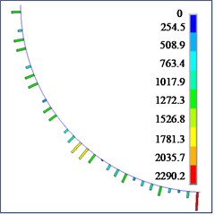
Fig. 19Contact force between flexible drill string and outer tube
a) 150 mm
b) 160 mm
c) 170 mm
d) 180 mm
e) 190 mm
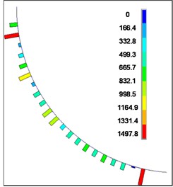
f) 200 mm
The contact forces between the flexible drill string and the outer tube are depicted in Fig. 19. According to Fig. 19, it can be observed that the contact forces between the flexible drill string and the outer tube are randomly distributed along the axial direction. The contact forces exhibit intermittent and discontinuous behavior. As the length of the flexible drill string increases, the maximum contact force between the flexible drill string and the outer tube initially increases and then decreases.
7. Conclusions
1) Considering the transitional problem between the mechanism and structure of a flexible drilling string with hinges, and the non-linear characteristics of contact, a finite element model of the contact non-linearity finite element model of flexible drill string inside the outer tube was established by combining spatial beam elements, universal joint connection element, and gap elements. The model enables the universal rotation and angle control of the hinge connection, thereby providing a more accurate representation of the stress and deformation characteristics exhibited by flexible drill strings. The dynamic relaxation method is proposed to solve the beam-beam contact nonlinear problem. By increasing the mass damping coefficient, the kinetic energy generated by the system is dissipated and the system is accelerated to a stable state.
2) According to the superposition principle and the deformation compatibility condition, the expressions for the deflection, bending moment, and contact force at the hinge joint of the outer beam and internal hinged beam under the application of a transverse load are derived. The numerical analysis of the above-mentioned planar model is conducted using the non-linear contact model of flexible drill string inside the outer tube and the dynamic relaxation method. The numerical analysis results obtained are compared with the theoretical solution, and the maximum error is only 0.14 %. The feasibility of the contact model and numerical calculation method of the flexible drill string with hinges inside the outer tube is verified.
3) By conducting contact nonlinear mechanical analysis on six hinged drill strings with rotational limits in the inclined section, the contact force between the flexible drill string and the outer pipe is randomly distributed along the axis direction. The contact force is discontinuous. Through the contact non-linear mechanics analysis of the hinged drilling string with six different hinge rotation limits in the inclined section, the contact force between the flexible drill string and the outer tube is randomly distributed along the axis direction. As the hinge rotation limit increases, the total frictional resistance and total frictional torque between the flexible drill string and the outer tube gradually increase. The torque transmitted to the bottom of the flexible drill string does not change much, but the axial force transmitted to the bottom of the flexible drill string gradually decreases. The maximum torque loss rate is only 6.77 %. When the hinged rotation limit is 5.0°, the axial force loss rate reaches 59.5 %. Therefore, when designing a flexible drill string, it is crucial to fully consider the influence of flexibility on the transmission of drill tool loads. The hinged rotation limit of the flexible drill string should be controlled within 5.0°.
4) Through simulation analysis of six different single section lengths of flexible drill strings with a hinged rotation limit of 4.0° in the inclined section, it has been determined that, the contact force between the flexible drill string and the outer tube is randomly distributed along the axial direction, and the contact force is discontinuous. As the length of single section increases, the total moment of friction between the flexible drill string and the outer tube gradually increases. Initially, the total frictional resistance increases, then decreases, and then increases again. The maximum torque loss rate is only 5.84 %, and the maximum axial force loss rate is 22 %. The axial force and torque transmitted by the flexible drill string of different single section lengths to the bottom of the well do not vary significantly.
References
-
W. Dickinson and R. W. Dickinson, “Horizontal radial drilling system,” in SPE California Regional Meeting, Mar. 1985, https://doi.org/10.2118/13949-ms
-
H. P. Chi, G. S. Li, Z. W. Huang, F. Di, and G. W. Tang, “Research status and analysis of hydro-jet radial horizontal well technology,” Drilling Technology, Vol. 36, No. 4, pp. 119–124, 2013, https://doi.org/10.3969/j.issn.1006-768x.2013.04.38
-
R. S. Balch, T. Ruan, M. Savage, and J. Harvard, “Field testing and validation of a mechanical alternative to radial jet drilling for improving recovery in mature oil wells,” in SPE Western Regional Meeting, May 2016, https://doi.org/10.2118/180410-ms
-
D. Jain et al., “Radial jet drilling in mature fields of oil India limited – an experimental approach,” in SPE Oil and Gas India Conference and Exhibition, Apr. 2017, https://doi.org/10.2118/185398-ms
-
M. Bruni, H. Biasotti, and G. Salomone, “Radial drilling in Argentina,” in Latin American and Caribbean Petroleum Engineering Conference, Apr. 2007, https://doi.org/10.2118/107382-ms
-
Y. B. Guo, S. H. Guan, Z. Q. Liu, H. Guo, and X. Y. Liu, “First application of multi-branch ultra-short radius drilling technology in China’s offshore oil fields,” China Offshore Oil and Gas, Vol. 32, No. 5, pp. 137–144, 2020, https://doi.org/10.11935/j.issn.1673-506.2020.05.017
-
J. Y. Qin, H. Y. Xia, Z. Tian, Y. T. Zhang, B. Li, and Y. F. Liu, “Research and application of ultra-short radius horizontal well drilling technology in deep offshore formations,” Petrochemical Industry Application, Vol. 41, No. 6, pp. 21–24, 2022.
-
Y. N. Su and J. P. Zhao, “The establishment and analysis of mechanical model of joint-hinge power BHA in short-radius horizontal well drilling,” Oil Drilling and Production Technology, Vol. 17, No. 4, pp. 25–33, 1995, https://doi.org/http://doi.org/cnki:sun:syzc.0.1995-04-004
-
J. Shuai and C. Liu, “Static analysis of new type of hinged bottom hole assembly,” China Offshore Oil and Gas (Engineering), Vol. 13, No. 5, pp. 35–38, 2001.
-
H. Liu et al., “Application of ultrashort radius lateral drilling technique in top thick reservoir exploitation after long term water flooding,” in Abu Dhabi International Petroleum Exhibition and Conference, Nov. 2016, https://doi.org/10.2118/183231-ms
-
M. Luo, E. Y. Zhao, T. T. Zhao, and T. T. Xu, “Research on ultimate torques of the flexible drill rod for ultra-short radius horizontal wells,” Journal of Northeastern University: Natural Science, Vol. 34, No. S2, pp. 22–25, 2013.
-
H. Y. Wang, C. X. Li, X. Y. Ruan, and R. H. Wang, “Three-dimensional finite element simulation of radial well drill string section deformation,” Journal of Petroleum, Vol. 23, No. 4, pp. 97–101, 2002, https://doi.org/10.3321/j.issn:0253-2697.2002.04.021
-
H. Y. Wang, “Analysis on simulation and experiment of the drill-pipe cross-section deformation of ultra-short radius radial system,” Advanced Materials Research, Vol. 706-708, No. 2, pp. 1213–1217, Jun. 2013, https://doi.org/10.4028/www.scientific.net/amr.706-708.1213
-
H. Y. Wang, P. X. Sun, and Y. C. Liu, “Radial well steering chute introduction section resistance model and its polynomial solution,” Journal of China University of Petroleum: Natural Science Edition, Vol. 31, No. 5, pp. 91–94, 2007, https://doi.org/10.3321/j.issn:1000-5870.2007.05.020
-
X. X. Zhu, Y. P. Xu, W. X. Zhou, G. G. Ye, and B. Zhou, “Research on parameter design method and motion characteristics of a ball cage flexible joint,” Energies, Vol. 15, No. 20, p. 7591, 2022, https://doi.org/http://doi.org/10. 3390 /en15207591
-
Y. Y. Yang, X. Q. Xu, and X. C. Niu, “Key technology for steering and feeding radial horizontal wells with open top window,” Journal of China University of Petroleum: Natural Science Edition, Vol. 38, No. 5, pp. 89–95, 2014, https://doi.org/10.3969/j.issn.1673-5005.2014.05.012
-
S. H. Hou, “Research on radial drilling casing windowing tool,” China University of Petroleum, Beijing, 2018.
-
Y. C. Liu, X. J. Yue, Y. Chen, and J. Liu, “Modeling and simulation of bending steering and resistance of radial horizontal drill pipe,” Journal of Plasticity Engineering, Vol. 13, No. 2, pp. 103–109, 2006, https://doi.org/10.3969/j.issn.1007-2012.2006.02.024
-
Y. C. Liu, X. J. Yue, Y. Chen, and H. Y. Wang, “Simulation study on steering mechanism of ultra-short radius radial horizontal wells,” Journal of China University of Petroleum: Natural Science Edition, Vol. 30, No. 2, pp. 85–89, 2006, https://doi.org/10.3321/j.issn:1000-5870.2006.02.019
-
Z. F. Wang, Z. C. Guan, and W. F. Li, “Analysis of multiphase flow patterns in ultra-short radius horizontal well nozzles,” Journal of Coal, Vol. 36, No. 7, pp. 1098–1101, 2011.
-
J. Li, G. Li, Z. Huang, X. Song, R. Yang, and K. Peng, “The self-propelled force model of a multi-orifice nozzle for radial jet drilling,” Journal of Natural Gas Science and Engineering, Vol. 24, pp. 441–448, May 2015, https://doi.org/10.1016/j.jngse.2015.04.009
-
D. J. Ma et al., “A model for calculating pressure consumption in radial horizontal well circulation system for continuous tubular lateral drilling,” Petroleum Exploration and Development, Vol. 39, No. 4, pp. 494–499, 2012.
-
W. Bin, L. Gensheng, H. Zhongwei, L. Jingbin, Z. Dongbo, and L. Hao, “Hydraulics calculations and field application of radial jet drilling,” SPE Drilling and Completion, Vol. 31, No. 1, pp. 071–81, Mar. 2016, https://doi.org/10.2118/179729-pa
-
S. Shah, S. K. Saha, and J. K. Dutt, “Denavit-Hartenberg parameters of Euler-angle-joints for order (N) recursive forward dynamics,” in ASME 2009 International Design Engineering Technical Conferences and Computers and Information in Engineering Conference, Jan. 2009, https://doi.org/10.1115/detc2009-87017
-
Q. Zhang, Y. Zhu, Z. Xiao, W. Li, W. Cui, and Q. Yue, “On the post-buckling analysis of a circular column with cylindrical constraint under concentrated torque loading,” Ocean Engineering, Vol. 188, p. 106261, Sep. 2019, https://doi.org/10.1016/j.oceaneng.2019.106261
-
Q. Zhang, B. Jiang, Z. Xiao, W. Cui, and J. Liu, “Post-buckling analysis of compressed rods in cylinders by using dynamic relaxation method,” International Journal of Mechanical Sciences, Vol. 159, No. 1, pp. 103–115, 2019, https://doi.org/10.1016/j.ijmecsci
-
J. B. Liu and M. Luo, Finite Element Method and Applications. Beijing: China Electric Power Press, 2013.
-
M. Rezaiee-Pajand and H. Estiri, “Computing the structural buckling limit load by using dynamic relaxation method,” International Journal of Non-Linear Mechanics, Vol. 81, pp. 245–260, May 2016, https://doi.org/10.1016/j.ijnonlinmec.2016.01.022
-
K. J. Bathe, Finite Element Procedures. Pearson Education, Prentice Hall, 2014.
-
X. Zhao, “Mechaniccs analysis and safety evaluation of flexible drill string in ultra short radius horizontal well,” Northeast Petroleum University, Daqing, 2013.
About this article

This research was supported by the Northeast Petroleum University under Grant “National Fund” cultivation fund project (2022GPL-11).
The datasets generated during and/or analyzed during the current study are available from the corresponding author on reasonable request.
Pengyu Sun: formal analysis, and writing-original draft preparation. Tingting Xu: conceptualization, methodology, data curation, awnd writing-review and editing. Qianbei Yue: conceptualization, methodology, supervision.
The authors declare that they have no conflict of interest.
