Abstract
Composite vibration damping is a crucial aspect in enhancing the performance of shock absorber, with potential for significant application in multi-degree-of-freedom sports facilities. Based on the finite element method, the modal analysis, harmonic response analysis and stiffness analysis of metal rubber shock absorber were realized, and the parameters of natural frequency, acceleration transmissibility and average stiffness were verified. Through ABAQUS, the finite element model of shock absorber was established and reasonably simplified, and the influence of wire diameter and relative density on the comprehensive performance was studied under the condition of prestress modal analysis. The results indicate that the shock absorber with a relative density of 0.35 exhibits higher average stiffness, but lower energy dissipation coefficient. Additionally, it shows larger peak values for natural frequency and acceleration transmissibility, but reduced damping. The simulation findings are in line with the experimental results, demonstrating the accurate acquisition of nonlinear mechanics and dynamic response properties of metal rubber shock absorber.
Highlights
- Based on the finite element method, the modal analysis, harmonic response analysis and stiffness analysis of metal rubber shock absorber were realized.
- Through ABAQUS, the finite element model of shock absorber was established and reasonably simplified.
- The influence of wire diameter and relative density on the comprehensive performance was studied under the condition of prestress modal analysis.
1. Introduction
Certain sports fitness equipment incorporates a multi-degree of freedom mechanism, facilitating the generation of substantial impact forces that may detrimentally affect the stability and operational lifespan. The continuous operation of internal machinery in comprehensive sports equipment, along with the contact transmission force load and temperature load between the connected components, will result in significant vibration and impact forces on the engine and body structure. This leads to a continuous external force on the components, which can have detrimental effects on dimensional accuracy, mechanical transfer efficiency, as well as significantly reducing stability, reliability and service life of the actuator. Furthermore, excessive vibration can lead to noise production that may have adverse effects on human physical and mental health. The metal spring damper exhibits good stiffness and strength, however, it does not provide ideal damping for high frequency vibrations. The compound vibration damping device, also named rubber shock absorber, can partially reduce the impact force and high-frequency vibration, but its durability and stability require improvement. The metal rubber shock absorber is capable of addressing these issues by dissipating energy through hysteresis phenomenon when resisting deformation due to its complex internal structure and nonlinear material characteristics. Under the influence of various damping forces, it demonstrates obvious nonlinear characteristics in external force response and vibration response. With the continuous advancement in nonlinear dynamics theory and computer technology, numerical simulation has become an essential tool for studying product and equipment performance.
2. The establishment of finite element model
2.1. Assembly model establishment and simplification
As shown in Fig. 1(a), it is a widely used crossfit equipment with a multi-DOF structure, which is conducive to achieving complex movements. The athlete can realize the force transmission through the lifting and lowering of the counterweight and the composite movement of multiple links. In the conventional structure design, the bottom end of the counterweight is rigid contact between the supports, which will lead to greater noise and vibration, not only affecting the fitness experience, but also not conducive to the life of the equipment. For this purpose, a shock absorber is designed, as shown in Fig. 1(b), and proposed to be applied in the buffer of counterweights. According to the structural principle of the shock absorber, it can fully reduce the impact force and high-frequency vibration, but its internal wire diameter and relative density have a key impact on the overall natural frequency, acceleration propagation and stiffness, which is an important factor in determining the durability and stability of the equipment.
The finite element analysis focuses on studying only the major and key factors in the model. Appropriate simplifications are made for minor structures to ensure calculation accuracy and improve efficiency, without affecting the basic characteristics of the model. A 3D model was created in UG, consisting of seat, shaft, cover, net block, lower net block and square mass. In order to analyze the nonlinear relationship between load and displacement of metal rubber shock absorber and identify system vibration response through numerical simulation analysis, certain features with little influence on the model analysis results can be disregarded. For example, in actual working conditions, the dust ring of the shock absorber is not stressed so it is omitted from modeling process. The thread part of solid shock absorber model is simplified to enhance numerical calculation accuracy and normal grid division within the model.
Fig. 1Structure and composition of shock absorber
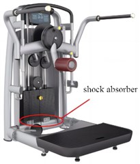
a) Installation location of shock absorber
b) Internal structure of the shock absorber
The mass block is employed to simulate the external load, and the 3D model of the metal rubber damper is imported into ABAQUS for integration. To precisely ascertain the relative positioning of components, the central point of the lower surface of the shock absorber seat serves as the origin of the coordinate axis. This study exclusively concentrates on analyzing the motion of both shock absorber and metal rubber components in their respective vertical working direction; hence coaxial constraints are imposed on each component to prevent any axial movement.
2.2. Preprocessing of the model
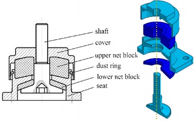
For metal rubber materials, when the shock absorber is subjected to external load, it is the medium of load transmission, under a certain pressure, in a state of compression, and the relationship between force and displacement under the action of pressure shows a certain nonlinear. Based on this property of metal rubber, the nonlinear mechanical behavior of metal rubber materials will be described by the method of self-defining material properties, as shown in Fig. 2. The most commonly used contact in the interaction is “surface to surface contact”, which is mainly set in the normal direction and tangential direction of the contact properties between the opposite and the surface. In the contact analysis, one of the two contact surfaces is the main surface and the other is the slave surface. The main surface is relatively rigid, the grid is sparse, and its nodes can pass through the slave surface. The properties of “surface to surface contact” are set between the upper and lower surfaces of the two metal rubber mesh elements and the inner surfaces of the shock absorber structural components. The normal direction adopts “hard contact” and the tangential direction adopts contact without slip. At the same time, in order to ensure the calculation quality, the component surface with high stiffness is selected as the main surface, that is, the contact surface of the mesh block is the slave surface.
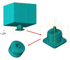
To ensure the accuracy of the calculation of key features, and to prevent the calculation from being unable to be carried out due to abnormal singular elements, the shock absorber parts should be cut before grid division. The characteristics of each part of the shock absorber are analyzed comprehensively, and the non-uniform mesh division is adopted. When the mesh size of the model is large, the mesh division of mass blocks is thicker. The structural components of the shock absorber cover, seat and shaft mesh are the same size. For the metal rubber parts in the core part of the model, seed encryption is carried out to make the grid division more dense, as shown in Fig. 3. The test system consists primarily of a shaking table, vibration control instrument, signal acquisition instrument, power amplifier, charge amplifier, sensor, computer and other devices. During the test process, a signal parameter is configured in the computer. The vibration control system then converts it into an excitation signal which is input into the power amplifier for energy amplification before initiating the operation of the shaking table. Subsequently, two accelerometers transmit back the vibration signals from the shaking table to output test data to the data acquisition system for analysis and processing by computer.
Fig. 2Material constitutive model
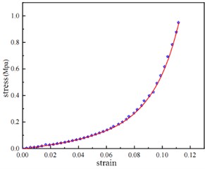
Fig. 3Meshing results
3. Dynamic characteristic analysis
3.1. Modal analysis
Modal analysis is a widely used engineering analysis method, which is based on the theory of vibration mechanics and the finite element method, and can predict the vibration characteristics of the structure in the state of free vibration. For the proposed shock absorber, its operating frequency is mainly low frequency, and the wire diameter and relative density are very sensitive to excitation vibration, so it is necessary to analyze the natural frequency under different parameter conditions based on modal simulation calculation to prevent resonance problems.
The metal rubber shock absorber studied works under the load condition of 400 kg, so the constrained mode analysis is carried out. Combined with the installation mode of the shock absorber on the DC-10000-100 shaking table in the test, the bottom of the shock absorber seat was fully constrained, and the displacement constraint was imposed on the mass block to make it move only in the axial direction. Since the frequency range is within 500 Hz, the frequency analysis step is established, and the feature solver chooses the “Lanczos” calculation method with wide application range, fast operation speed and high calculation accuracy. In order to study the influence of wire diameter and relative density in shock absorber on dynamic characteristics, different models were simulated and tested, and the results were shown in Table 1. In the post-processing analysis module, the first-order frequency of the system represents its natural frequency, which is then compared with the natural frequency of the shock absorber under test conditions, as detailed in Table 1. The largest discrepancy between simulation and test results, at 12.62 %, occurs when the specimen wire diameter is 0.3 mm and relative density is 0.3. Conversely, the model with a diameter of 0.3 mm and a relative density of 0.2 exhibits the smallest simulation error at only about 5 %, making it relatively accurate for most engineering applications.
Table 1Comparison of natural frequency test values with simulated values
No | Wire diameter d / mm | Relative density γ | Calculated value of natural frequency / Hz | Test value of natural frequency / Hz |
1 | 0.3 | 0.25 | 13.39 | 13.30 |
2 | 0.3 | 0.3 | 17.52 | 15.28 |
3 | 0.3 | 0.35 | 27.14 | 26.33 |
4 | 0.2 | 0.3 | 13.37 | 13.75 |
5 | 0.4 | 0.3 | 29.39 | 27.67 |
Fig. 4Natural frequency simulation value and test value comparison diagram
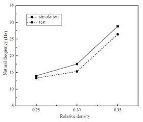
a) Natural frequency at different relative density
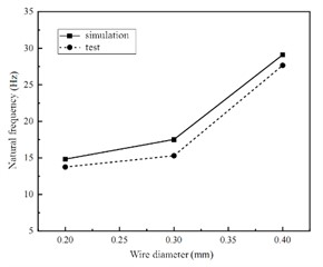
b) Natural frequency at different wire diameter
3.2. Harmonic response analysis
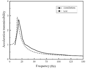
For shock absorber, the significance of harmonic response analysis is to predict the continuous dynamic characteristics of the mechanical structure, which is conducive to assessing the steady state of the linear structure, so as to verify whether the design can overcome the harmful effects caused by forced vibration such as fatigue during long-term operation. Based on the natural frequencies obtained from modal analysis, the harmonic response of metal rubber shock absorber with varying structural parameters is analyzed and computed using the modal superposition method. Initially, a steady-state dynamic analysis step is established based on the modal analysis and set within the 0 to 500 Hz range to align with test settings for facilitating data comparison. Concurrently, in this analytical step, an acceleration base motion with an amplitude of 2 g and load direction along the z-axis is defined, simulating a sinusoidal sweep frequency test on a shaking table. The field output of the entire model is then established in this analytical step, focusing primarily on displacement and acceleration as key output parameters. In the post-processing module, the amplitude of the acceleration response at the midpoint of the upper end face of the mass block is extracted and processed to obtain the acceleration transmission-frequency curve of the vibration reduction system under different structural parameters, as illustrated in Fig. 5.
According to the harmonic response analysis, it can be seen that the simulation results of sweeping frequency are basically consistent with the test results in the trend of change, the phase of the test value is slightly lagging, and the peak point of the simulated value is higher than that of the test value. In other words, compared with the test value, the natural frequency of the simulated value is smaller, the peak value of the acceleration transmittance is larger, and the acceleration transmittance rises faster. Because the output sensor of the test value is located on the side of the mass block, and the acceleration response of each integral point on the mass block is different in the finite element simulation results, the acceleration transmissibility value will be slightly different.
Fig. 5Acceleration transmissibility of shock absorber with different structural parameters
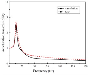
a)d=0.3, γ=0.25
b)d= 0.3, γ=0.23
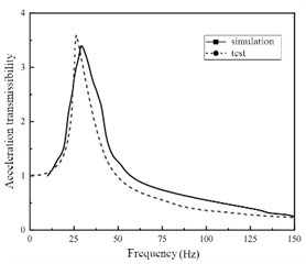
c)d=0.3, γ=0.35
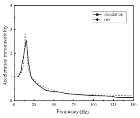
d)d=0.2, γ=0.23
3.3. Stiffness characteristic analysis
The average stiffness is one of the important parameters affecting the damping effect. If the stiffness is too large or too small, it will affect the working effect of the shock absorber, and even intensify the vibration and shaking of the counterweight. Therefore, the average stiffness was simulated and tested for different wire diameters and relative densities.
In the simulation of compression conditions, in conjunction with the setup of a universal testing machine, the square mass block and its related features were disabled in the finite element model of the metal rubber shock absorber, leaving only the metal rubber shock absorber part. The shock absorber will deform when subjected to external loads. When simulating compression conditions, a static analysis step is initiated with geometric nonlinearity enabled. Additionally, a coupling point at the shaft end of the shock absorber is established to obtain process output data for reaction force and displacement. The definition of load is usually defined by specifying boundary conditions or applying an initial displacement. In the initial analysis step, the axial displacement constraint of the metal rubber shock absorber is added and the underside of the seat is completely fixed. In the load analysis step, a load of 4000 N is applied to the upper surface of the shock absorber cover to simulate the loading process.
The average stiffness of the shock absorber is determined through finite element numerical simulation and testing under varying relative densities and wire diameters, as depicted in Fig. 6. It is evident that, under consistent conditions, the average stiffness of the shock absorber simulated by the finite element method exhibits a positive correlation with both relative density and metal wire diameter. This observation further underscores the feasibility of utilizing the finite element method to replicate loading conditions for metal rubber shock absorbers. It also shows that the relative density of metal rubber components is positively correlated with the stiffness and average stiffness of the shock absorber, and negatively correlated with its energy dissipation coefficient, and its stiffness has strong nonlinear.
Fig. 6Average stiffness simulation value and test value comparison diagram
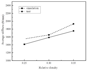
a) Average stiffness at different relative density
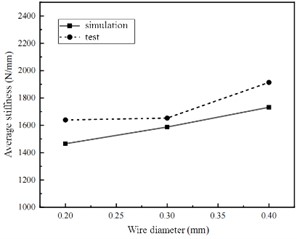
b) Average stiffness at different wire diameter
4. Conclusions
1) According to the structural and performance analysis of the shock absorber, it is evident that the stiffness of the metal wire increases with an increase in wire diameter, making it less susceptible to bending and deformation. Simultaneously, when the relative density remains constant, there is a reduction in contact pairs between wires leading to a decrease in dry friction damping dissipation energy. Consequently, this results in a larger peak acceleration transfer rate and reduced vibration reduction efficiency, ultimately leading to a higher frequency of entering the working state.
2) Under the same vibration order, the stiffness of the specimen increases with the increase of the diameter of the metal wire, and the stiffness of the specimen is also larger. The shock absorber is in the hard characteristic stage, it is not easy to bend and deform in the vibration state, it is difficult to squeeze and slip between the wires, and the dissipated energy is also reduced, so the damping ratio of the shock absorber is also reduced.
References
-
Y. H. Yu, “Modal and harmonic response analysis of a rolling bearing coupled by rigid and flexible materials,” Materials Express, Vol. 9, No. 9, pp. 1017–1024, 2019, https://doi.org/10.1166/ mex.2019.1608
-
A. D. Shaw, G. Gatti, P. J. P. Gonçalves, B. Tang, and M. J. Brennan, “Design and test of an adjustable quasi-zero stiffness device and its use to suspend masses on a multi-modal structure,” Mechanical Systems and Signal Processing, Vol. 152, No. 1, p. 107354, May 2021, https://doi.org/10.1016/j.ymssp.2020.107354
-
M. J. Rezvani and H. Souzangarzadeh, “Performance of end-capped multi-segmented conical tubes filled with foam under axial and oblique loads as an energy absorber,” Journal of the Brazilian Society of Mechanical Sciences and Engineering, Vol. 46, No. 6, pp. 188–198, May 2024, https://doi.org/10.1007/s40430-023-04581-4
-
R. Talebitooti, M. Zarastvand, and H. Darvishgohari, “Multi-objective optimization approach on diffuse sound transmission through poroelastic composite sandwich structure,” Journal of Sandwich Structures and Materials, Vol. 23, No. 4, pp. 1221–1252, Jun. 2019, https://doi.org/10.1177/1099636219854748
-
H. Dong, “Seismic performance assessment of RC bridge piers with variable hysteresis performance dampers,” Engineering Structures, Vol. 12, No. 1, pp. 28–39, 2024, https://doi.org/10.1016/ j.engstruct.2024.118085
-
S. V. Sharma, H. Gladston, and A. Ebanesar, “Effect of piston displacement on performance of an MR damper for structural application,” Practice Periodical on Structural Design and Construction, Vol. 29, No. 3, pp. 102–114, Aug. 2024, https://doi.org/10.1061/ppscfx.sceng-1493
About this article

The authors have not disclosed any funding.
The datasets generated during and/or analyzed during the current study are available from the corresponding author on reasonable request.
The authors declare that they have no conflict of interest.
