Abstract
The vibration mechanism of railways and urban rail transit is highly intricate, particularly within the railway environment. This study employs a variety of vertical stiffness damping pads to develop an integrated damping system for a floating slab. Through optimization of damper stiffness and arrangement, the modal characteristics of the floating slab are analyzed, resulting in a reduction of the inherent frequency of the track structure and attenuation of vibration transmission. Subsequently, this damping system is implemented in an actual engineering project to assess its effectiveness. The findings indicate that lower stiffness in the vibration isolation pad corresponds to a smaller inherent frequency for the floating slab, thereby enhancing its damping efficacy. Utilizing elastic supports for vibration isolation pads within the track structure can mitigate upper structure vibrations induced by trains.
Highlights
- Develop an integrated damping system for a floating slab.
- Modal characteristics of the floating slab are analyzed.
- Utilizing elastic supports for vibration isolation pads can mitigate upper structure vibrations.
1. Introduction
The vibration mechanism of rail and urban rail transit, as exemplified by the railway environment, is intricate, with its effects influenced by various factors including vehicles, tracks, substructures beneath the tracks, infrastructure, soil, and buildings along the route [1]. Environmental vibrations induced by rail transit systems can be categorized into three components: the source (vehicles, tracks, and supporting foundation structures), the transmission path (soil), and the receptor (buildings) [2]. The generation of rail transit environmental vibrations stems from the impact of wheel sets on the tracks during train operation leading to vibrations in both vehicle and track structure [3]. These vibrations are then transmitted through substructures beneath the tracks and infrastructure (such as bridges, subgrade elements, tunnels) to surrounding soil where they propagate outwardly causing secondary vibrations in nearby buildings.
Some research has been conducted on these three subsystems [4], focusing on the generation mechanism of vibrations, the key parameters affecting vibrations in track and infrastructure, the transmission of vibrations, and related control measures. The research methods employed primarily include theoretical approaches, numerical simulations, experiments, and empirical analyses [5]. Theoretical methods typically entail mathematical and mechanical derivations; however, due to the complexity of rail transit vibration systems, there are numerous simplifications in theoretical calculations with idealized boundary conditions and material parameters. Their applicability is limited. Numerical methods utilize simulation models such as finite element analysis and multi-body dynamics to solve vibrations with broader applicability but longer computation times and higher technical expertise requirements [6]. Experimental methods offer a more direct reflection of rail transit-induced vibration conditions but are constrained by test factors and operational conditions making it challenging to encompass all boundary scenarios while being time-consuming and costly [7]. Empirical methodologies generally derive relevant formulas from experimental results fitting within an experimental framework [8].
The development of railway integrated complexes above ground is still in its early stages, with limited actual engineering cases and corresponding standard specifications and research results, posing significant challenges to the initial phases of such projects: on one hand, there is insufficient data support for vibration impact assessment and difficulties in determining the functional positioning and building types within the developed area; on the other hand, there is a lack of foundation for selecting vibration control measures, leading to uncertainty among developers and future owners. Therefore, it is imperative to conduct relevant research on vibration impact and control technology to effectively address these issues in railway integrated complexes above ground development projects. This will guide the preliminary work of subsequent related projects while maximizing the quality of the developed area to promote sustainable development. Consequently, this paper selects various vertical stiffness damping pads to form a floating slab. By designing the stiffness and arrangement form of isolators, it further reduces the inherent frequency of track structures, thereby minimizing vibration propagation.
2. Vibration isolation pads floating slab design
2.1. Geometric design
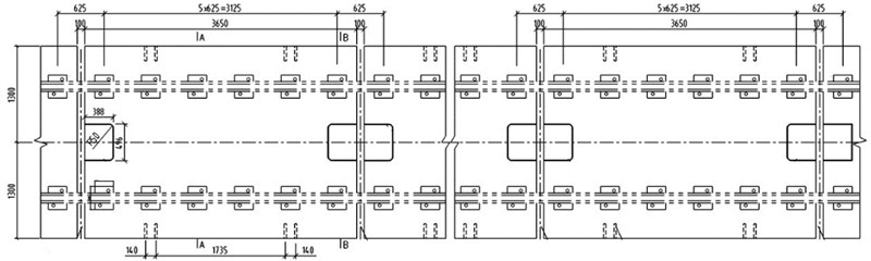
The damping pads were designed as floating slabs in a single-track configuration, with the slab length determined by the track layout and typically set at 3.65 m. The slab width was standardized to 2600 mm, while the bottom thickness measured 310 mm and featured a 2.5 % cross slope at the top. The sleepers utilized had dimensions of 170 mm × 250 mm × 310 mm. Fig. 1 illustrates the cross-sectional diagram of the damping pad floating slab.
Fig. 1Single-line damping pad floating slab plan (Unit: mm)
2.2. Modal analysis
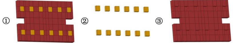
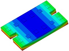
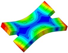
Conduct a modal analysis of the single-line vibration isolation foundation using a finite element model, as depicted in Fig. 2. In the figure, (1) denotes the finite element model of the floating slab, comprising two components: (2) represents the finite element model of the sleeper, and (3) signifies the finite element model of the concrete subgrade.
Fig. 2Single-line vibration damping pad floating slab finite element model
The single-line damping pad floating slab underwent modal analysis, and the findings are presented in Table 1. It is evident from the table that an increase in the stiffness of the damping pad corresponds to a rise in the first 6 modal frequencies of the floating slab structure. Fig. 3 illustrates the modal diagram of the damping pad isolation foundation for the initial 6 modes.
Table 1Natural frequencies of floating slab structures with different damping pads’ stiffness
Order | Resonant frequency | |||
0.01 N/mm3 | 0.02 N/mm3 | 0.03 N/mm3 | 0.04 N/mm3 | |
1 | 9.89 | 13.97 | 17.08 | 19.69 |
2 | 18.26 | 25.83 | 31.63 | 36.51 |
3 | 67.44 | 67.50 | 67.56 | 67.63 |
4 | 87.98 | 88.15 | 88.32 | 88.49 |
5 | 139.25 | 139.35 | 139.46 | 139.57 |
6 | 145.91 | 145.91 | 145.91 | 145.91 |
Fig. 3First 6 modal responses of the vibration isolation pads on the floating slab
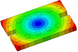
a) Order 1
b) Order 2
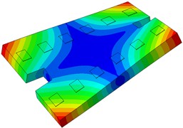
c) Order 3
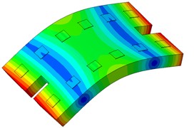
d) Order 4
e) Order 5
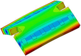
f) Order 6
It is noteworthy that due to railway authority constraints on spatial limitations, positions for points 5 and 6 are restricted to a distance of precisely 12 m from the column center. This layout meticulously considers space utilization and measurement accuracy factors. Points 13 and 15 are situated on the floor center for precise vibration measurements while Point 14 is strategically placed within the beam structure for accurate vibration analysis.
Furthermore, the remaining points are strategically located adjacent to columns, enabling comprehensive measurement of vertical vibrations. This meticulous arrangement takes into account various considerations allowing instruments to comprehensively capture diverse vibration conditions thereby providing robust primary data essential for subsequent analytical processing.
3. Application
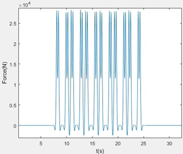
By applying vibration damping pads to the roof structure of a high-speed railway, the effectiveness was tested. In this case, the vehicle design speed is 25 km/h. The prediction model uses the track structure type without vibration damping measures (ballasted track bed) and the vibration damping pads. The rail type is 50 kg/m, the fastener stiffness is set to 60 MN/m, and the spacing between sleepers is 0.625 m. The reaction force of the fastener is input in Fig. 4.
Fig. 4Reaction force of the fastener
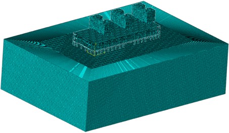
The modeling was conducted within a 152.5 m (longitudinal) by 62 m area, as illustrated in the subsequent Fig. 5.
Fig. 5Finite element model
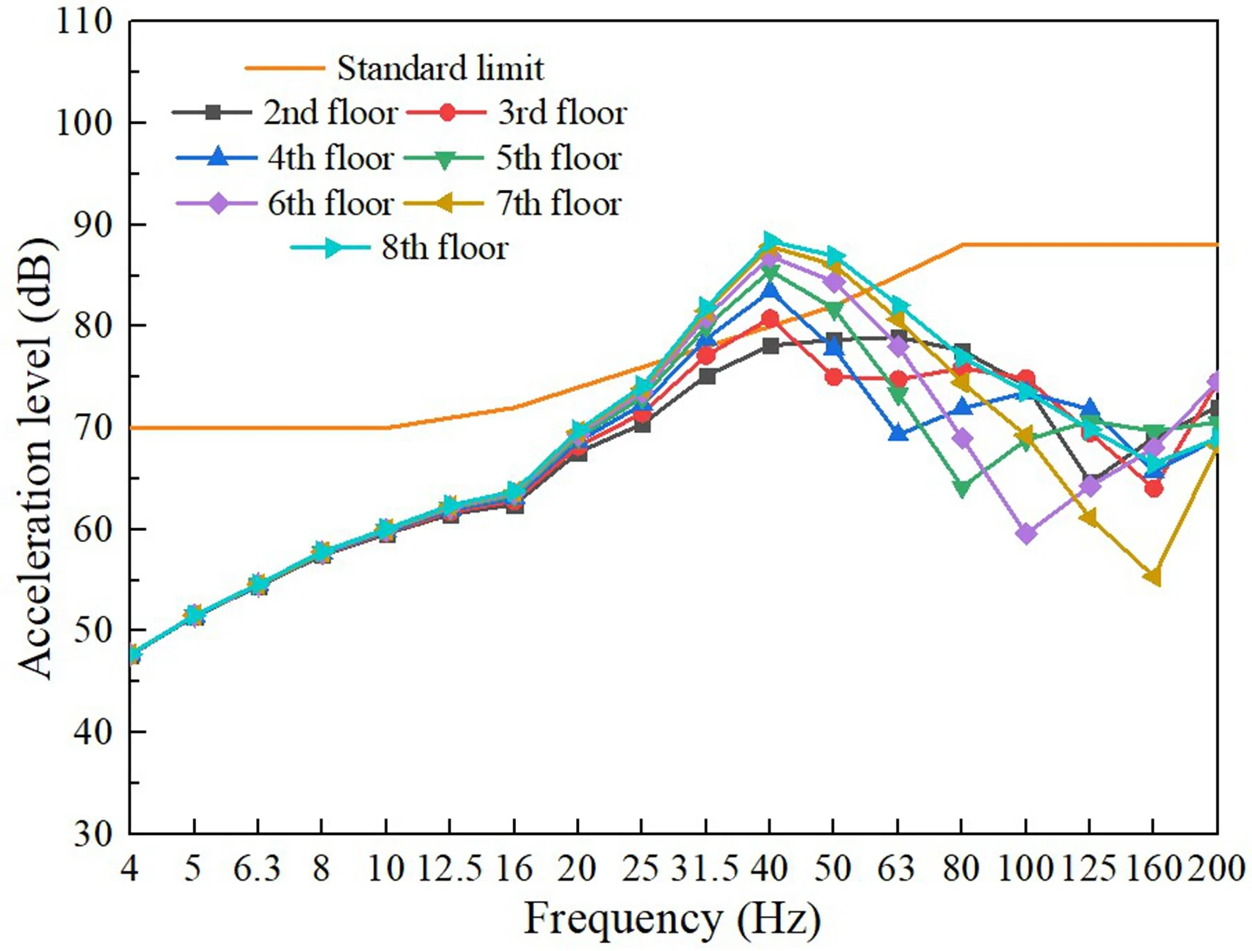
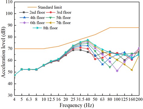
Upon considering the scenario where the train operates on the second level without any damping measures, Fig. 6 illustrates the anticipated vibration outcomes resulting from the train’s operation. In accordance with the 1/3 octave band (GB/T50355-2018), all levels exceed the thresholds at 50 Hz and 63 Hz.
Fig. 6Building vibrations caused by train movements (without damping measures)
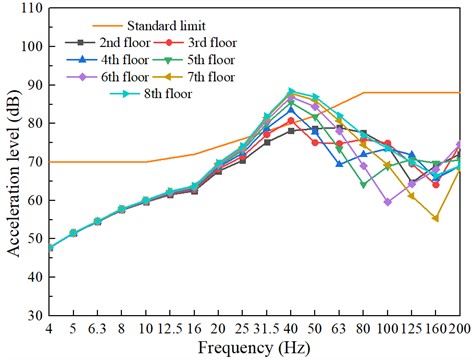
Fig. 6 vividly illustrates the vibration responses of sensitive points on each floor following the implementation of vibration isolation pads. The graphical representation demonstrates a significant reduction in vibration levels, showcasing the effectiveness of the isolation pads in mitigating vibrations.
Upon examination, it becomes evident that the use of vibration isolation pads has successfully curtailed the propagation of vibrations from the source to various floors, thereby ensuring a more comfortable and less disruptive environment for inhabitants. This is corroborated by the plummeting vibration responses observed across all sensitive points, validating the robustness of the isolation pads in providing a stable and vibration-free environment.
In conclusion, the implementation of vibration isolation pads has proven to be a pragmatic solution in controlling vibrations and enhancing the quality of life for those living in multi-story buildings.
Fig. 7Building vibrations caused by train movements (with damping measures)
4. Conclusions
This study employs various vertical stiffness damping pads to construct a floating slab with integrated damping system. By optimizing the stiffness and arrangement of the isolators, the modal properties of the floating slab are analyzed, resulting in a reduction of the natural frequency of the track structure and mitigating vibration transmission. Subsequently, this damping system is implemented in an actual engineering project, and its efficacy is evaluated.
1) The lower the stiffness of the vibration isolation pad, the smaller the natural frequency of the vibration isolation pad floating slab, thereby enhancing its effectiveness in mitigating vibrations.
2) Vibration isolation pads, supported by elastomeric bearings, are employed within track structures to mitigate the impact of train-induced vibrations on superstructures.
References
-
M. Saitoh, “On the performance of lumped parameter models with gyro‐mass elements for the impedance function of a pile‐group supporting a single‐degree‐of‐freedom system,” Earthquake Engineering and Structural Dynamics, Vol. 41, No. 4, pp. 623–641, Apr. 2012, https://doi.org/10.1002/eqe.1147
-
J. Zhang, Q. Gao, S. J. Tan, and W. X. Zhong, “A precise integration method for solving coupled vehicle-track dynamics with nonlinear wheel-rail contact,” Journal of Sound and Vibration, Vol. 331, No. 21, pp. 4763–4773, Oct. 2012, https://doi.org/10.1016/j.jsv.2012.05.033
-
Z. Wu, T. Chen, T. Zhao, and L. Wang, “Dynamic response analysis of railway embankments under train loads in permafrost regions of the Qinghai-Tibet Plateau,” Soil Dynamics and Earthquake Engineering, Vol. 112, pp. 1–7, Sep. 2018, https://doi.org/10.1016/j.soildyn.2018.04.047
-
J. Y. Shih, D. J. Thompson, and A. Zervos, “The influence of soil nonlinear properties on the track/ground vibration induced by trains running on soft ground,” Transportation Geotechnics, Vol. 11, pp. 1–16, Jun. 2017, https://doi.org/10.1016/j.trgeo.2017.03.001
-
G. Lombaert and G. Degrande, “Ground-borne vibration due to static and dynamic axle loads of InterCity and high-speed trains,” Journal of Sound and Vibration, Vol. 319, No. 3-5, pp. 1036–1066, Jan. 2009, https://doi.org/10.1016/j.jsv.2008.07.003
-
Y. Cui, K. Kishida, and M. Kimura, “Prevention of the ground subsidence by using the foot reinforcement side pile during the shallow overburden tunnel excavation in unconsolidated ground,” Tunnelling and Underground Space Technology, Vol. 63, pp. 194–204, Mar. 2017, https://doi.org/10.1016/j.tust.2016.12.014
-
D. Connolly, A. Giannopoulos, and M. C. Forde, “Numerical modelling of ground borne vibrations from high speed rail lines on embankments,” Soil Dynamics and Earthquake Engineering, Vol. 46, pp. 13–19, Mar. 2013, https://doi.org/10.1016/j.soildyn.2012.12.003
-
W. He, K. He, C. Yao, P. Liu, and C. Zou, “Comparison of damping performance of an aluminum bridge via material damping, support damping and external damping methods,” Structures, Vol. 45, pp. 1139–1155, Nov. 2022, https://doi.org/10.1016/j.istruc.2022.09.089
About this article

The authors have not disclosed any funding.
The datasets generated during and/or analyzed during the current study are available from the corresponding author on reasonable request.
The authors declare that they have no conflict of interest.
