Abstract
The aim of this work is the analysis of passive and semi-active damping methods on the model woven beam with a piezoelectric (PZ) layer. The mathematical model of the PZ layer on cantilever beam is derived. For modeling, real product parameters of PZ layer are used, and through simulation find the optimal values to dampen it. The resistive-inductance passive model, and State-Switch Damping SSD semi-active model are used in this work. The models are processed in the MATLAB Simulink environment and the results of the behavior of the models compared to each other. The program involving passive and semi-active systems, where analyze the behavior of the model for different parameters and the damping capabilities of individual methods are compared. The simulation results show the effectiveness of the semi-active system in comparison with the passive systems, also it shows the passive method is not so effective at low frequency as it in high frequency, and the semi-active method is not optimal for high frequency vibration.
1. Introduction
The development of electronics, increasing demand and increased demands on physical properties crystals contributed to the development of hydrothermal synthesis. This newly improved process allowed the growth of synthetic crystals on an industrial scale, especially synthetic quartz, and greatly accelerated the research of new compounds [1]. The first use of piezoelectric material to dampen mechanical vibrations with the electrical circuit was in (1979) which succeeded dampening the vibrations of the individual mirrors of the optical system by placing the elements in the frame construction. Furthermore, piezoelectric ceramics and the possibility of damping with shunt is dealt with by the group of Uchino et al. in the period of the 80s and 90s. By transforming kinetic energy into electrical energy, subsequently wasted into Joule heat by means of a resistor shunt, it was possible to dampen the mechanical vibrations of the damped structure, and by changing the resistance it was possible to change the damping of the system. The group of Uchino et al. also considered the possibility of using these vibrations to generate electrical energy and presented wearable energy harvesting prototypes [2].
Piezoelectric elements can be used as damping devices as well as sensors due to direct energy conversion. Piezoelectric elements are widely used for active damping of smaller devices, where they excel in quick system response, but also in aviation, where their main advantage is size and weight. Several strategies can be used to dampen the system, which purposefully reduce the amount of incoming energy, and the energy stored by the system. By moving the natural/resonant frequency outside the excited frequency, the amount of energy required to induce oscillations with the same amplitude as in the vicinity of the resonance can be increased [3]. The natural frequency of the system can be influenced by changing the mass or stiffness of the system, this option is not always offered, then it is necessary to improve the dissipation capacity of the system.
Passive systems do not dispose of external energy, they react to changes in the system and dissipate the energy transferred to them from the structure. The efficiency of this transmission varies with the setting of the passive damper, which is most often tuned around the natural frequency. These solutions are robust in their working range, but their effectiveness decreases when system parameters and working conditions change. To extend the working frequency by passive damping, an array of dampers tuned to several specific frequencies can be applied.
Semi-active systems are energy-independent or undemanding, but compared to passive methods, they can change their parameters such as stiffness k or damping d and thus respond to changing operating conditions, expand the working area or shift the natural frequency of the system. They are a compromise between passive and active damping.
One of the first semi-active approaches is SSD (State-Switch Damping), here methodical load switching is used. William W. Clark tested the SSD method, which switches between short/open and resistive/open every 1/4 cycle. A load with a small resistance value (short circuit) is closed when the structure returns to equilibrium position and disengaged when moving out of equilibrium position. In the work of Clark, it was found that an optimally tuned resistive load has better damping properties than an SSD circuit, but the latter achieves better properties outside of resonance and when the system tuning/properties change [4]. The SSD method is ideal for systems where rigidity is critical. It greatly affects the overall stiffness of the system [5].
Another method based on the previous solution is SSDI (Pulse State-Switch Damping on Inductor), this method uses switched series RL loads correctly phased with the mechanical part of the system. The load is connected at the maximum deflection of the system and disconnected as soon as the charge in the load reaches the maximum [5]. This method is influenced by the quality factor Q=E stored in load / E lost per cycle of the electrical elements of the load (switch, coil, line).
In this work, a simulation comparison between passive and semi-active vibration damper for cantilever beam is presented. The main new idea of the work is to improve the effectiveness of the semi-active system through simulation in comparison to passive system. In the later sections the vibration damping using passive, active, and semi-active procedure will be illustrated. The mathematical model of vibration, passive damper and semi-active damper is also shown. Simulation for the models is then addressed to show the comparison between the passive and the semiactive approach.
2. Dynamic system model with piezoelectric element
Analytical models are able to describe relatively simple homogeneous systems, such as the models of the embedded beam (Euler Beam Theory) or thin plates (Kirchhoff-Love Plate Theory) with considerable accuracy. By using a model described by a compact system of mathematical equations, the ability to repeat the analysis of a system with different parameters, where the influence of parameter changes on the behavior of the system can be observed and a general theory can be formulated. This type of equations also enables fast (real-time) calculation of the current state of the system, which is necessary for active control of the system.
The discrete approach defines the system using discrete equations, which are written in matrices for clarity. This type of model is applicable to more diverse shapes when the structure is converted to a finite element mesh. These models are used in the design of real systems and their modal analysis, when it is possible to make predictions and visualize the vibration modes of a structure that would otherwise be very difficult to describe analytically. The finite element method is also used to obtain global coefficients during system reduction.
When modeling the piezoelectric system under study, a linear beam model of the piezoelectric VEH (Vibration Energy Harvesting) based on the Mide V21BL VEH is used. This piezoelectric layer oscillator model is reduced to 1 DOF (Degree of Freedom) (Fig. 1). The vibration model here is reduced to 1 DOF due to the fact that the most important mode of vibration is the first mode which has the high amplitude, the higher modes of vibration can be neglected. The limitation of the model is that the model cannot handle the higher neglected modes. The differential equation of motion with the piezoelectric layer describing this system can be written:
individual quantities and their values [6]: z – position of mass point (m), m – reduced mass (Kg), k – reduced stiffness (N/m), d – mechanical damping (Ns/m), y'' – excitation acceleration (m/s2), v – voltage of the piezoelectric device terminals (V), C – capacitance of the piezoelectric layer (F), Θ – coupling coefficient (N/V), Z – load impedance (Ω).
Fig. 1Piezoelectric reduced single-degree-of-freedom system [6]
![Piezoelectric reduced single-degree-of-freedom system [6]](https://static-01.extrica.com/articles/24534/24534-img1.jpg)
3. Passive approach
Passive procedure were the first PEM (Piezo_Electrical_Mechanical) systems investigated, consisting of a combination of resistor, coil and capacitor in both series and parallel connections. Their operation is compared to elasto-viscous dampers for purely resistive loads, or TMD dampers for a resonant RL circuit (Hagood and von Flotow [7]), when must not neglect the capacitance Cp of the piezoelectric element itself in parallel with the R or RL load. Purely resistive solutions are simple to implement, but generally do not have a strong damping effect. The efficiency of these solutions decreases outside the working tuning frequency, parallel and branch connections between multiple PEM elements are built to cover a larger number of working frequencies. The disadvantage of damping using an RL load circuit is the increasing size of the inductance of the coil, which reaches high L values (> 1 H) at a low natural frequency (< 200 Hz), such large inductance values can be solved with synthetic circuits, but they must be powered.
In this work the maximum possible excitation is determined according to the VEH Mide V21BL catalog sheet describing the maximum deviation from the equilibrium position for the given product. The excitation is identical for all simulated systems in order to obtain a reference for measuring the damping methods used. After the system has stabilized, the amplitude can be determined, at a given excitation frequency of the system, at which the system has stabilized. The resistive load R is optimized in this work by iterations of load values and excitation frequency. The optimization process led to the R value for which the maximum excitation amplitude is the lowest and at which R value the strongest damping of the system occurs.
4. Semi-active approach
Semi-active refers to a damping circuit combining elements of active and passive connection. According to the speed of adaptation of the connection to the working conditions, adaptive-passive solutions can be distinguished, which are tied to the sensing of slower phenomena, such as changes in the temperature of the surrounding environment, compared to semi-active ones [8], which work similarly to active solution, in a cycle of vibrations. Compared to active ones, they try to use their own vibration energy to dampen the system and reduce the energy requirements of the control by using e.g. PM as a sensor or control without the need for complex control circuits.
The term semi-active load when it is necessary to implement a passive circuit element with unrealistic parameters using spare circuits is represented by operational amplifiers. Operational amplifiers are active elements that can be operated in both linear and non-linear modes of operation. By appropriately setting the parameters of the replacement circuit, to get the ability to achieve zeroing of the imaginary component of the complex impedance of the piezoelectric element at a specific frequency and achieve optimal damping. This situation corresponds to a short circuit of the inverter output terminals. By series combination of NC and resistor with resistance R of appropriate size, maximum damping can be achieved.
5. Simulations
In this section, the system of differential equations mentioned Section 2 rewritten into a diagram composed of functional blocks of the Simulink program. The behavior of the system over time can be simulated using a sufficiently small (1×10⁻⁵ s) discrete time step of the simulation, when vibrate the system from a rest position (zero initial conditions) by a constant sinusoidal signal representing the ¨y acceleration of the system, which can be expressed as the product of mass and applied force. The maximum possible excitation is determined according to the VEH Mide V21BL catalog sheet describing the maximum deviation from the equilibrium position for the given product. The excitation is identical for all simulated systems to obtain a reference for measuring the damping methods used. After the system has stabilized, the amplitude can be determined, at a given excitation frequency of the system, at which the system has stabilized.
5.1. Damping simulation using passive approach
By plotting the dependence between the values R of the load, f exciting and from stabilization, a saddle-shaped surface is created (Fig. 2), the minimum of the primary frequency can be observed on the surface. R optimum for the simulated system corresponds to a value of 262 kΩ.
Together with the optimization of the R value, the behavior of the system in short circuit (short circuit) and open circuit (open circuit) can be considered as limit states. A short circuit will cause an instantaneous discharge of the capacitance of the piezoelectric layer, so that in Eq. (1), the third term of the right-hand side, θ v/m, of the mathematical model will be zero. Without the influence of this term, the equation behaves the same as a purely mechanical system. Using constant excitation, the effect of the damping of the mechanical part and test the response of the system can be eliminated, which for a short circuit should correspond to the natural frequency of the reduced system according to relation.
To achieve optimal damping with RL, it is necessary to match the mechanical part of the system with the electrical one by setting the optimal inductance value L, depending on the own capacitance of the piezo material C and the frequency of the mechanical system as shown in Fig. 3. At resonance, the values of inductive and capacitive reactance XL≈XC are equalized in the electric circuit. The optimal values of the series-connected RL members for the given system are: L= 1198 H and R= 56 kΩ. For the low frequency and the given capacity of the system under study, it gave a very high inductance value of the necessary coil, which is not feasible with a traditional component. The capacitance of the piezoelectric layer can also be reduced by using a synthetic negative capacitance connection. A value close to the optimal inductance value can be found by using Thomson’s relation and subsequent fine-tuning. In this case, the resistor affects the selectivity of the circuit, for higher values of R observe a higher quality value of Q and a narrower band. The optimal R can again be identified by iterations of the values.
5.2. Simulation of semi-active approach
The simulation of the SSD technique is done according to [5], where switch the system according to the state in which it is located. Specifically, when the system moves from the equilibrium position, the load will be uncoupled, so the system will be stiff against the change in Position, and the voltage on the piezo element will increase with the deflection. When the maximum amplitude is reached, close, quickly wasting the energy accumulated by the piezoelectric element, reducing the effective stiffness of the system, so that the available potential energy of the return oscillation drops from the maximum position Fig. 4.
Fig. 2Amplitudes vs R vs excitation frequency
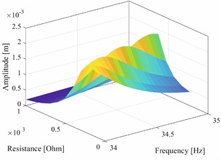
Fig. 3Amplitudes vs R vs excitation frequency
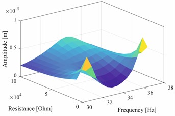
Fig. 4Amplitudes vs R vs excitation frequency
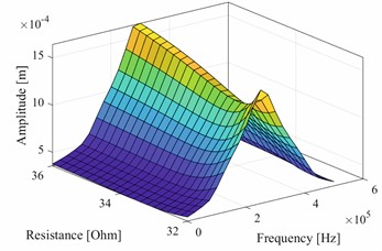
Fig. 5Switching logic for SSD technique vs time of quantities: speed, position, state, voltage
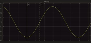
a) Velocity
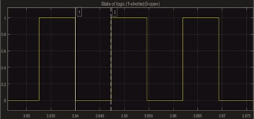
b) State of logic
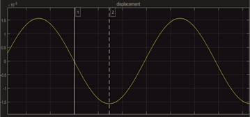
c) Displacement
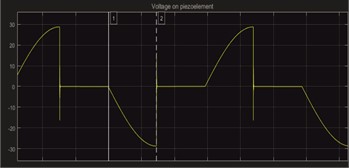
d) Voltage
Similar to the case of a resistive load, a saddle-shaped shape (Fig. 5) of the amplitude depending on the switched value of the resistive load is observed. The optimal value of the switching load R optimal = 105 kΩ was found. It is clear that the effectiveness of this technique depends significantly on the synchronization of the load switch and the waveform mechanical oscillations, and thus also the course of the electrical voltage at the output piezoelectric element.
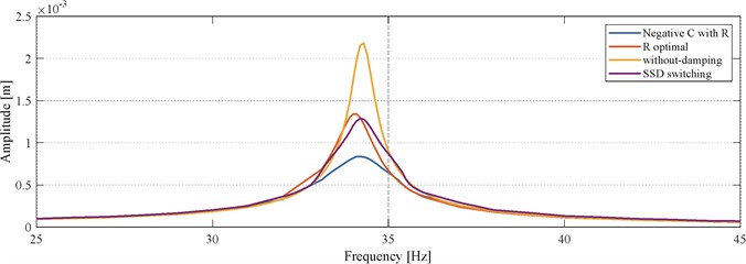
Compared simulations were performed with constant harmonic excitation for each frequency investigated. In the vicinity of the resonance frequency of the mechanical system, a finer division on the frequency axis was chosen. The results of the simulations were a clear comparison inserted into one graph as shown in Fig. 6.
Fig. 6Comparison of frequency characteristics of individual damping methods
6. Conclusions
The analysis of the damping capabilities of individual damping methods was performed on a theoretical model based on Midé V21BL parameters. The modeling was based on a reduced analytical model describing the dynamics of a woven beam with a piezoelectric layer. Models based on easy-to-implement principles of passive damping, as well as a linear model of semi-active damping using synthetic negative capacitance, and a non-linear model of resistive load switching were compiled. The results obtained by comparing passive and semi-active damping methods were in accordance with the results published in the studied literature. The method of semi-active damping with synthesized negative capacitance was evaluated as effective and usable. In order to verify the obtained results and further investigate this load in combination with synchronous switching, a design of a test fixture was made, which is ready for implementation and evaluation.
References
-
K. Byrappa and M. Yoshimura, Handbook of Hydrothermal Technology. India: Elsevier, 2013, https://doi.org/10.1016/c2009-0-20354-0
-
K. Uchino, Advanced Piezoelectric Materials. USA: Woodhead Publishing, 2017.
-
I. P. Lyan, G. Y. Panovko, and A. E. Shokhin, “On the issue of energy consumption of vibration technological machines,” in IOP Conference Series: Materials Science and Engineering, Vol. 747, No. 1, p. 012055, Jan. 2020, https://doi.org/10.1088/1757-899x/747/1/012055
-
A. Mohammadi, M. R. Zakerzadeh, A. Yousefi-Koma, S. Mohajerin, and S. Zohoori, “Passive vibration control of a cantilever beam using shunted piezoelectric element,” in 5th RSI International Conference on Robotics and Mechatronics (ICRoM), Vol. 146, pp. 389–393, Oct. 2017, https://doi.org/10.1109/icrom.2017.8466191
-
H. Ji, J. Qiu, L. Cheng, and H. Nie, “Semi-active vibration control based on unsymmetrical synchronized switch damping: Analysis and experimental validation of control performance,” Journal of Sound and Vibration, Vol. 370, pp. 1–22, May 2016, https://doi.org/10.1016/j.jsv.2016.01.033
-
O. Rubes, M. Brablc, and Z. Hadas, “Verified nonlinear model of piezoelectric energy harvester,” in MATEC Web of Conferences, Vol. 211, p. 05005, Oct. 2018, https://doi.org/10.1051/matecconf/201821105005
-
N. W. Hagood and A. Von Flotow, “Damping of structural vibrations with piezoelectric materials and passive electrical networks,” Journal of Sound and Vibration, Vol. 146, No. 2, pp. 243–268, Apr. 1991, https://doi.org/10.1016/0022-460x(91)90762-9
-
J. Cheng, H. Ji, J. Qiu, and T. Takagi, “Semi-active vibration suppression by a novel synchronized switch circuit with negative capacitance,” International Journal of Applied Electromagnetics and Mechanics, Vol. 37, No. 4, pp. 291–308, Nov. 2011, https://doi.org/10.3233/jae-2011-1402
About this article

The authors have not disclosed any funding.
The datasets generated during and/or analyzed during the current study are available from the corresponding author on reasonable request.
The authors declare that they have no conflict of interest.
