Abstract
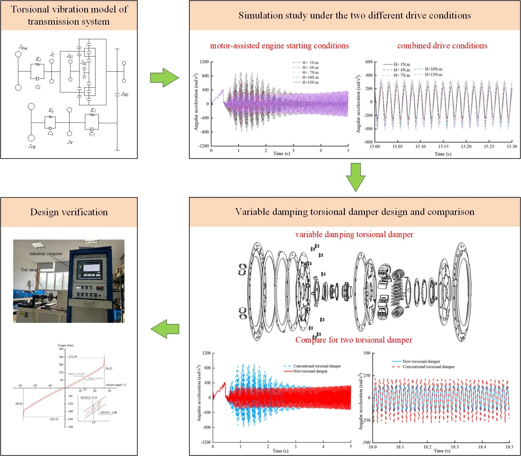
The torsional vibration of hybrid electric vehicles (HEVs) powertrain coupled with multiple power sources is more complex, and the hysteresis torque requirements are different under different working conditions. Therefore, this study investigates the impact of the hysteresis torque value on damping performance for torsional dampers under diverse working conditions through modeling and simulation. A configuration for a torsional damper that enables variable hysteresis torque in different working conditions is proposed. Simulation results demonstrate that the variable hysteresis torsional damper reduces angular acceleration fluctuation amplitude by 54.5% during motor-assisted engine starting and by 20.2 % during combined drive conditions compared to traditional dampers, effectively attenuating vibration under two different working conditions. The proposed variable hysteresis torsional damper configuration is verified to meet design requirements for different working conditions.
Highlights
- A novel torsional damper with variable hysteresis torque is designed.
- To investigate the effect of hysteresis torque values on the damping performance of torsional vibration dampers under different operating conditions.
- The variable hysteresis torsional damper reduces angular acceleration fluctuation amplitude by 54.5% during motor-assisted engine starting and by 20.2% during combined drive conditions compared to traditional dampers.
1. Introduction
With the rapid development of the automobile industry, the state has introduced strict energy conservation and emission reduction policies, prompting automobile manufacturers to gradually develop hybrid vehicle technology. Hybrid electric vehicles (HEVs) face the coupling and decoupling of multiple power sources because of its two power sources of engine and motor, which brings more complex noise and vibration to the transmission system [1-3], and brings new challenges to the noise, vibration, harshness (NVH) performance of the HEVs.
HEVs are able to perform dynamic mode switching according to real-time demand power to achieve both power and fuel economy. However, frequent mode switching also easily induces torsional vibration in powertrain [4],[5]. Regarding the torsional vibration problem of HEVs, Tang et al. [6] analyzed the key factors to affect the torsional vibration of the powertrain under engine and electric motor excitation based on a planetary gear hybrid vehicle. Zhang et al. [7] designed an active vibration reduction controller for the torsional vibration problem of planetary gear HEV. The torsional vibration of the powertrain is suppressed by the output compensation torque of the two motors. Zhang et al. [8] optimised the control strategy of a HEV by establishing a nonlinear dynamics model for the powertrain to reduce the vibration noise of the vehicle. The above mentioned scholars have researched on suppression of torsional vibration in hybrid vehicles by designing appropriate control strategies and controllers, whereas, another widely used method is to install a torsional damper [9].
There are mainly two types torsional dampers equipped in HEVs: dual-mass flywheel [10] and clutch torsional damper [11]. The torsional damper is widely used in HEVs because of its advantages of low cost and mature technology. In order to study the working mechanisms of the torsional damper, scholars have conducted a large number of studies on its structural parameters and torsional characteristics. Yan et al. [12] proposed a torsional damper for HEV, and its damping effect was verified by simulation and experiment, which provided a reference scheme for the torsional damping of the HEV powertrain. Yan et al. [13] analyzed the structure and characteristics of the torsional damper and performed a sensitivity analysis of the torsional damper parameters. Schaeffler [14] also proposed a new torsional damper configuration to reduce the powertrain resonance by optimizing the hysteresis torque value. Wang et al. [15] optimized the resonance speed by adjusting the stiffness of the torsional damper to move the engine away from its resonance speed range. Although the above literature has conducted extensive research on torsional dampers, few scholars have studied the torsional vibration problem of HEV under multiple operating conditions and researched a variable hysteresis torsional damper to solve multi-condition torsional vibration.
HEVs have multiple driving modes, and the torsional vibration of the powertrain exhibits different characteristics under different driving modes. The torsional vibration generated by the engine ignition in HEVs under motor-assisted engine starting conditions has a significant impact on the powertrain [16]; In additional, the powertrain in combined drive conditions has coupled vibration from different two excitation sources for engine and motor [17], [18]. Literature [19], [20] investigated the torsional vibration of a powertrain system during engine starting conditions and developed a multi-stage torsional damper to reduce the torsional vibration of the powertrain. Literature [21] designed a torsional damper to reduce the torsional vibration of the powertrain under combined drive conditions. The design of the torsional damper for the HEV under motor-assisted engine starting and combined drive conditions is only analyzed separately, and scholars do not consider the characteristics of the two conditions at the same time to design a torsional damper that meets the hysteresis torque requirements of the two conditions.
According to the above analysis, in this paper, for the torsional vibration phenomenon of the HEV under motor-assisted engine starting and combined drive conditions, a new variable hysteresis torsional damper is designed based on a certain planetary gear HEV powertrain to meet the different hysteresis torque requirements of the torsional damper under the two working conditions. First, the dynamic analysis of planetary gear HEV is carried out under the conditions of the engine participation. Second, the dynamic simulation model of powertrain is established, and the hysteresis torque requirements of the torsional damper under two conditions are studied. Then, based on the simulation results, a new type of variable hysteresis torsional damper is designed, which can satisfy the different hysteresis torque requirements under two working conditions. Finally, the performance of the new type of torsional damper is verified by the experiment.
2. Modeling of planetary gear hybrid systems
2.1. Transmission scheme and torsional vibration modeling equations
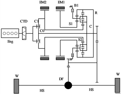
A planetary gear HEV studied in this paper is shown in Fig. 1. It is driven by the engine and two motors that can be used as generators. The three power sources are coupled together through the planetary gear mechanism to realize the power split of the engine. The engine (Eng) transmits its power to the planetary gear mechanism via the clutch torsional damper (CTD), with the sun gear and the planetary carrier serving as the power input shafts. The motors EM1 and EM2 are connected to the small sun gear (S1) and the large sun gear (S2), respectively. The ring gear (R) is composed of an inner and outer ring gear. The inner ring gear is meshed with the planetary gears, and the outer ring gear is connected to the reduction gear (FR) as the output mechanism, which ultimately drives the front wheels (W) through the FR, the differential (DF), and the left and right half shafts (HS). Additionally, the hybrid system includes two clutches (C0, C1) and a brake (B1), which allow the system to switch between various modes, achieving higher fuel efficiency and lower emissions.
Fig. 1New planetary gear hybrid system structure
To analyze the working principles of the planetary gear hybrid power system, the lever simulation analysis method can be employed [22]. The equivalent lever principle of the system is illustrated in Fig. 2. This principle consists of four vertical axes and one horizontal axis, with the intersection points of the lever and axes representing the velocity of each component. The direction of the arrows on each axis indicates the torque output direction for each component. Based on this, the rotational speed relationships within the power-splitting mechanism can be established.
Fig. 2System equivalent leverage diagram
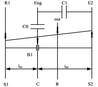
The rotational speed of the composite planetary gear set is governed by two gear ratios, and the relationship can be expressed as follows:
where ns1, ns2, nc and nout are the rotational speeds of S1, S2, the planetary carrier, and the output shaft, respectively; i01 is the ratio of the front planetary gear and i02 is the ratio of the rear planetary gear.
The dynamics of the planetary gear set, in steady-state operation, can be expressed as:
where Tout is the output torque of the gear ring, Ts1 and Ts2 are the output torque of the S1 and S2, respectively, and Tc is the output torque of the planetary carrier.
The power relationship between the axis is expressed as:
The torque between individual shafts can be described by the following equations:
where TE1, TE2, TEng are the output torque of the motor EM1, EM2, and engine, respectively, TLoad is the resisting torque from the vehicle, and JE1, Js1, JEng, Jc, Jout, JE2, Js2 represent the moments of inertia for their respective components.
The vibration of planetary gear HEV is caused by the complex dynamic response under the coupling action of multiple excitation sources and multiple transmission paths. To accurately predict torsional vibrations in the powertrain and investigate the relationship between the torsional damper and torsional vibration, this study employs a simplified general method for analyzing torsional vibrations. The model includes key components such as the engine, torsional damper, motor, planetary gear, reducer, differential, half shafts, wheels and body. The certain simplifications are made:
(1) The moment of inertia of elements with large and concentrated inertia is considered at the center of rotation, treated as rigid bodies without elasticity. Components with small and dispersed inertia are modeled as springs with elasticity but no inertia.
(2) Auxiliary components like the oil pump, hydraulic system, and cooling mechanisms are omitted.
(3) Manufacturing errors, installation errors, and wear deformations of shafts and gears are neglected.
(4) Gear clearances and frictional resistance are not considered.
(5) Vibrations in directions other than torsional are neglected.
In the modeling process, the primary focus is on the stiffness and hysteresis characteristics of the torsional damper, which is simplified to a 2-degree-of-freedom (DOF) system. The simplified model is shown in Fig. 3.
Fig. 3Simplified model of torsional vibration of the torsional damper
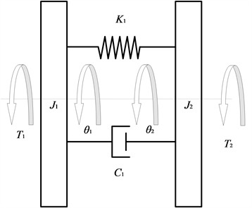
In Fig. 3, J1 is the moment of inertia for the torsional damper active part, J2 is the moment of inertia for the torsional damper driven part, θ1 and θ2 represent the torsional angular displacements for the torsional damper active part and driven part, respectively, T1 is the torque transmitted from the engine flywheel to the torsional damper active part, T2 is the torque transmitted through the torsional damper to the planetary carrier, K1 and C1 represent the torsional stiffness and damping of the torsional damper, respectively.
The torsional damper dynamics equations are obtained as follows:
Considering the working conditions of the HEV torsional damper, simulations are conducted under two working conditions: motor-assisted engine starting and combined drive modes. In both conditions, power is delivered to the wheels through various powertrain components, including flywheels, the torsional damper, continuously variable transmission (E-CVT), planetary gear, main reduction, and half shafts. The powertrain is transformed into a 7-dof simplified model consisting of moment of inertia, spring and damping, as shown in Fig. 4.
Fig. 4Torsional vibration model of transmission system
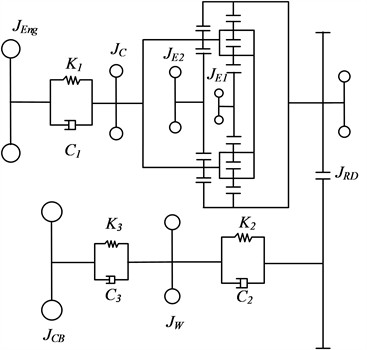
In Fig. 4, JEng is the rotational inertia of the engine and torsional damper active part, JC is the rotational inertia of the torsional damper driven part and planetary carrier, JE1 is the equivalent rotational inertia of the small motor and the small sun wheel, JE2 is the equivalent rotational inertia of the large motor and the large sun wheel, JRD is the equivalent rotational inertia of the gear rims, the main gearbox and the differential, JW is the equivalent rotational inertia of the wheel, JCB is the equivalent rotational inertia of the body, K2 and K3 are the torsional stiffnesses of the half shafts and tires, and C2 and C3 are the equivalent damping of the half shafts and tires.
For the E-CVT which is a two degree of freedom mechanism, according to the kinematic constraint relationship of the E-CVT, the generalized coordinates of the drivetrain can be expressed as:
where θ3, θ4, θ5 represent the angular displacements of the gear rim, tire, and body.
The Lagrange function of the system can be expressed as a function of generalized coordinates:
where VDS and UDS are the kinetic and potential energies of the drive train.
Without considering the external effects, the dynamic model of the transmission system can be obtained according to the Lagrange equation:
Bringing Eq. (12) into Eq. (15) yields a system of chi-square differential equations which can be expressed in terms of a matrix as:
where JDS, CDS, and KDS represent the mass matrix, damping matrix, and stiffness matrix of the electromechanical coupled system.
Included among these:
2.2. Torsional characteristics of torsional damper
When the engine is engaged in the planetary gear HEV’s operation, the alternating torque from the engine is the main source for torsional vibration of the powertrain. To study the torsional characteristics of the powertrain, this section focuses on the simulation study under the motor-assisted engine starting and combined drive conditions. The HEV analyzed in this paper is equipped with an E-CVT dedicated hybrid transmission, and the key parameters are presented in Table 1.
Table 1E-CVT key parameters
Item | Numerical value |
Overall mass (Kg) | 3075 |
Rolling resistance coefficient | 0.012 |
Frontal area (m2) | 6.3844 |
Maximum engine torque (Nm) | 350 |
Maximum engine power (kW) | 93 |
Maximum motor torque (Nm) | 250 |
Maximum motor power (kW) | 75 |
Front planetary gear static ratio | 3.133 |
Rear planetary gear static ratio | 2.26 |
Main reduction ratio | 3.98 |
For the planetary gear HEV, the engine is started by the motor, and the vehicle is driven by the motor during the driving process. When the engine is needed to work, the engine is started by adjusting the speed of the planet carrier with two motors. In this process, the starting of the engine will bring large torsional vibration to the powertrain, and finally reflected in the rotating parts of the speed fluctuation, so it is necessary to install a torsional damper to attenuate the torsional vibration of the powertrain. The simulation results of damping performance under motor starting condition with traditional torsional damper are shown in Figs. 5 and Fig. 6 [23], [24].
Fig. 5Angular acceleration fluctuation under motor-assisted engine starting conditions
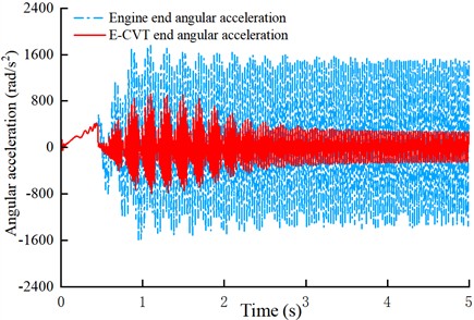
Fig. 6Angular speed under motor-assisted engine starting conditions
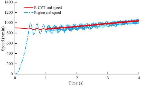
As shown in Fig. 6, under the motor-starting-engine conditions, the engine starts to be dragged when the rotational speed of the planetary frame is adjusted by the motor at 0.5 second, and the whole dragging process is completed about 1 second. By observing the torsional vibration at both ends of the torsional damper in Fig. 5, it can be seen that the angular acceleration of the E-CVT input has a large fluctuation in the motor-assisted engine starting conditions. From the engine ignition to idle stage, the speed fluctuation amplitude is about 200 r/min, and the angular acceleration fluctuation amplitude is about 1000 rad/s2. After the engine enters idle stage, the angular vibration of E-CVT tends to be stable, and the rotational speed fluctuation is about 38 r/min, and the amplitude of angular acceleration is about 431 rad/s2.
The selection of torsional damper parameters will have a significant impact on the damping performance, and different damping values have a significant impact on its performance [25]. The damping characteristics of the object necessitate a period of time for the transmission of force. Consequently, the torsional damper exhibits hysteresis during the torque transmission process. The damping characteristics exert a direct influence on the hysteresis characteristics, and the torque generated by the damping is referred to as the hysteresis torque. The hysteresis torque (H) of the torsional damper can be calculated by:
where ω is the angular velocity of the drive shaft and C is the damping.
In this paper, the H is used to represent the damping characteristics of the torsional damper. In order to solve the torsional vibration of the powertrain during engine starting, two working conditions of the engine were selected, and the fluctuation of the angular acceleration at both ends of the torsional damper was taken as the evaluation standard, to study the influence of the torsional damper damping characteristics on the damping performance.
In order to obtain the damping performance of torsional damper under different H, the sensitivity analysis of torsional dampers under two working conditions is carried out, the torsional vibration of two ends of torsional damper was analyzed by applying H of 1 Nm, 4 Nm, 7 Nm, 10 Nm, 13 Nm to the torsional damper.
Under motor-assisted engine starting conditions, torsional damper is compressed in the reverse direction, and the angular acceleration fluctuation of its driven disk end is shown in Fig. 7.
Fig. 7The influence of damping value change
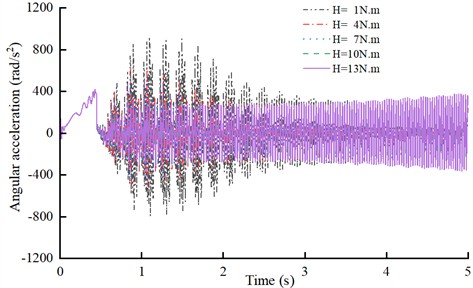
The torsional damper was negatively compressed during motor-assisted engine starting in reverse drag. The simulation results show that the peak to peak value of angular acceleration fluctuation at the input of the E-CVT decreases from 921.6 rad/s2 to 316 rad/s2, which is 34.2 % of the original value, when the H is increased from 1 Nm to 13 Nm during the starting process. The results demonstrated that the damping performance of the torsional damper when compressed negatively during engine starting was positively correlated with the hysteresis torque, and the larger the hysteresis torque is the significant damping effect is.
The E-CVT angular acceleration fluctuation is shown in Fig. 8, when the torsional damper is compressed in the forward direction under the combined drive conditions.
Under combined drive conditions, when the damper is compressed in the forward direction, simulation results indicate that increasing the damping value from 1 Nm to 13 Nm leads to an increase in angular acceleration fluctuation from 235 rad/s2 to 389 rad/s2 (a 65 % increase), worsening the torsional vibration. In this scenario, smaller damping values provide a better damping effect. Therefore, when the torsional damper is compressed in the forward direction, the damping effect is negatively correlated with the damping value.
Fig. 8Combined drive angular acceleration fluctuation
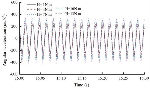
In the combined drive condition, when the torsional damper is compressed in the forward direction, the simulation results show that when the H of the torsional damper is increased from 1 Nm to 13 Nm, the amplitude of the angular acceleration fluctuation at the E-CVT end is increased from 235 rad/s2 to 389 rad/s2, and the amplitude of the angular acceleration fluctuation is increased by 65 %, which worsens the torsional vibration of the driveline. That is, when the torsional damper is compressed in the forward direction, the small damping effect is better. Therefore, when the torsional damper is compressed in the forward direction, the damping effect is negatively correlated with the damping value, and the smaller the damping value, the more significant the damping effect.
The H of the torsional damper under the above two working conditions are analyzed statistically, as shown in Table 2.
Table 2Comparison of the torsional vibration indices for the tow working conditions
Condition | H (Nm) | Peak to peak value (rad/s2) | Root mean square (rad/s2) |
Motor-assisted engine starting | 1 | 1711 | 316 |
4 | 1126 | 190 | |
7 | 1040 | 176 | |
10 | 639 | 157 | |
13 | 614 | 148 | |
Combined drive | 1 | 495 | 169 |
4 | 555 | 189 | |
7 | 622 | 211 | |
10 | 696 | 235 | |
13 | 767 | 259 |
According to the statistical results in Table 2, the torsional vibration of the driven disk is negatively compressed at the motor-assisted engine starting conditions, and the torsional vibration at the input end of the E-CVT decreases gradually as the H increases, the damping performance of the torsional damper is positively related to the H, and the angular acceleration fluctuation of the E-CVT input decreases with the increase of the H. The torsional vibration of E-CVT input increases with the increase of the H, while the torsional vibration of the driven disk is compressed forward, the damping performance of the torsional damper is negatively related to the H, and the angular acceleration fluctuation of the E-CVT input increases with the H.
Therefore, it is necessary to design a variable damping torsional damper for the different damping requirement under the start-up and combined drive conditions.
Structure and principle of variable damping torsional damper
Under motor-assisted engine starting conditions, the torsional damper is compressed to the negative direction, and a large amount of hysteresis is needed to attenuate the torsional vibration caused by the engine start. In the combined drive condition, the torsional damper is compressed in the positive direction, and small hysteresis can fulfill the working requirements. Therefore, a new torsional damper is designed in this section for these two working conditions, which can achieve variable hysteresis according to the torsional angle.
The structure of the new torsional damper is shown in Fig. 9. It is mainly composed of elastic elements and damping elements. The hysteresis mechanism of the torsional damper is set between two damping discs, radially placed on the inner side of the coil spring, so that the torsional damper works under different compression angles to provide different damping values. The springs used to provide the axial compression force in the torsional damper generally have two kinds of disc and the wave springs. In the working process of the torsional damper, the wave spring will reduce the axial compression force with the increase of the axial gap, and the hysteresis generated by the slipping grind will be reduced, which cannot meet the demand of vibration damping; Whereas the load deflection characteristic curve of the disc springs shows a nonlinear relationship, and the axial compression force will increase with the axial gap, so the torsional damper designed in this paper adopts an open-slotted type of disc springs, which can better meet the demand of vibration damping. The hysteresis mechanism of the torsional damper includes: damping plate 3, secondary disc spring 4, secondary damping plate 5, secondary damping spacer 6, primary disc spring 12, pre-damping damping plate 13, friction damping plate 14, and damping plate 15, which are axially inlaid in the flange portion of the damping disc 2, the wave plate damping disc subassembly 17, and the drive disc torque limiter 9.
Fig. 9Explosion diagram of variable damping torsional vibration damper: 1 – transmission side cover plate, 2 – damping disk, 3 – damping plate, 4 – secondary disc spring, 5 – secondary damping plate, 6 – secondary damping spacer, 7 – damping spring, 8 – spring holder, 9 – drive disk torque limiter, 10 – friction plate 1, 11 – disk hub, 12 – primary disc spring, 13 – pre-damping damping plate, 14 – friction damping plate, 15 – damping plate, 16 – balancing rivets, 17 – waveform plate damping disk sub-assembly, 18 – friction plate 2 , 19 – friction plate 3, 20 – diaphragm spring spacer, 21 – engine flywheel side cover plate, 22 – limit pin
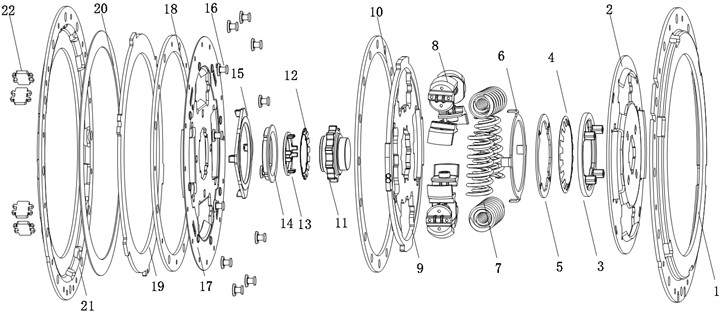
The damping of the torsional damper is achieved by dry friction of the damping pads between the two damping disks. The damping pads mounted between the two discs generate damping through the compression force transmitted by the disc springs to attenuate the resonance peaks of the driveline, thus optimizing the NVH performance of the vehicle during driving.
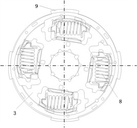
Fig. 10(a) shows the torsional damper in the no-load state, in which no torque is transmitted to the torsional damper and no relative rotation of the damping device occurs. When the planetary gear HEV under motor-assisted engine starting conditions, the damping spring of the torsional damper is compressed in the reverse direction. During this process, the input torque is transmitted to the damping device through the disk hub 11, causing the disk hub 11 to rotate counterclockwise with respect to the damping disk 2, as shown in Fig. 10(b). The disk hub 11 and the friction damping piece 14, the pre-damping damping piece 13 produce slip wear, the drive disk restrictor 9 and the damping piece 3, the damping piece 15 slip wear, so that the two pairs of damping pieces to produce a larger hysteresis, the drive disk restrictor 9 drives the second stage damping spacer 6 and the second stage damping piece 5, the damping piece 3 slip wear to produce a small hysteresis. When the damping spring is compressed to a certain angle with the drive plate limiting torque 9 and friction damping plate 14, pre-damping damping plate 13, damping plate 3, damping plate 15 together with the rotation, no longer occurs relative movement, resulting in the disappearance of the larger hysteresis, only the small hysteresis torque H1 play a role. When the damping spring is continued to be compressed, the secondary damping spacer 6 collides with the groove on the drive disk torque limiter 9, driving the drive disk torque limiter 9 and the friction damping piece 14, the pre-damping damping piece 13, the damping piece 3, and the damping piece 15 to rotate relative to each other again, and together they act to provide the large hysteresis torque H2 for the driveline.
In the motor-assisted engine starting conditions, the torsional vibration transmitted from the engine is large, and the damping spring of the torsional damper is compressed in the opposite direction to a larger angle to provide large hysteresis to meet the requirement of rapid attenuation of the peak resonance energy. In the combined drive conditions, the damping spring of the torsional damper is compressed in the positive direction, as shown in Fig. 10(c). Since the fluctuation from the engine is small in the combined drive conditions, the damping spring is compressed at a small angle, thus only the hysteresis torque H1 acts.
Fig. 10Function diagram of damping device
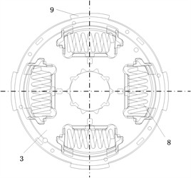
a) Unloaded
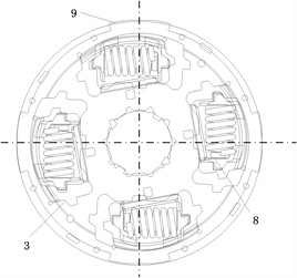
b) Backward compression
c) Forward compression
During the operation of the torsional damper, the friction between the friction elements generates damping, the value of which is twice the friction torque between the damped friction elements of the stage, and the damping is calculated by the formula:
where Th is the damping, R is the radius of the damping piece, a is the inner diameter of the friction damping piece, b is the outer diameter of the friction damping piece, P is the axial load, and μ1 is the friction coefficient of the friction damping piece.
Based on the definition of damping, it can be obtained that the main factors affecting damping are the load and area of the disc spring applying axial pressure and the coefficient of friction and force area of the friction damping plate.
At present, there is no accurate formula for disc springs, and an approximate calculation method (proposed by Alman and Laszlo, referred to as the A-L method) is generally used [27]. It is necessary to make two assumptions about it in advance:
1. The cross-section does not undergo twisting deformation.
2. The axial force and reaction force are uniformly distributed along the inner and outer circumference.
Then the relationship between axial load and deformation can be simplified as:
where E is the modulus of elasticity; D is the outer diameter of the disc spring; μ is Poisson’s ratio; h is the cone height of the disc spring; t is the thickness of the disc spring; f is the amount of deformation; the calculation coefficient K1 is calculated by the following formula:
where d is the inner diameter of the disc spring, C=D/d.
According to the formula analysis of the A-L method, h/t for the elastic properties of the disc spring is great, different h/t value has different elastic properties, generally choose √2<h/t<2√2 within the range.
Taking μ as 0.3, the range of values of H can be obtained by calculation as shown in Table 3.
From Table 3, it can be obtained that H1 obtained by calculation is 3.2 Nm and H2 is 9.0 Nm.
Table 3Hysteresis torque of torsional damper
Level | Friction pair | Working radius (mm) | H (Nm) |
First-order hysteresis | First friction pair | 20.43 | 3.2 |
Second friction pair | 35.02 | 5.8 | |
Second-order hysteresis | First + Second friction pair | 3.98 | 9 |
3. Results and discussion
3.1. Simulation results and discussion
The newly designed variable hysteresis torsional damper was installed in the drivetrain for testing, with the engine started using motor speed control. Under the motor-assisted engine starting conditions, the angular acceleration fluctuations at the output ends of the two torsional dampers were recorded, as shown in Fig. 11.
Fig. 11Angular velocity fluctuations under motor-assisted engine starting conditions
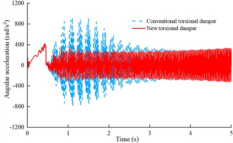
During motor-assisted engine starting conditions, the torsional damper provides a large hysteresis torque H2. The simulation results shown in Fig. 11 show that the angular acceleration fluctuations of the new variable hysteresis torsional damper decreases by 54.5 % compared to that of conventional damper.
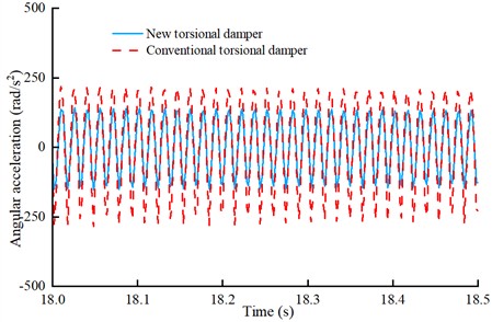
Under the combined drive conditions, the torsional damper provides small hysteresis H1, and the angular acceleration fluctuation at the E-CVT end is shown in Fig. 12.
Under combined drive conditions, the angular acceleration fluctuation was reduced from 237 rad/s2 to 189 rad/s2, representing a 20.2 % reduction compared to the conventional damper.
In summary, the newly designed variable hysteresis torsional damper can better attenuate the torsional vibration of the HEV powertrain.
Fig. 12Angular velocity fluctuations under combined drive conditions
3.2. Experimental results and discussion
To verify the performance of the newly designed variable hysteresis torsional damper, the torsional characteristics are tested by using test equipment, which is in accordance with the automotive industry standard QC/T 27-2014, “Bench Test Methods for Automotive Dry Friction Clutch Assemblies.” The torsional damper is fixed on the mandrel of the test rig, as shown in Fig. 13.
Fig. 13Torsional damper test equipment
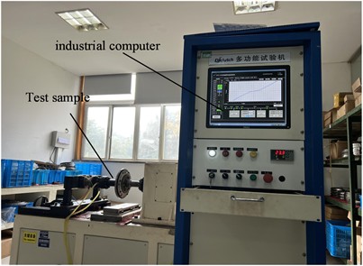
During the test, forward and reverse torque values were recorded in real-time by a torque sensor at the transmission end. The reverse torsional process was loaded slowly and then rapidly, while the forward process was unloaded quickly and then gradually. This procedure was repeated 2-3 times to simulate power transmission between the follower plate and the transmission, with the final forward and reverse torque values recorded. The torsional characteristic curve of the torsional damper, derived from multiple measurement cycles, is shown in Fig. 14.
The test results confirm that the designed torsional damper exhibits two-stage elastic torsional stiffness, with a torsion limiting torque of approximately 220 Nm, and that the measured hysteresis torque falls within the expected design range.
Fig. 14Torsional characteristic curve
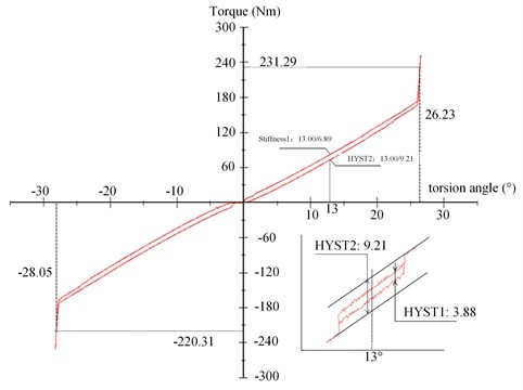
To verify the torsional characteristic parameters of the torsional damper sample, the tests were conducted to measure the hysteresis torques at specific angles, with results summarized in Table 4.
The measured results indicate that the primary and secondary hysteresis torque values are within the design specifications, confirming that the newly designed variable damping torsional damper meets the design requirements for effective vibration damping in HEV.
Table 4Hysteresis torque obtained by the test.
Level | Measuring position | Measured value (Nm) | Design range (Nm) |
First-order hysteresis | 2.9° ± 0.3°cycle | 3.88 | 2.24 - 4.16 |
Second-order hysteresis | 13° | 9.21 | 6.3 - 11.7 |
4. Conclusions
This study investigates the damping performance of the torsional damper under different damping values by simulation analysis under two modes of starting engine condition and combined drive condition, and designs a variable damping torsional damper. Finally, the performance of the designed variable damping torsional damper is verified by simulation analysis and test, and the following conclusions are obtained, which can provide an important basis for the design of the torsional damper:
1) The damping performance of the torsional damper with different hysteresis torque values is comparatively analysed by studying the damping characteristics of the torsional damper. The results show that when the damping spring of the torsional damper is compressed in the positive direction, a smaller hysteresis torque value should be selected; When the torsional damper is compressed in the negative direction, the hysteresis torque value should be adjusted in the direction of large.
2) Through simulation verification, the angular acceleration fluctuation at both ends of the torsional damper is reduced by 54.5 % in the motor-assisted engine starting conditions, and the angular acceleration is reduced by 20.2 % in the combined driving conditions, compared to a conventional damper configuration.
3) Experimental testing confirmed that the torsional characteristics of the newly designed variable damping torsional damper align closely with the calculated values. The hysteresis torques for both first-order and second-order hysteresis fall within the design range.
In summary, the variable hysteresis torsional damper proposed in this study offers a practical solution to the complex torsional vibration challenges in hybrid electric vehicles, delivering improved performance across varying driving conditions. This research lays a foundation for the future development and optimization of torsional dampers.
References
-
K. Govindswamy, T. Wellmann, and G. Eisele, “Aspects of NVH integration in hybrid vehicles,” SAE International Journal of Passenger Cars – Mechanical Systems, Vol. 2, No. 1, pp. 1396–1405, May 2009, https://doi.org/10.4271/2009-01-2085
-
Z. Yan, D. Yin, N. Zhang, and L. Chen, “Overview of vibration problems and solutions of automotive power transmission system,” Journal of Hefei University of Technology (Natural Science), Vol. 44, No. 3, pp. 289–298, Mar. 2021, https://doi.org/10.3969/j.issn.1003-5060.2021.03.001
-
Y. Qin et al., “Noise and vibration suppression in hybrid electric vehicles: State of the art and challenges,” Renewable and Sustainable Energy Reviews, Vol. 124, p. 109782, May 2020, https://doi.org/10.1016/j.rser.2020.109782
-
Q. Wang, “Survey on energy management strategy for plug-in hybrid electric vehicles,” Journal of Mechanical Engineering, Vol. 53, No. 16, pp. 1–19, Jan. 2017, https://doi.org/10.3901/jme.2017.16.001
-
H. Liu, J. Zhao, T. Qing, X. Li, and Z. Wang, “Energy consumption analysis of a parallel PHEV with different configurations based on a typical driving cycle,” Energy Reports, Vol. 7, pp. 254–265, Nov. 2021, https://doi.org/10.1016/j.egyr.2020.12.036
-
X. Tang, D. Zhang, T. Liu, A. Khajepour, H. Yu, and H. Wang, “Research on the energy control of a dual-motor hybrid vehicle during engine start-stop process,” Energy, Vol. 166, No. 1, pp. 1181–1193, Jan. 2019, https://doi.org/10.1016/j.energy.2018.10.130
-
D. Zhang, H. Yu, J. Zhang, T. Lu, and X. Tang, “Analysis and control of torsional vibration in HEV,” Drive System Technique, Vol. 28, No. 4, pp. 3–8, Dec. 2014, https://doi.org/10.3969/j.issn.1006-8244.a0772
-
J. Zhang, D. Liu, and H. Yu, “Experimental and numerical analysis for the transmission gear rattle in a power-split hybrid electric vehicle,” International Journal of Vehicle Design, Vol. 74, No. 1, pp. 1–18, Jan. 2017, https://doi.org/10.1504/ijvd.2017.084539
-
P. Gao et al., “Study on torsional isolator and absorber comprehensive vibration reduction technology for vehicle powertrain,” Journal of Mechanical Engineering, Vol. 57, No. 14, p. 244, Jan. 2021, https://doi.org/10.3901/jme.2021.14.244
-
X. Tang, X. Hu, W. Yang, and H. Yu, “Novel torsional vibration modeling and assessment of a power-split hybrid electric vehicle equipped with a dual-mass flywheel,” IEEE Transactions on Vehicular Technology, Vol. 67, No. 3, pp. 1990–2000, Mar. 2018, https://doi.org/10.1109/tvt.2017.2769084
-
H. Wu, “Design and development of three-stage stiffness clutch damper and its damping performance analysis,” Journal of Mechanical Engineering, Vol. 55, No. 4, p. 75, Jan. 2019, https://doi.org/10.3901/jme.2019.04.075
-
Z. Yan, J. Zhang, Y. Liu, and G. Hou, “Design and experimental research on damper with torque limiter in hybrid powertrain,” Automobile Technology, Vol. 6, pp. 41–46, Jun. 2021, https://doi.org/10.19620/j.cnki.1000-3703.20201203
-
Z. Yan, S. Liu, J. Zhang, G. Li, M. Yao, and N. Zhang, “Torsional characteristics optimization of a damper with a torque limiter in a hybrid electric vehicle based on multi-DOF powertrain bond graph modeling,” Mechanical Systems and Signal Processing, Vol. 222, p. 111787, Jan. 2025, https://doi.org/10.1016/j.ymssp.2024.111787
-
“Torsion damper,” CN111771072A, Schaeffler Technologies AG and Co.KG, 2020.
-
K. Wang, H. Yu, L. Zou, J. Zhang, and T. Zhang, “Resonance speed optimization analysis of driveline for hybrid electric vehicles,” Automobile Technology, Vol. 7, pp. 1–5, Nov. 2013, https://doi.org/10.3969/j.issn.1000-3703.2013.07.001
-
H.-Y. Hwang, “Minimizing seat track vibration that is caused by the automatic start/stop of an engine in a power-split hybrid electric vehicle,” Journal of Vibration and Acoustics, Vol. 135, No. 6, p. 06100, Dec. 2013, https://doi.org/10.1115/1.4023954
-
L. Chen and L. Tao, “Modeling and characteristic analysis of torsional vibration of HEV driveline excited by multi-source harmonics,” Noise and Vibration Control, Vol. 43, No. 6, pp. 1–7, Jul. 2023.
-
S. Wang, Q. Zhang, D. Shi, C. Yin, and C. Li., “Analysis of nonlinear vibration response characteristics of hybridtransmission system with dual-planetary gear sets,” Journal of Jilin University (Engineering and Technology Edition), Vol. 54, No. 4, pp. 890–901, Dec. 2024, https://doi.org/10.13229/j.cnki.jdxbgxb.20221107
-
L. Li and R. Singh, “Start-up transient vibration analysis of a vehicle powertrain system equipped with a nonlinear clutch damper,” SAE International Journal of Passenger Cars – Mechanical Systems, Vol. 8, No. 2, pp. 726–732, Jun. 2015, https://doi.org/10.4271/2015-01-2179
-
L. Li and R. Singh, “Analysis of start-up transient for a powertrain system with a nonlinear clutch damper,” Mechanical Systems and Signal Processing, Vol. 62-63, pp. 460–479, Oct. 2015, https://doi.org/10.1016/j.ymssp.2015.03.001
-
L. Zhang, Z. Wang, C. Ren, and X. Fang, “Innovation design and application of speed-increasing clutch for hybrid electric vehicle,” Journal of Mechanical Engineering, Vol. 59, No. 8, p. 253, Jan. 2023, https://doi.org/10.3901/jme.2023.08.253
-
H. Yang, B. Kim, Y. Park, W. Lim, and S. Cha, “Analysis of planetary gear hybrid powertrain system part 2: Output split system,” International Journal of Automotive Technology, Vol. 10, No. 3, pp. 381–390, Jun. 2009, https://doi.org/10.1007/s12239-009-0044-y
-
D. Shi, X. Rong, S. Wang, K. Zhang, L. Chen, and C. Li, “Research on the optimal dynamic coordinated control of power split hybrid electric vehicles with dual-clutch collaboration,” Automotive Engineering, Vol. 44, No. 12, pp. 1877–1888, Dec. 2022, https://doi.org/10.19562/j.chinasae.qcgc.2022.12.009
-
K. Huang, Z. Jin, and Y. Zhang, “Start/stop control of hybrid electric vehicle engine,” Vehicle Engine, Vol. 4, pp. 45–48, Aug. 2006.
-
W. Shangguan, T. Sun, R. Zheng, J. Xie, S. Wang, and Q. Hou, “Research on the influence of clutch driven disc performance on vehicle starting jitter,” Journal of Vibration Engineering, Vol. 29, No. 3, pp. 488–497, Jun. 2016, https://doi.org/10.16385/j.cnki.issn.1004-4523.2016.03.015
-
R. Shaver, Manual Transmission Clutch Systems AE-17. United States: SAE International, 1997.
About this article
The authors wish to acknowledge the Open Project of state Key Laboratory of Engine and Powertrain System in 2023 (No. skleps-sq-2023-018) for the financial support of this research.
The datasets generated during and/or analyzed during the current study are available from the corresponding author on reasonable request.
Zhongye Zhang wrote the manuscript. Xumao Zhai, Shibo Cheng and Zhiyong Wen performed the experiments and processed the data. Mingyao Yao and Zhengfeng Yan reviewed the manuscript.
The authors declare that they have no conflict of interest.

