Abstract
The torsional vibration of the shaft system in hybrid car engines has a significant impact on the overall performance of the vehicle, and it is more complex in hybrid cars compared to traditional cars. Traditional methods for torsional vibration analysis of shaft systems have significant limitations and cannot handle nonlinear and transient problems. To explore the torsional vibration characteristics of hybrid vehicle shaft systems, a simplified engine shaft system torsional vibration equivalent model is innovatively constructed. In addition, a method for quickly determining the confidence level of the torsional vibration equivalent model is proposed. Additionally, the transient dynamic characteristics of a multi-body dynamics model containing a dual mass flywheel are analyzed in depth using the time-domain solver of AVL-exact PU. The results demonstrated that the simulation of 4th and 6th harmonics resonated at critical speeds of 4,195 rpm and 2,771 rpm, respectively, with angular displacement amplitudes of 0.141 deg and 0.047 deg. In fact, resonance was measured at 4,250 rpm and 3,040 rpm, with amplitudes of 0.14 deg and 0.052 deg. These two were basically consistent in key parameters. When the shaft model was started under operating conditions, the amplitudes of harmonics 1, 2, and 4 were basically consistent below 750 rpm, and there were slight differences after 750 rpm. Therefore, the AVL-based engine torsional vibration simulation model constructed has high credibility.
1. Introduction
With the gradual strengthening of environmental awareness in modern society, people are more inclined towards energy-saving and environmentally friendly hybrid vehicles in their vehicle selection [1]. Hybrid electric vehicles integrate engines and electric drive to achieve power and range advantages, while reducing energy consumption and carbon emissions [2]. As an important component of hybrid power systems, the engine inevitably generates shaft torsional vibration during operation, which causes trouble to the hybrid electric vehicles’ stable performance [3]. Shaft torsional vibration not only affects the efficiency of energy transfer, but also directly affects the noise, vibration, and comfort of the power system. Additionally, the shaft torsional vibration of hybrid electric vehicles is more complex, so effective control of them is crucial [4]. The commonly used shaft torsional vibration research method is the frequency domain analysis, which has limitations in dealing with nonlinear problems and transient processes. Time domain analysis can provide a more intuitive torsional vibration time response, which is conducive to capturing the dynamic characteristics during transient processes. In addition, AVL-excite PU (AVL) is an advanced multi-body dynamics simulation tool specifically designed for 3D fine modeling of complex components, particularly favored in system dynamics, vibration, and structural noise analysis. In view of this, to deepen the understanding of the shaft torsional vibration characteristics of hybrid electric vehicles, this study proposes an engine shaft model based on AVL and its dynamic time-domain analysis method.
The innovation and novelty of this study are mainly reflected in the following aspects: Firstly, the complex engine shaft structure of hybrid vehicles has been simplified, and the feasibility and efficiency of analysis have been improved by constructing an equivalent model of engine shaft torsional vibration. Secondly, a quick discrimination of torsional equivalent model confidence (QDTEMC) method is proposed to reduce excessive reliance on computational accuracy and enhance the practical application value of the model. Finally, with the help of the time-domain solver of AVL, the dynamic characteristics of the shaft system during transient processes are analyzed in depth. Meanwhile, a multi-body dynamic model including a dual mass flywheel (DMF) is developed to provide more accurate dynamic behavior prediction.
The content has four parts: (1) The part of related work analyzes the current status of shaft torsional vibration research methods and AVL analysis software. (2) The method part proposes engine shaft model and dynamic time-domain analysis method methods based on AVL. (3) The experimental part performs torsional vibration analysis on the established model. (4) The conclusion part summarizes the entire article and provides an outlook.
2. Related work
The research on torsional vibration analysis focuses on improving simulation accuracy and developing advanced experimental measurement techniques, and many scholars have contributed to this. Peng Y and other researchers have studied the torsional vibration problem caused by rolling mill shaft deflection and proposed a new solution. This scheme was based on a nonlinear dynamic model of torsional vibration, analyzing the variation law of torque during torsional vibration, and combining numerical simulation to reveal the relationship between periodic excitation energy and tension friction torque. The reliability of the constructed model has been verified, providing an improvement direction for the shaft torsional vibration problem of the rolling mill transmission system [5]. Wang M. et al. proposed an accurate method for evaluating the dynamic characteristics of crankshaft systems in response to torsional vibration problems. This method utilized ADAMS software to establish a three-dimensional multi-body dynamics model for components such as pistons, connecting rods, crankshafts, flywheels, and silicone oil dampers, and conducted finite element analysis. Finally, it was compared with the experimental data of the engine crankshaft system, confirming the correctness and practical application value of the proposed method [6]. Chen and other scholars have proposed a new solution to the shaft torsional vibration problem that occurs in shale gas wells under complex geological conditions. It took the shale gas well in Weiyuan gas field as the typical case, constructed a complete dynamic shaft torsional vibration system under cyclic alternating load, and verified the accuracy of the model through on-site vibration experiments. At the same time, the response surface way was utilized to optimize the shaft structure. It was found that the first natural frequency of the shaft system increased by 4.5 % before and after optimization, and the maximum vertical speed decreased by 27.7 %, effectively extending the working life of the system [7]. To improve the accuracy of diesel engine shaft structure, researchers such as Ni proposed a method based on multi-physics field coupling modeling. On this basis, a mathematical model of the shaft system of the 4190ZL-C medium speed diesel engine was established using the Simulink platform, and coupled simulation was conducted on the fuel injection advance angle and torsional vibration. Compared to traditional simulation methods, this method further improved the shaft torsional vibration model, improved its modeling accuracy, and provided new theoretical support for engine structural optimization design [8].
AVL analysis software has extensive research in the fields of system dynamics, vibration, and structural noise analysis. Wu et al. studied a 20V medium speed diesel engine and established a multi-elastic liquid water solid coupling numerical simulation method using AVL software to study the friction and wear characteristics of the main bearing sleeve of the 20V diesel engine. This method used the finite element modal condensation method to simulate the elastic deformation of the cylinder block, crankshaft, and bearing cover, and combined it with the extended Reynolds equation considering contact surface deformation. The finite difference method was adopted to analyze the oil film pressure, thickness, and thermal load. By reducing the stiffness of the bearing cover edge, the maximum oil film pressure and the mean thermal load of the main bearing could be effectively reduced [9]. To solve the problem of engine crankshaft torsional vibration, Sezgen and Tinkir optimized the design using AVL software. This method combined dual particle rubber with viscous torsional dampers and optimized the dynamic damping characteristics of a four stroke diesel engine crankshaft system using genetic algorithm. Simulation showed that this method reduced torsional vibration by 50.17 % and had a significant improvement effect [10]. Almansoori et al. used a multi-objective optimization algorithm and combined AVL Excite Piston & Rings dynamic simulation software with the mode FRONTIER optimizer to study the operating characteristics of internal combustion engine piston ring groups. On this basis, the SS-ANOVA statistical modeling method was used to study the sensitivity of three types of piston ring tangential forces under single and interaction effects. After verification, there was a good correlation between the simulation results and the measured values, which proved the accuracy of the proposed model [11]. Li et al. used the AVL-EXCITE platform to accurately characterize the cavitation phenomenon inside the connecting rod bearings of diesel engines. This study focused on elastohydrodynamic lubrication, constructed its multi-body dynamics model, and conducted numerical simulation on elastohydrodynamic lubrication. There was a finger-shaped cavitation zone at the lubrication outlet of the connecting rod large end bearing, which posed a risk of inducing cavitation. In addition, the study also analyzed the effects of factors such as lubricant viscosity and supply pressure on cavitation performance, and pointed out that increasing these two parameters can effectively alleviate cavitation phenomenon [12].
In summary, there have been many research results on the torsional vibration analysis methods, and the application fields of AVL software are also quite extensive. However, there is still significant room for development in the study of shaft torsional vibration analysis of hybrid electric vehicles, and few scholars have discussed this and explored the dynamic characteristics of the shaft torsional vibration system of hybrid electric vehicles using AVL time-domain analysis. Therefore, this study proposes an engine shaft model and its dynamic time-domain analysis method method based on AVL to further deepen the understanding of the shaft torsional vibration characteristics of hybrid electric vehicles.
3. Engine shaft model construction and dynamic time-domain analysis method based on AVL
This section starts from two aspects. Firstly, an equivalent model of the engine shaft system is constructed built on AVL, and its confidence evaluation methods are optimized. On this basis, a calculation method for the dynamic characteristics of engine shaft systems based on AVL time-domain analysis is constructed, and a multi-body dynamics model with DMF is established.
3.1. Establishment of engine shaft torsional vibration equivalent model based on AVL
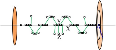
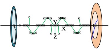
The actual structure of hybrid electric vehicles engines is relatively complex. To facilitate calculation and modeling, it is needed to simplify the complex structure and convert it into a more concise and clear equivalent model. Afterwards, the equivalent model can be further transformed into a numerical model for theoretical calculations [13]. During this process, the equivalent torsional vibration system should have the same torsional vibration dynamic characteristics as the actual equivalent torsional vibration system. To ensure that the equivalent torsional vibration system can accurately reflect the torsional vibration dynamic characteristics of the crankshaft, it is necessary to minimize the error between the equivalent torsional vibration system and the original equivalent torsional vibration system in terms of kinetic energy and potential energy to maintain consistency in their dynamic behaviors of torsional vibration [14-15]. Fig. 1 shows the actual geometric model of the crankshaft and its equivalent model.
The equivalent model parameters of the shaft system include the moment of inertia of the concentrated mass point, torsional stiffness of the elastic shaft segment, and equivalent model damping [16-17]. Among them, for the axis segment with regular shape and the center of gyration located at its center of mass, the inertia of its concentrated mass point is Eq. (1):
where, represents the mass of any particle on the rigid body. represents the radius of rotation of the concentrated particle relative to the axis of rotation. The torque applied by an object to produce unit radian deformation under external forces is characterized by torsional stiffness [18]. For shaft segments with regular shapes, the calculation of torsional stiffness of the elastic shaft segment is Eq. (2):
where, is the moment of inertia of the concentrated mass point about its center of mass. represents the mass of the mass point. represents the distance between the center of mass of the mass point and the axis of rotation. The torsional stiffness of a regularly shaped shaft segment is expressed as Eq. (3):
where, represents the torque acting on the object. represents the relative torsion angle generated by the object. is the shear elastic modulus of the object material. represents the polar moment of inertia of the cross-section. is the length of the shaft segment. The damping of the engine crankshaft system is divided into external and internal damping. In torsional vibration analysis, internal damping refers to structural damping, and external damping refers to cylinder damping. The equivalent model damping is shown in Eq. (4):
where, represents the cylinder diameter. represents stroke. According to Newton's second law, considering the data of moment of inertia and torsional stiffness, combined with the cylinder diameter and stroke , they are substituted into the differential equation to analyze the expression of damping value . The coefficient of 3.98×10⁻⁸ is determined by professional engineers or researchers based on physical principles and experimental data analysis, which is based on system characteristics and experimental results. After obtaining the rotational inertia and torsional stiffness data of each concentrated mass point on the crankshaft, an equivalent torsional vibration model can be constructed. The model construction follows Newton’s second law and can derive the differential equation of crankshaft torsional vibration, as shown in Eq. (5):
where, represents the moment of inertia matrix of each concentrated mass point. means the damping matrix of the system. represents the stiffness matrix of the equivalent torsional vibration system. The analysis of free vibration of crankshaft torsional vibration can reveal its inherent torsional vibration characteristics, and thus calculating the natural frequency and vibration mode [19]. The mathematical differential equation is Eq. (6):
where, represents the displacement vector of the system. represents the first-order time derivative of the displacement vector. represents the second-order time derivative of the displacement vector. Solving Eq. (6) can obtain the eigenvalues and eigenvectors of the system. Due to the existence of indefinite solutions to the system of equations, it is necessary to supplement the equations to ensure the uniqueness of the solutions. Usually, the first mass amplitude is selected as the reference, and the relative amplitudes of each degree of freedom are calculated to form a unique solution, as shown in Eq. (7):
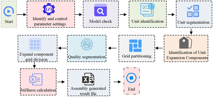
where, ,…, and , ,…, represent the absolute and relative values of displacement amplitudes for each degree of freedom. The core of torsional vibration analysis lies in using an equivalent model to accurately capture the dynamic characteristics of the actual crankshaft. This process involves discretizing the continuous crankshaft structure into a multi-body system with equivalent mass and elasticity, and establishing dynamic differential equations based on this. In torsional vibration analysis, the simulation of the dynamic response capability of the engine crankshaft and related rotating components is mainly achieved through AVL. AVL abstracts the solid crankshaft as a high-precision discrete equivalent model, establishes corresponding dynamic differential equations, and enables it to accurately simulate and analyze the dynamic response of free vibration and forced vibration [20]. The ShaftModeler module of AVL, equipped with an Autoshift pre-processing program, mainly performs automatic recognition, segmentation, and meshing of the crankshaft model. After importing the model, the program automatically performs quality and stiffness analysis, and outputs a CFF file and processed crankshaft model. Fig. 2 displays the identifying process of the crankshaft using Autoshift.
Fig. 1Actual geometric model of crankshaft and its equivalent model
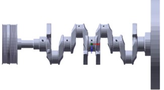
a) Actual crankshaft system
b) Equivalent model of crankshaft
Fig. 2Autoshift recognition of crankshaft process
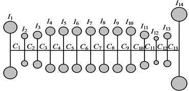
After the crankshaft model is built, AVL software will simplify the shaft system model based on reduction rules, forming a torsional equivalent model composed of mass points and rigid shaft segments. Fig. 3 shows the equivalent torsional vibration model of the crankshaft optical axis, crankshaft with pulley, and crankshaft with vibration damper. In the Fig. 3, the pulley and damper are respectively reduced to single and double mass discs to simulate their dynamic effects.
Fig. 3Torsional equivalent model of crankshaft optical axis, crankshaft with pulley, and crankshaft with vibration damper
a) Equivalent model of crankshaft optical axis torsional vibration
b) ETVS model of crankshaft with pulley
c) ETVS model of crankshaft with vibration damper
The model confidence can measure the consistency between the parameters, boundary conditions, and actual system behavior of the torsional equivalent model, and is the key to the authenticity of forced torsional vibration analysis [21]. However, the traditional lumped parameter method relies on experimental verification of calculation accuracy and lacks fast and effective confidence evaluation methods. Therefore, this study proposes a QDTEMC method, which mainly compares multi-level modal data to quickly verify the confidence of the torsional vibration model. Specifically, QDTEMC verifies the confidence of the torsional equivalent model by comparing the multi-stage modal of the crankshaft, mainly involving three models: optical axis, crankshaft with pulley, and crankshaft with vibration damper. It eliminates randomness in the confidence verification process by reflecting different inertia, stiffness, and nonlinear characteristics. The 3D mode obtained from Ansys finite element calculation of the crankshaft model is compared with the torsional vibration mode of ShaftModeler. If the difference is within the allowable range, that is, the model has high confidence and is suitable for subsequent forced vibration analysis, while models with lower confidence are rejected for improvement.
3.2. A calculation method for dynamic characteristics of engine shafting based on AVL time-domain analysis
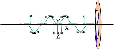
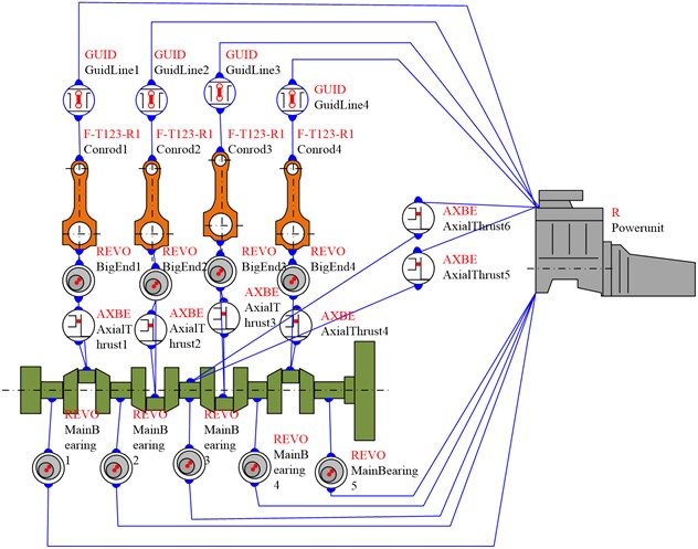
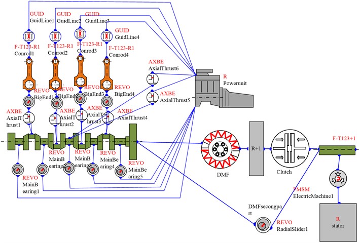
After constructing the equivalent model of crankshaft torsional vibration, the connecting rod and body components are introduced into the PU interface of AVL, and the connection relationships between the connecting rod and the crankshaft pin, the connecting rod and the body, and the main journal and the body are precisely defined, that is, each connecting pair [22]. Fig. 4 shows the complete engine system multi-body dynamics model. This model can simulate and analyze the forced vibration behavior of the engine shaft system under operating conditions, which helps to analyze the dynamic performance of the engine.
This study focuses on the shaft torsional vibration characteristics of hybrid electric vehicle engines and explores the unique vibration behavior under the coupling of motors and engines. The hybrid system frequently adjusts the driving mode to optimize fuel efficiency, so the torsional vibration dynamic characteristics of the shaft system under transient conditions have become a research focus. This study analyzes the impact of motor transient excitation on shaft torsional vibration during start-up and rapid acceleration conditions after constructing the power system multi-body dynamics model. During the transient process of the power-train, the load boundary conditions constantly change, so a time-domain solver is needed to simulate the dynamic characteristics of the power-train. The AVL-Time Domain Solution (AVL-TDS) carried by AVL adopts an adaptive integration algorithm, which can accurately calculate the torsional vibration dynamic characteristics of the shaft system during transient processes [23].
Fig. 4A complete multi-body dynamics model of the engine system
The equation of multi-body dynamics vibration is Eq. (8):
where, , , represent the inertia matrix, damping matrix, and stiffness matrix of the power-train system, respectively. , , represent the acceleration, velocity, and displacement vectors at time step . , , , represent the external load, connecting force, inertial force, and gyroscopic force at time step . AVL uses the Lagrange finite difference method to transform Eq. (7) into the interpolation polynomial shown in Eq. (8) when conducting time-domain analysis of the multi-body dynamics system of the power-train:
where, represents the first derivative of the Lagrangian operator, and its specific expression is Eq. (10):
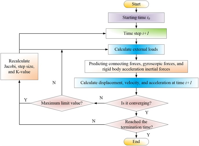
When performing transient simulation analysis in AVL software, after completing one time step of simulation analysis, the adaptive integration algorithm is used for the next step of time-domain solution calculation until each time step of the entire transient process is calculated. Fig. 5 shows the transient calculation process based on AVL-TDS.
Fig. 5Transient calculation process based on AVL-TDS
To optimize the vibration reduction and isolation control of the hybrid shaft system and to isolate engine excitation disturbances from the rear end transmission system, this study proposes the use of DMF to improve shaft vibration. DMF is optimized based on Single Mass Flywheel (SMF). DMF divides SMF into two parts and increases its moment of inertia without increasing the mass on the transmission side, which helps to reduce the resonance speed of the shaft system. Based on the simplified AVL two degree of freedom torsional vibration model, the forced vibration differential equation is established, as shown in Eq. (11):
where, , represent the moment of inertia of the primary and secondary mass parts of DMF, respectively. , represent the torsional displacement of two mass parts , . represents the torsional stiffness of the DMF spring. represents the DMF damping coefficient. represents sinusoidal excitation of the engine crankshaft. represents the frequency of the excitation circle. In the process of solving the system of equations, the angular displacement frequency response relationship of DMF torsional vibration is involved, as shown in Eq. (12):
Correspondingly, the differential equation for forced vibration of the SMF wheel is Eq. (13):
where, is the rotational inertia of the flywheel. is the displacement of the flywheel torsion angle. The angular displacement frequency response relationship of SMF torsional vibration is Eq. (14):
DMF has key parameters such as moment of inertia ratio, inertia characteristics, and damping characteristics. The natural frequency of a two degree of freedom system connected by springs is Eq. (15):
Fig. 6Multi-body dynamics model with DMF
In the hybrid electric vehicle axis system dynamics, this study constructs a multi-body dynamics model with DMF, as shown in Fig. 6. This model aims to explore in depth the influence of DMF integration on the transient torsional vibration behavior of shaft systems. The study selects the rapid acceleration condition of the engine as the specific scenario and simulates the dynamic response of the engine when the load changes sharply. The introduction of DMF aims to improve torsional vibration characteristics, reduce peak torque transmission, and slow down vibration propagation.
4. Simulation analysis of engine shaft model dynamic characteristics based on AVL
This section first conducts simulation analysis on the forced vibration of the engine crankshaft to verify the accuracy of the Engine Torsional Vibration (ETV) simulation model. Afterwards, this study conducts torsional vibration analysis and vibration reduction control analysis of engine shaft model, and proposes relevant control strategies.
4.1. Analysis of forced vibration of engine crankshaft
This study takes a 2.0L four cylinder gasoline engine as an example. Before conducting simulation experiments on forced vibration analysis of engine crankshafts, the simulation parameters are first controlled. The combustion force inside the engine cylinder is transmitted to the crankshaft through the cylinder pressure curve, causing a periodic and complex excitation torque that can be decomposed into the sum of multiple harmonic functions. As the harmonic excitation increases, the excitation amplitude decreases, and the energy input decreases, therefore, the focus is on low harmonic excitation. In a multi-cylinder engine, there is a phase difference in the th harmonic excitation torque on the crankshaft. If the phase difference is a multiple of 360°, it will trigger the main resonance. The firing interval angle of a four cylinder engine is 180°, and the main resonance harmonics are 2, 4, 6, 8, and 10. Therefore, this study prioritizes analyzing the amplitude curves caused by these harmonics. During the measurement process of engine shaft torsion test, a high-precision torsion angle sensor is first installed at the front end of the crankshaft to obtain accurate vibration data. When the engine is running, the pressure inside the cylinder is transmitted to the crankshaft through combustion force, and the torsional vibration caused is recorded in real-time by the sensor. The data records encompass the entire speed range. By comparing multiple harmonic vibration data sets, the focus is on analyzing the torsional angular displacement amplitude of low-order harmonics, specifically 2, 4, and 6. The measurement results are compared with simulation data to verify the accuracy of the simulation model. In the comparative analysis of modal data, the study verifies the natural frequencies and vibration modes of the crankshaft with different harmonics through the comparison of simulation and measured data. The modal data utilized in comparative research encompasses essential parameters such as natural frequency and damping ratio, which serve to validate the reliability and precision of the simulation model.
Fig. 7Amplitude curves of torsional vibration angle displacement for each harmonic at the FEoC
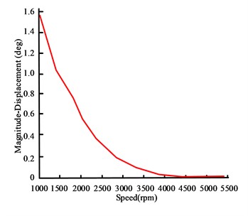
a) 2-harmonic amplitude curve
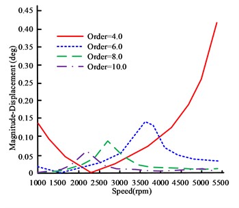
b) 4, 6, 8, and 10 harmonic amplitude curves
In Fig. 7, in the low speed region, the amplitude of the 2nd harmonic is relatively large, mainly due to the occurrence of rolling vibration. Rolling vibration has no relative torsion and poses little harm to the crankshaft. At high speeds, the second harmonic frequency is low, making it difficult to resonate with the natural frequency of the crankshaft, resulting in a smaller amplitude. The angular displacement of 4th and 6th harmonics reaches 0.42° and 0.14° respectively at 5400 rpm and 3610 rpm, exceeding the industry standard limit of 0.1°. Although resonance occurs at 10 harmonics, the critical speeds are 2720 rpm and 2210 rpm, respectively, and the peak amplitude is below the safety limit. Therefore, the amplitudes of harmonics 4 and 6 exceed the safety standards and require vibration reduction control.
Fig. 8Comparison results between simulated and measured amplitude curves of 4 and 6 harmonics
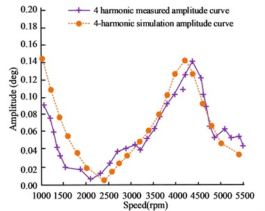
a) 4-harmonic angular displacement amplitude curve
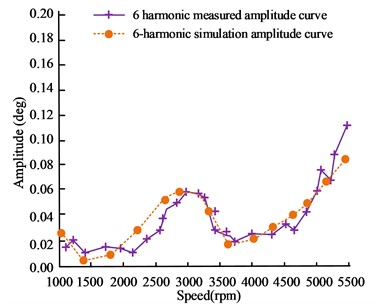
b) 6-harmonic angular displacement amplitude curve
In Fig. 8, the simulated and measured values of the amplitude curves of the 4th and 6th harmonic angular displacement show consistent trends and resonance peaks. The 4-harmonic simulation resonates at a critical speed of 4195 rpm, with an angular displacement amplitude of 0.141 deg. The measured resonance occurs at 4250 rpm, with an amplitude of 0.14 deg. The 6-harmonic simulation resonates at 2771 rpm with an amplitude of 0.047 deg, while the actual measurement resonates at 3040 rpm with an amplitude of 0.052 deg. The curve trend in the graph shows that the two are basically consistent in key parameters. This result indicates that the AVL-based engine torsional vibration simulation model constructed has high accuracy. In addition, this result also confirms the effectiveness of the QDTEMC confidence method for the torsional equivalent model.
4.2. Engine shaft model torsional vibration analysis and vibration reduction control analysis
This study takes hybrid electric vehicles engines as an example to investigate their torsional vibration characteristics under different operating conditions. Compared to gasoline vehicles, the hybrid system adopts a completely new power source. Due to the different working characteristics of motors and engines, their vibration characteristics are also not the same. When the two are coupled with each other, the hybrid system will exhibit new features that are different from conventional fuel vehicles. In addition, hybrid vehicles need to adapt to the actual driving environment and continuously adjust the driving mode to ensure that they operate within the optimal fuel consumption range. Therefore, the shaft torsional vibration characteristics vary under various transient operating conditions. This study analyzes the impact of transient excitation of the motor on the shaft torsional vibration characteristics of the engine under the starting and rapid acceleration conditions of hybrid vehicles.
In Fig. 9(a), the 0.5 harmonic amplitude curve perfectly matches the measurement points at the Front End of the Crankshaft (FEoC), the second to fourth main journals, and the flywheel end, indicating that the 0.5 harmonic vibration during the startup process belongs to rolling vibration phenomenon and does not cause relative torsion of the crankshaft. Under steady-state conditions, the small amplitude of 0.5 harmonics indicates that the significant vibration comes from the transient process of engine speed changes. In Figs. 9(b) and 9(c), the amplitudes of the 1st and 2nd harmonics are basically consistent below 750 rpm, and there are slight differences after 750 rpm. Therefore, it can also be considered that they are mainly caused by rolling vibration. In Fig. 9(d), the amplitude of the four harmonics is consistent before 750 rpm, and there is a slight torsional vibration after 750 rpm. The amplitude decreases as the speed increases, and the vibration becomes stronger at low speeds, which is related to the rate of speed change during the low speed stage under constant acceleration starting conditions. Therefore, the vibration under the starting condition is mainly caused by rolling vibration, with slight and low amplitude torsional vibration, indicating that the torsional vibration of the shaft system is less harmful under this condition.
Fig. 9Comparison results of amplitude curves of different harmonics of the shaft system model during start-up conditions
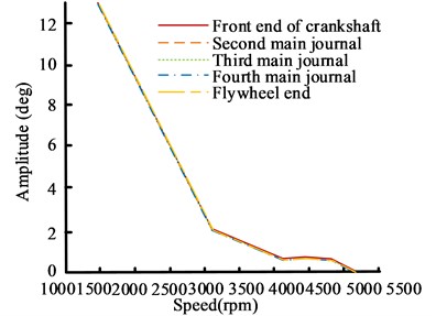
a) 0.5 harmonic amplitude curve
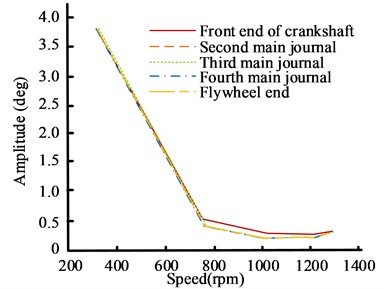
b) 1 harmonic amplitude curve
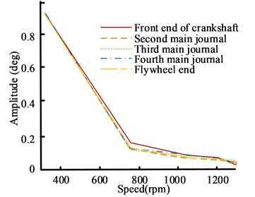
c) 2 harmonic amplitude curve
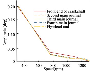
d) 4 harmonic amplitude curve
To investigate the effect of motor excitation on shaft torsional vibration, the 4th and 6th harmonic amplitude curves of the hybrid shaft system under rapid acceleration conditions and pure engine full load steady-state conditions are compared, as shown in Fig. 10. In Fig. 10, the amplitudes of the 4th and 6th harmonics during rapid acceleration are slightly higher than the steady-state operating conditions, but the difference between the two is subtle. Based on the phenomenon of less obvious torsional vibration under starting conditions, it can be inferred that the influence of motor excitation on shaft torsional vibration characteristics is relatively limited, and the influence on rolling vibration is more significant. Under the same torque output conditions, the torsional vibration intensity excited by the engine exceeds that of the motor. Based on this characteristic, the active control strategy of the shaft torsional vibration can be achieved by adjusting the power output of the motor and engine in real time, optimizing the dynamic performance of the hybrid shaft system.
Fig. 10Comparison of amplitude curves between hybrid shaft system under rapid acceleration and pure engine steady-state conditions
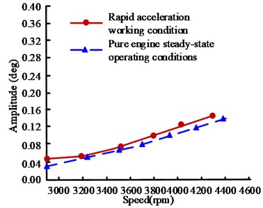
a) Comparison of 4-harmonic amplitude curves
b) Comparison of 4-harmonic amplitude curves
Fig. 11Comparison results of 4 and 6 harmonic amplitude curves
a) 4-harmonic amplitude
b) 6-harmonic amplitude
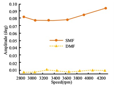
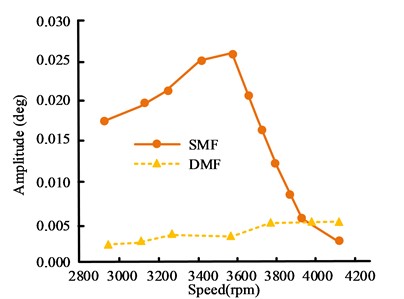
Fig. 11 is the results of the 4th and 6th harmonic amplitude curves when DMF is installed at the motor rotor and the original SMF is maintained. In Fig. 11, after the installation of DMF, the amplitude fluctuation range of the 4th harmonic at the motor rotor is between 0.003 and 0.0015, while the original amplitude fluctuation range of SMF is between 0.07 and 0.10. The amplitude fluctuation range of 6 harmonics at the motor rotor is between 0.002 and 0.005, and the amplitude fluctuation range of SMF is between 0.002 and 0.026, which is relatively large and unstable. Therefore, under rapid acceleration conditions, after the installation of DMF, the 4th and 6th harmonic torsional vibration amplitudes at the motor rotor are much smaller than the original SMF. As a result, the installation of DMF not only reduces the speed fluctuation of the secondary flywheel rear end transmission components, but also reduces the torsional angular displacement amplitude of the rear end transmission components.
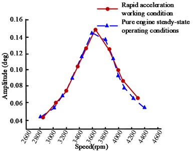
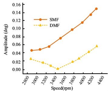
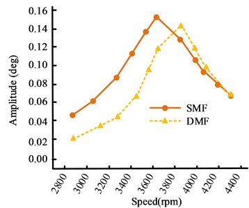
Fig. 12 is the comparison of the amplitude curves of the 4th and 6th main harmonic torsional vibrations when DMF and SMF are installed at the FEoC. Compared to SMF, the installation of DMF significantly reduces the 4th harmonic amplitude at the FEoC, while the peak amplitude of the 6th harmonic amplitude slightly decreases. At some speeds, the torsional vibration amplitude exceeds 0.1°, but the range of excessively high amplitudes is reduced. The reason for the above changes is that DMF reduces the speed fluctuation of the secondary flywheel rear end and increases the speed fluctuation of the front crankshaft. Secondly, the damping characteristics of DMF and the lower moment of inertia of the primary flywheel increase the natural frequency of the system, leading to an increase in resonance speed and effectively suppressing torsional vibration amplitude. Therefore, DMF significantly reduces the speed fluctuation and torsional displacement of the transmission system, improves the smoothness of operation and noise reduction effect, but enhances the speed fluctuation of the front crankshaft of the primary flywheel.
Fig. 12Comparison results of 4th and 6th harmonic amplitude curves at the FEoC
a) 4-harmonic amplitude
b) 6-harmonic amplitude
To further verify the practical application effect, simulation is conducted on the speed fluctuations of DMF and SMF under rapid acceleration conditions, and the results are shown in Fig. 13. The graph shows that the speed fluctuation of SMF is almost negligible in DMF under rapid acceleration conditions. After the installation of DMF, the engine excitation disturbance can be well isolated from the transmission system after being transmitted to the secondary flywheel, allowing the rear transmission components to operate more smoothly and reducing their vibration noise. Conversely, this will also exacerbate the speed fluctuation of the crankshaft prior to the primary flywheel. This is because compared to the original SMF, the primary flywheel has a smaller moment of inertia and a lower inhibitory effect on speed fluctuation.
Fig. 13Comparison of speed fluctuations between DMF and SMF under rapid acceleration conditions
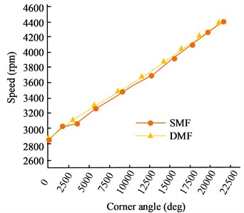
a) The speed fluctuation during the entire rapid acceleration process
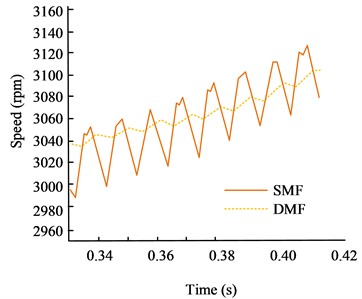
b) Local speed fluctuations during rapid acceleration
5. Conclusions
Under the trend of environmental protection, hybrid electric vehicles are highly favored due to their integration of engine and electric drive efficiency and low emissions. The inherent shaft torsional vibration problem of the engine poses a challenge to the performance of hybrid electric vehicles, and its complexity requires precise control strategies to optimize the overall power system performance. To understand the characteristics of hybrid electric vehicles shaft torsional vibration, this study proposed an engine shaft model and its dynamic time-domain analysis method based on AVL. This study conducted simulation analysis and the data showed that in the forced vibration analysis of the engine crankshaft, the angular displacement of the 4th and 6th harmonics reached 0.42° and 0.14° respectively at 5400 rpm and 3610 rpm, exceeding the industry standard limit of 0.1°. The 4th and 6th harmonic simulations resonated at critical speeds of 4195 rpm and 2771 rpm, with angular displacement amplitudes of 0.141 deg and 0.047 deg. The resonance was measured at 4250 rpm and 3040 rpm, with amplitudes of 0.14 deg and 0.052 deg, and the simulation values were in good agreement with the measured values. When the shaft system model started, the 1st, 2nd, and 4th harmonics were basically consistent below 750 rpm, but there were slight differences after 750 rpm. The vibration under this working condition was mainly caused by rolling vibration. During rapid acceleration, the amplitude of the 4th and 6th harmonics was slightly higher than the steady-state operating states of the engine, but the difference between the two was subtle. After the installation of DMF, the amplitude fluctuation range of the 4th and 6th harmonics at the motor rotor was between 0.03-0.15 and 0.002-0.005, while the original SMF amplitude fluctuation range was between 0.07-0.10 and 0.002-0.026. After the installation of DMF, the 4-harmonic amplitude at the FEoC significantly decreased, while the peak amplitude of the 6-harmonic amplitude slightly decreased. At some speeds, the torsional vibration amplitude exceeded 0.1°. Therefore, the proposed method is suitable for ETV simulation analysis and has good feasibility. The limitation of this paper is that it did not consider the torsional vibration characteristics under a wider range of operating conditions, and future research can start from here.
References
-
T. Li, H. Zhiqiang, Z. Chen, K. Zhang, and J. Wang, “Analysis of the influence of piston-cylinder friction on the torsional vibration characteristics of compressor crankshaft system,” Nonlinear Dynamics, Vol. 110, No. 2, pp. 1323–1338, Mar. 2022, https://doi.org/10.21203/rs.3.rs-1464003/v1
-
I. Koene, S. Haikonen, T. Tiainen, J. Keski-Rahkonen, M. Manngard, and R. Viitala, “On-shaft wireless vibration measurement unit and signal processing method for torsional and lateral vibration,” IEEE/ASME Transactions on Mechatronics, Vol. 27, No. 6, pp. 5857–5868, Dec. 2022, https://doi.org/10.1109/tmech.2022.3189954
-
B. Xu, Y. Li, Y. Wang, X. Ni, and X. Wang, “Advanced calculation model of V-belt temperature field,” Elektronika ir Elektrotechnika, Vol. 27, No. 3, pp. 4–14, Jun. 2021, https://doi.org/10.5755/j02.eie.29003
-
R. Hildyard et al., “Tribological enhancement of piston skirt conjunction using graphene-based coatings,” Proceedings of the Institution of Mechanical Engineers, Part D: Journal of Automobile Engineering, Vol. 235, No. 5, pp. 1330–1350, Oct. 2020, https://doi.org/10.1177/0954407020966176
-
Y. Peng, J. Cui, J. Sun, and M. Zhang, “Torsional vibration for rolling mill with the drive system shaft axis deviations,” Arabian Journal for Science and Engineering, Vol. 46, No. 12, pp. 12165–12177, Jun. 2021, https://doi.org/10.1007/s13369-021-05684-7
-
M. Wang, N. Xiao, and M. Fan, “The torsional vibration simulation of the diesel engine crankshaft system based on multi-body dynamic model,” Proceedings of the Institution of Mechanical Engineers, Part K: Journal of Multi-body Dynamics, Vol. 235, No. 3, pp. 443–451, May 2021, https://doi.org/10.1177/14644193211020247
-
Z. Chen, S. Nie, T. Li, T. Lai, Q. Huang, and K. Zhang, “Torsional vibration response characteristics and structural optimization of shale gas compressor shaft system,” Proceedings of the Institution of Mechanical Engineers, Part E: Journal of Process Mechanical Engineering, Vol. 236, No. 3, pp. 1256–1266, Feb. 2022, https://doi.org/10.1177/09544089221076990
-
S. Ni, Y. Guo, W. Li, D. Wang, Z. Shuai, and D. Yu, “Effect of advanced injection angle on diesel engine shaft torsional vibration,” International Journal of Engine Research, Vol. 22, No. 5, pp. 1457–1464, Jan. 2020, https://doi.org/10.1177/1468087419895932
-
L. Wu, Y. Fu, M. Li, G. Liang, Y. Zhang, and Y. Cui, “The effects of material and structure of main bearing caps on crankshaft lubrication of diesel engine,” International Journal of Engine Research, Vol. 22, No. 4, pp. 1086–1100, Oct. 2020, https://doi.org/10.1177/1468087419896647
-
H. Sezgen and M. Tinkir, “Optimization of torsional vibration damper of cranktrain system using a hybrid damping approach,” Engineering Science and Technology, an International Journal, Vol. 24, No. 4, pp. 959–973, Aug. 2021, https://doi.org/10.1016/j.jestch.2021.02.008
-
A. Almansoori, A. Hajialimohammadi, S. Agha Mirsalim, and M. Mehrabivaghar, “Multi-objective optimization and sensitivity analysis of the parameters affecting sealing performance of the piston rings face through the validated model for the four-stroke bi-fuel engine,” Journal of Applied Fluid Mechanics, Vol. 15, No. 5, pp. 1345–1360, Sep. 2022, https://doi.org/10.47176/jafm.15.05.1073
-
X. Li, X. Du, Y. Li, H. Cao, and Y. Tian, “Cavitation characterization simulation in connecting-rod bearings based on AVL-EXCITE,” Journal of Tsinghua University (Science and Technology), Vol. 62, No. 3, pp. 385–390, 2022, https://doi.org/10.16511/j.cnki.qhdxxb.2021.21.022
-
D.-C. Nguyen, “Design of the symmetric tuned mass damper for torsional vibration control of the rotating shaft,” Noise and Vibration Worldwide, Vol. 52, No. 7-8, pp. 212–221, Mar. 2021, https://doi.org/10.1177/09574565211000416
-
M. S. Khajueezadeh, S. Feizhoseini, Z. Nasiri-Gheidari, and M. Behzad, “Analysis of torsional vibrations on the resolver under eccentricity in PMSM drive system,” IEEE Sensors Journal, Vol. 22, No. 22, pp. 21592–21599, Nov. 2022, https://doi.org/10.1109/jsen.2022.3209991
-
Z. Huang, T. Li, Z. Chen, K. Zhang, and Z. Wang, “Torsional vibration response characteristics and structural optimization of compressor shaft system considering the effect of variable inertia,” Iranian Journal of Science and Technology, Transactions of Mechanical Engineering, Vol. 47, No. 2, pp. 527–540, Jul. 2022, https://doi.org/10.1007/s40997-022-00516-x
-
Z. Huang, J. Chen, R. Wu, and Y. Xie, “Analysis and control of nonlinear torsional vibration of direct-drive permanent magnet wind turbine shaft system,” Journal of Vibration Engineering and Technologies, Vol. 11, No. 7, pp. 3439–3449, Nov. 2022, https://doi.org/10.1007/s42417-022-00758-8
-
A. N. Halilbeşe, C. Zhang, and O. A. Özsoysal, “Effect of coupled torsional and transverse vibrations of the marine propulsion shaft system,” Journal of Marine Science and Application, Vol. 20, No. 2, pp. 201–212, Jun. 2021, https://doi.org/10.1007/s11804-021-00205-2
-
F. Salek, M. Babaie, S. V. Hosseini, and O. A. Bég, “Multi-objective optimization of the engine performance and emissions for a hydrogen/gasoline dual-fuel engine equipped with the port water injection system,” International Journal of Hydrogen Energy, Vol. 46, No. 17, pp. 10535–10547, Mar. 2021, https://doi.org/10.1016/j.ijhydene.2020.12.139
-
E. Abouelkhair, F. Salek, and M. Babaie, “Comparative energy analysis of the conventional and fuel cell electric powertrains for a medium-duty truck,” SAE International Journal of Electrified Vehicles, Vol. 12, No. 1, pp. 45–61, Mar. 2022, https://doi.org/10.4271/14-12-01-0004
-
L. Fuchs, M. Engelbrecht, and B. Langer, “Interoperability with charging infrastructure – field test on the test bench,” ATZelectronics Worldwide, Vol. 17, No. 11, pp. 56–61, Nov. 2022, https://doi.org/10.1007/s38314-022-1400-1
-
E. Nadimi, G. Przybyła, D. Emberson, T. Løvås, Ziółkowski, and W. Adamczyk, “Effects of using ammonia as a primary fuel on engine performance and emissions in an ammonia/biodiesel dual‐fuel CI engine,” International Journal of Energy Research, Vol. 46, No. 11, pp. 15347–15361, Jun. 2022, https://doi.org/10.1002/er.8235
-
A. Wellendorf, P. Tichelmann, and J. Uhl, “Performance analysis of a dynamic test bench based on a linear direct drive,” Archives of Advanced Engineering Science, Vol. 1, No. 1, pp. 55–62, Jun. 2023, https://doi.org/10.47852/bonviewaaes3202902
-
A. Williams, “Human-centric functional computing as an approach to human-like computation,” Artificial Intelligence and Applications, Vol. 1, No. 2, pp. 128–137, Dec. 2022, https://doi.org/10.47852/bonviewaia2202331
About this article

The authors have not disclosed any funding.
The datasets generated during and/or analyzed during the current study are available from the corresponding author on reasonable request.
The authors declare that they have no conflict of interest.
