Abstract
A kinematics model of the yaw system is investigated based on an equilibrium position in yaw motion, aiming at the suppression of the yaw system vibration and crawling jitter (CJ) of a wind turbine. A nonlinear CJ model is constructed and integrated to form the governing equation of the system. An optimal trajectory control (OTC) strategy is investigated to suppress the nonlinear system vibration. This strategy uses a differential evolution algorithm to perform an optimal planning along a given ideal path, thereby achieving a goal of suppressing vibrational amplitude and frequency. A tracking of the optimal trajectory is achieved based on proportional-derivative (PD) control using the differential evolution, to ensure minimal energy consumption throughout the entire tracking process. Currently, there is little literature discussing the CJ phenomenon in detail. The CJ phenomenon is an extreme situation that occurs during yaw motion and has significant destructive power under extreme working conditions. The control planning proposed in this article can completely eliminate the CJ phenomenon and suppress the yaw vibration. The engineering application effect of the proposed control algorithms is demonstrated based on a type of concise OPC technique.
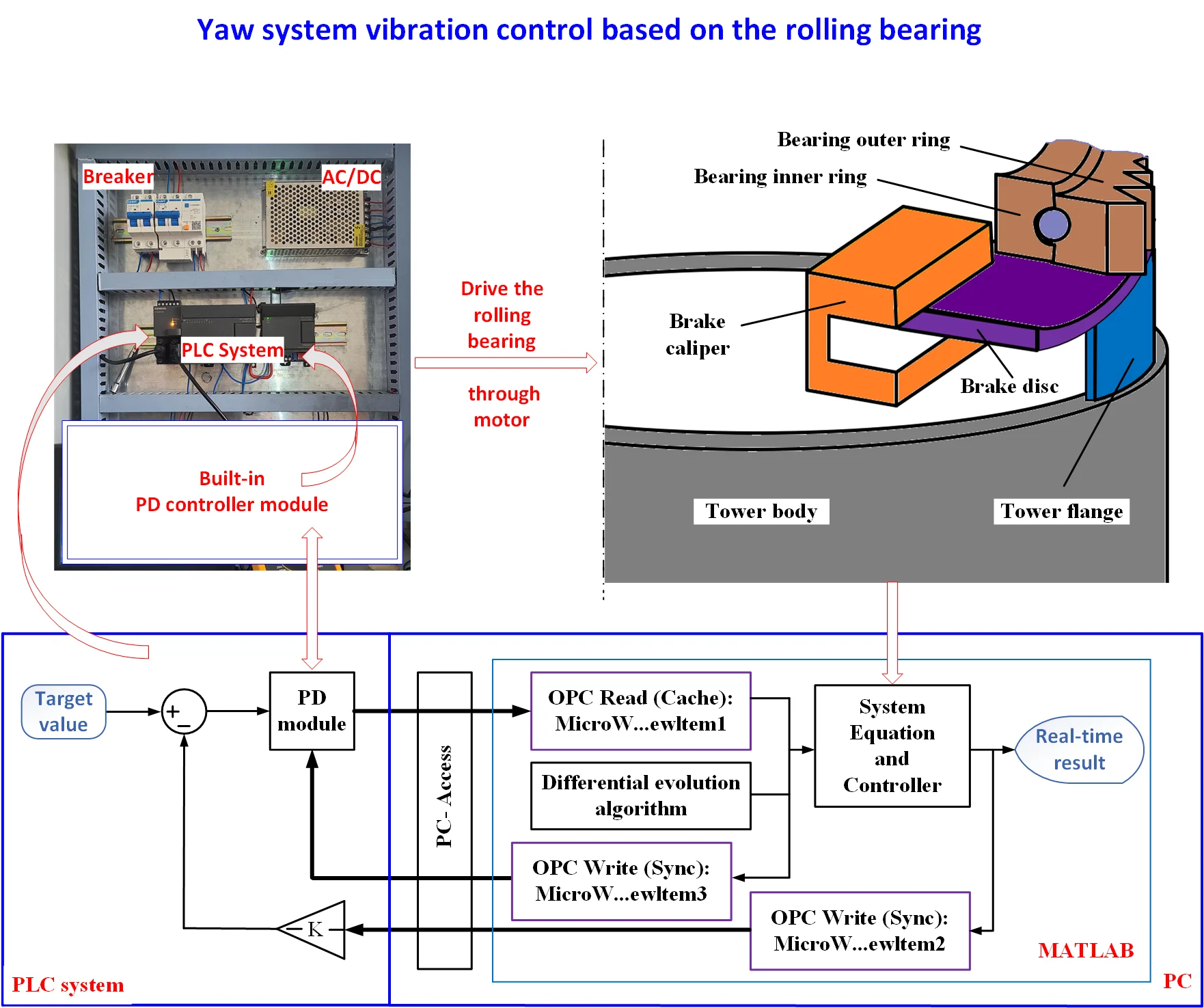
Highlights
- Yaw system vibration control based on the rolling bearing is investigated, with the nonlinear vibration model constructed and integrated to form the governing equations.
- An optimal trajectory control strategy is investigated to suppress the nonlinear system vibration. This strategy uses a differential evolution algorithm to perform an optimal planning along a given ideal path.
- The engineering application effect of the proposed control algorithm is demonstrated based on a type of concise OPC communication technology. This technology directly connects the hardware system of the PLC with the simulation environment of the PC.
1. Introduction
Yaw and pitch motion (YPM) widely occurs in the motion process of many rotary power systems and fluid-driven power equipment. Therefore, the stability of YPM and the stability of its assisted movement have always been a research hotspot. The modeling theories and vibration control methods of various vibration systems are the focus of the research objects. For a large wind turbine (LWT), compared to the pitch motion, the yaw motion is directly related to the behavior of a tower and has a greater impact on the vibration of the entire LWT system. A research report on the yaw motion of an unmanned helicopter system for solving the nonlinear tracking problems was presented in reference [1]. The nonlinear system equation was transformed into a simplified affine model, with a Lyapunov algorithm used for estimating the unknown system parameters. Meanwhile, an adaptive controller based on the Lyapunov algorithm was investigated for the important component of autonomous flight. A novel control mechanism was investigated to generate the yaw control torque of a hovering robot bird by Roshanbin and Preumont [2]. The process of this mechanism generated the yaw torque by modifying the bird wing kinematics while minimizing the influences of the wing on the pitch motion. Stotsky [3] investigated the yaw control and nonlinear speeds of a turbine-driven ship. In this study, the variability of wind speed and direction, as well as the limitations of yaw rate and range, led to the requirement for real-time and rapid response of the turbine control system. The changes in the wind speed and direction were offset by the yaw angle of the turbine system, so that the thrust of the turbine always aligns with the preset direction.
With the scale-up of turbine systems, yaw effects and yaw control, especially for megawatt level LWT systems, are also worth studying in the application of various advanced control methods, such as sliding mode control (SMC), radial basis function neural network (RBFNN) control, model predictive control (MPC), intelligent fuzzy control (IFC), intelligent fractional order proportional-integral-derivative (PID), iterative learning control (ILC), and various wind tunnel test (WTT) control, etc. An adaptive SMC controller based on RBFNN for stable suspension control of a LWT magnetic levitation yaw system was established by Cui et al. [4]. This SMC controller adopts the magnetic levitation drive technology instead of a traditional gear drive technology. It has the advantages of no lubrication, simple structure, and high reliability. A coupling yaw model using a multi-source driving way was proposed by Dai et al. [5]. The proposed model studied different yaw angle control modes using MPC control. In the model, a hydraulic braking system, a transmission system, and an electronic power supply system were jointly established, achieving the coupling of the multi-source multi-channel subsystem for the yaw driving.
Due to the randomness and time-varying nature of the wind direction, it is difficult to accurately predict the target value of yaw angle. The power effect of the yaw control based on the predicted wind direction is limited by the accuracy of the wind direction prediction, resulting in limitation in the improvement of energy capture efficiency of LWTs. To address this issue, a stochastic model [6] based on intelligent scene prediction was proposed to predict the yaw control through MPC. Through the proposed scene-based prediction strategy, the optimized yaw angle was obtained and used to improve energy capture efficiency [6]. In addition, with the emergence of LWT clusters, extensive research has been conducted over the years on the physical characteristics and effectiveness of active yaw processes under various wind conditions based on WTT experiments and wind farm models. For example, Zong and Agel [7] elucidated the influence of turbulence intensity and flow spacing on active control strategies, and conducted in-depth research on the distribution patterns and interrelationships of peak power gain, wind farm scale, and the optimal yaw angle.
The time response analysis of yaw motion system and the stability of controller performance itself are also important aspects of yaw motion system research. This requires the use of intelligent control methods to make the controlled object more stable in the time-domain response and achieve the set motion trajectory more perfectly. At the same time, the entire control plan should not only have the convenience of software development, but also the physical feasibility of hardware implementation, so as to further improve the feasibility of the active control engineering applications [2], [8], [9]. For instance, a robust fractional order PID design method for the yaw motion was proposed, and the fractional order control was achieved using a three-dimensional stability domain analysis method [10]. In addition, based on a nonlinear IFC observer, active rear steering and direct yaw moment coordinated control were adopted, and the stability of the IFC/SMC mode controller was verified using the Lyapunov method, greatly improving the stability control of yaw motion [11]. Meanwhile, a semi-physical simulation platform was developed using finite element analysis integrated with the instrument monitoring platform, characterized by the physical feasibility of hardware implementation. The controller adopted by the platform significantly improves yaw stability.
In fact, the CJ vibration is a type of low-speed (LS) vibration. For the LWT yaw system, a typical LS servo motion system consists of yaw sliding or rolling bearings and a yaw drive structure. Therefore, during the process of the yaw crawling, a frictional self-excited vibration is inevitable, which affects the stability of the yaw system and the accuracy of the yaw motion [12]. In summary, an engineering designer would investigate a kinematic mechanism of the yaw system from the perspectives of friction and lubrication, establish the CJ kinematic model based on the equilibrium position, analyze the motion law of the yaw system and the influencing factors of yaw accuracy, which is bond to have positive engineering significance for the practical application of LWT units.
For the nonlinear controlled objects with periodic repetitive motions, the ILC algorithm [13] has unique advantages in the trajectory tracking and parameter estimation of nonlinear vibrations. Especially, strengthening the ILC algorithm can promote the convergence of the controlled object and accelerate the complex iterative process of smart PID control [14]. On the one hand, the iterative algorithms have good tracking effects on preset values, and on the other hand, they can be combined with PID controllers to limit the output of the controlled object to fluctuate near the target, forcing the output value to show a convergence trend over time [15].
The CJ flutter suppression is an important but rarely studied topic. The vibration suppression can be achieved based on the position of the yaw balance point and a constant yaw angle, which is actually a qualitative analysis method [12]. Based on the joint driving of a lead motor and a slave motor, the nonlinear CJ vibration suppression was achieved by using the ILC algorithm mentioned above. This is a recommended method, but it is based on the research on the yaw system using the sliding bearings that we have addressed in reference [16].
In the present study, the OTC strategy for eliminating the CJ vibration in the yaw motion was studied [17], and the yaw vibration suppression was achieved. An equilibrium position-based yaw kinematic model was deduced to address the amplitude suppression problem of the CJ vibration in the yaw system of megawatt turbines using the rolling bearings instead of the conventional sliding bearings. On this basis, a nonlinear CJ vibration model was established. Based on the differential evolution optimization, the PD controller was adjusted and implemented to achieve the stability control and jitter suppression during the trajectory tracking process. Finaly, a concise OPC technique, i.e., a technique of object linking and embedding for the process control communication, was used and validated to confirm the feasibility of the OTC algorithm execution and the engineering implementation in the controller hardware.
In the present study, the PD controller itself serves as the output torque of the yaw motor and performs error control on the yaw angles. The input voltage of the motor is provided by the frequency converter. Therefore, another feature of this design is to associate the voltage provided by the frequency converter with the driving pressure of the yaw brake (a type of hydraulic brake caliper), achieving dynamic continuous braking.
2. Mechanical structure and mathematical modeling
At present, there are two types of yaw bearings for mainstream wind turbines: rolling bearings and sliding bearings. The yaw system using a rolling bearing adopts a contact ball bearing structure. Due to the small rolling friction coefficient of a rolling bearing, yaw brakes and yaw dampers are usually installed. The yaw system using a sliding bearing does not require the installation of additional LS yaw brakes and dampers due to much larger friction coefficient of the sliding bearing compared to the rolling bearing. Regardless of the bearing structures, discontinuous intermittent motion is prone to occur under low speed and heavy load conditions, resulting in the above-mentioned “crawling vibration” phenomenon. The yaw system using a sliding bearing generates crawling vibration due to poor lubrication between the sliding pad and the gear ring during the yaw process. The unit using a rolling bearing generates crawling vibration due to instability caused by metal material particles attached to the surface of the brake pads. The CJ vibration mentioned above is a special crawling phenomenon based on the yaw balance position, which is more likely to cause damage to the yaw system under extreme working conditions.
2.1. Mechanical structure of the yaw system
Fig. 1(a) shows the engineering diagram of the entire yaw system, including core structures, such as yaw motors, brake calipers, and the rolling bearing, herein, numbers ACs (1-5) are accessory components. The physical structure that causes CJ vibration includes two units. The first unit is the active unit connecting the yaw motor; The second unit is the passive unit which is exactly the load shaking unit.
Fig. 1The mechanical structure of the yaw system
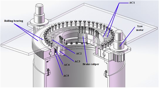
a) The engineering diagram of the entire yaw system
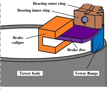
b) The rolling bearing-based system structure
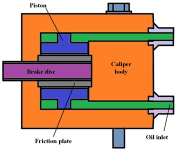
c) Brake caliper
Fig. 1(b) shows a rolling bearing-based yaw system structure. The outer ring of the bearing is driven by two yaw motors through the meshing of the outer ring gear and the motor gears. The outer ring, brake disc, flange, and tower body are fixedly connected as a whole and remain stationary during the motor-driving process. The motor is fixed on the engine base, which is fixedly connected to the bearing inner ring and brake caliper. When the motor gear is driven, the yaw motion of the engine compartment is achieved through the rolling of the inner ring of the bearing.
Fig. 1(c) shows the brake caliper. In conventional design, the brake caliper is only activated during yaw braking, driven by a hydraulic system with constant pressure, and achieves yaw braking through friction with the brake disc. However, in the present study, when the yaw system reaches the equilibrium position, the brake caliper is activated. The hydraulic driving force is related to the output voltage of the frequency converter of the yaw motor, presenting an inverse proportional relationship (the proportional coefficient is calibrated by the practical working conditions), achieving an auxiliary suppression effect on the CJ vibration.
2.2. Mathematical vibration models
Based on a physical structure in reference [12], a physical technique of the CJ vibration in yaw systems based on sliding bearings was explained and solved [18]. In the present study, we used another type of yaw system based on rolling bearings, which is divided into two units as mentioned above. The first unit is the active unit connecting the motors and the loads, which includes the frame and its auxiliary equipment, the engine compartment and its auxiliary equipment, and other accessory connectors. The passive second unit is the load shaking unit, which only includes the part of the engine compartment shaking and its sealing components.
As shown in Fig. 2, the first unit 1 pushes the second unit 2 at an angular velocity , which is exactly the rotary velocity of the yaw motion. and are stiffness coefficient and torsional damping coefficient, respectively. At the equilibrium position of the yaw motion, with the push initiated by the first unit 1, the spring implements the energy storage/release processes, while the second unit 2 implements the acceleration/deceleration processes, thus forming a periodic “crawling vibration” motion, which is exactly the CJ vibration mechanism.
Fig. 2The CJ vibration physical model: 1 – the first unit; 2 – the second unit
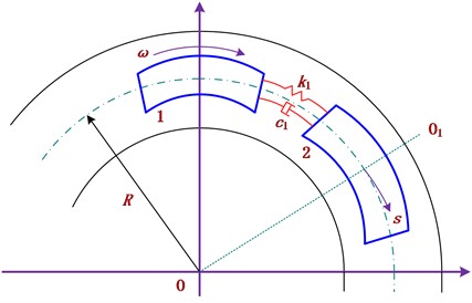
Assuming a distance that the unit 2 moves after time is . Due to the difference between the dynamic friction coefficient and the static friction coefficient, the mathematical differential equation of the motion of follower 2 can be described as:
where is the moment of inertia; is the damping attenuation coefficient, with , herein, . The structural and performance parameters are shows in Table 1. Herein, unlike the yaw systems based on the sliding bearings, the positive torque on the right side of Eq. (1) is omitted due to the small dynamic friction coefficient of the rolling bearings in this study.
Table 1The structural and performance parameters
Items | Values | Items | Values |
Moment of inertia of follower 2, | 330.2 Kg m2 | Damping ratio, | 0.04 |
Radius, | 1.1575 m | Moment of inertia, I | 6603.9 Kg m2 |
Damping ratio, | 0.05 | Change rate of friction moment attenuation, | 0.6 |
Spring stiffness, | 10 N m/rad | Static friction coefficient, | 0.05 |
Spring stiffness, | 3.3×10⁸ N m/rad | Total mass of yaw disk, m | 4929 kg |
The yaw system of a large wind turbine sits on its tower body. It can be equivalent to a disc sitting on a torsion spring with the stiffness and damping . The disk moment of inertia is , the disk mess is , and the radius is . The yaw moment is denoted by , the friction moment is denoted by , and the yaw angle is denoted by . The equilibrium position state is characterized by , representing the “equilibrium point (EP)”, when the yaw moment just overcomes the friction moment under different wind conditions. Therefore, under different wind conditions, the mathematical differential equation based on equilibrium position can be uniformly expressed as:
where is the yaw moment attenuation coefficient; (mg) is the static friction moment; is the change rate of the friction moment attenuation that can be found in Table 1.
From Eq. (2), we can obtain the free vibration equation of viscous damping as:
where ; ; Herein, is the damping ratio of the yaw rotational friction instability. The related structural parameters are shown in Table 1.
A variable replacement method is proposed to solve the differential equations given in Eqs. (1) and (3). In Eq. (1), since the rotary speed of the unit 1 is represented as , while is a composite variable, we can also assume that , then there exist:
Substitute in Eq. (4) into Eq. (1), then rewrite Eq. (1) as:
Substitute in Eq. (3) into Eq. (5), then rewrite Eq. (5) as:
Considering Eqs. (6), (3), and (7) in sequence, assuming the state variable vector is , we can get the governing system equation as:
where , and are 3×3 parameter matrices.
In the present study, we assume that the yaw moment is applied to the right end of the Eq. (3). Based on the EP position, it is exactly the driving torque of the yaw motors on the yaw gear. The governing system Eq. (8) can be rewritten as:
3. PD-based optimal trajectory control
The optimal trajectory can be indirectly obtained by optimizing the deviation from the target trajectory. Assuming the maximum time for the system to reach the steady state is , and considering the law of conservation of energy, the total energy consumed by the system during motion is represented by the work done by non-conservative forces. The objective function selection for the -th variable is:
where , and is a weight value. is the control input signal. , which is the difference between the real-time tracking trajectory and the preset (idea) trajectory.
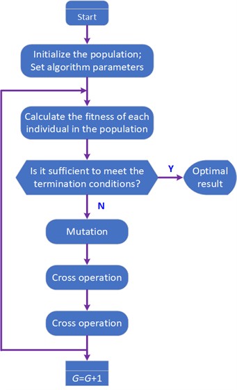
For a 3-variable system, the overall objective function is . The optimal trajectory can be obtained by using the differential evolution algorithm to minimize . The five sets of parameters for the differential evolution algorithm include: maximum iteration number , population size , search space dimension , amplification factor , and crossover factor . By using differential evolution algorithm, a set of optimal biases can be obtained, and the optimal discrete trajectory of the -th variable can be obtained:
In order to obtain continuous optimal trajectories, the cubic spline interpolation method is used in trajectory planning to interpolate discrete trajectories. The boundary conditions for the interpolation of the -th variable are as follows:
The interpolation nodes are:
Using the interpolated continuous function as the -th variable to track the optimal trajectory, the basic operation process of the differential evolution is shown in Fig. 3.
Fig. 3The operational process of the differential evolution
The tracking error is defined as , , and independent PD control is adopted to meet the requirements of position control. The PD controller is described as:
where and are the proportional and derivative parameters of PD controller, which are also optimized and obtained through the differential evolution process. The specific steps are as follows:
– Determine the approximate range of and based on practical experience. Randomly generate an initial population of individuals.
– Decode each individual in the population into corresponding parameter values, and use these parameters to solve the cost function which is the performance indicator based on time integration of absolute error values. To prevent excess control energy, the square term of the control input is added into the cost function: .
– Use the differential evolution algorithm to operate on population and generate the next generation population . Repeat above steps until the parameters converge or reach the predetermined indicator effect.
It should be noted that Eq. (2) is a system equation based on the EP position, which already covers position adjustments under different wind speed conditions. Even if there are special disturbances on this basis, the PD-based optimal trajectory control (PD/OTC) algorithms proposed in this article can make corresponding real-time adjustments and achieve good control effects. This is precisely due to the superiority of the differential evolution algorithm that has the adaptive function to disturbances [19]. And in the early literature [20], the robustness of OTC algorithm has also been validated, testing the optimized PD parameter results through different load disturbances. The results clearly demonstrate that the PD parameters optimized using differential evolution algorithm can better adapt to the frequency changes of the system, reduce the frequency error and response time of the system.
4. Numerical simulation and discussion
The related structural parameters follow the items given in Table 1. During simulation process, we specify the differential evolution algorithm parameters. Let 5, 500, then the sampling time is 0.005. For each variable interpolation point, there is 4. The horizontal axis of the interpolation point is fixed at the 200th, 400th, 600th, and 800th points, and the corresponding vertical axis is set at four random values between the initial and final points. The value of the -th interpolation point of the-th () sample is:
The other algorithm parameters include: 0.3. 50, 0.5, 0.9, and the maximum iteration number is 100. Continuously optimizing the ordinate values of four interpolation points using the differential evolution method, the satisfactory optimization indicators and optimization times can be achieved. In addition, the optimized PD parameters are:
Based on two different target yaw angles, 0.02 rad and 1 rad, calculated from their respective equilibrium positions, Fig. 4 shows the uncontrolled CJ vibration (i.e., the jitter) displacements () and yaw angle fluctuations (), respectively. The fluctuation trend of CJ vibration shows consistency in each situation, that is, low-speed jumps with an amplitude of ±0.05 m. This is more likely to cause damage to the yaw system when the yaw crawling occurs. From the perspective of yaw vibration, in any case, when reaching the target position, there still exists a gradually decaying high-frequency (micro-amplitude) vibration, which is also harmful to the yaw system.
Fig. 4The uncontrolled CJ displacements
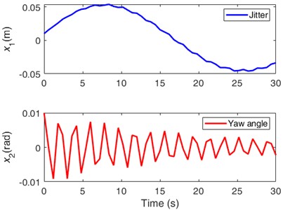
a) The target yaw angle is 0.002 rad
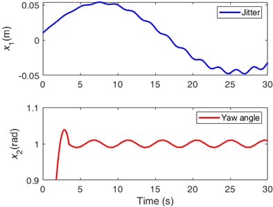
b) The target yaw angle is 1 rad
4.1. Vibration control
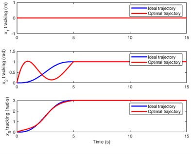
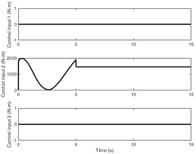
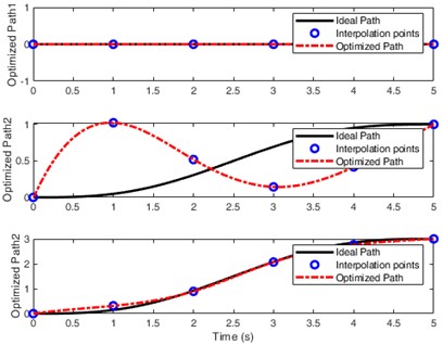
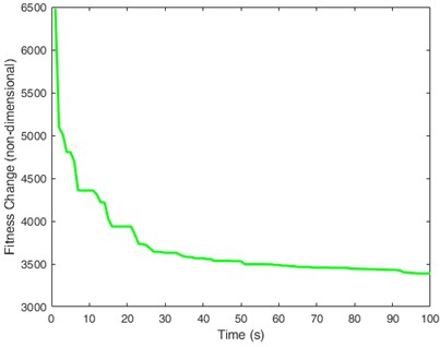
The system equation Eq. (9) is an underactuated system with fewer independent control variables than the number of degrees of freedom. It is superior to fully actuated systems in terms of energy savings, cost reduction, and enhanced flexibility. Given the target value for the controlled objects in Fig. 4(b), Fig. 5 illustrates the optimization process and optimal trajectories (a), inputs for the underactuated control signals (b), the optimal paths and interpolation points (c), and the changes in fitness (d). Displacement tracking has been achieved within 5 s, and the optimal trajectory and ideal trajectory tend to be completely consistent in Fig. 5(a). Due to being an underactuated system, Fig. 5(b) only shows the control input for yaw angle, which is exactly the driving torque of the driving motor. Fig. 5(c) shows four differential interpolation points and their paths, achieving a perfect control effect. The fitness changes in Fig. 5(d) gradually stabilize over time, demonstrating good adaptability.
In Fig. 5, displacement (the CJ vibration) in (a), the control input for in (b), and the optimized path for in (c) all have zero fluctuations, demonstrating a perfect control effect, which is also a characteristic of underactuated control.
To highlight the superiority of the underactuated control, Fig.6 illustrates the vibration control of fully actuated system based on the PD/OTC algorithms. Compared with the results in Fig. 5, Fig. 6 shows the “zero value” fluctuation effect of displacement , which also achieves a perfect control effect. However, all three control input signals are present in Fig. 6(b), which means more energy consumption and more complex hardware systems. For example, how to input the right-hand side of Eq. (6) for the displacement will introduce complex control methods and system hardware, increasing the difficulty of engineering applications.
In addition, from the numerical changes in fitness, the amplitude in Fig. 5 is smaller, which means that the control process is smoother and the energy consumption is more stable. However, whether for underactuated or fully driven systems, the PD/OTC method can achieve perfect control, complete disappearance of jitter, fast tracking, and stable yaw angle, further confirming the robustness of the proposed method.
Given the superiority of the controlled underactuated system, subsequent verifications will be based on the underactuated system.
Fig. 5The illustrations of the underactuated system
a) The optimization process and optimal trajectories
b) Inputs for the underactuated control signals
c) The optimal paths and interpolation points
d) The changes in fitness
Fig. 6The illustrations of the fully actuated system
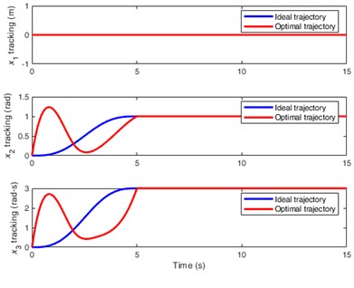
a) The optimization process and optimal trajectories
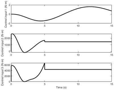
b) Inputs for the fully actuated control signals
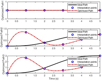
c) The optimal paths and interpolation points
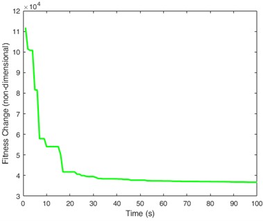
d) The changes in fitness
4.2. Robustness of the PD/OTC algorithms
Due to the complete disappearance of jitter, the robustness verification of PD/OTC has focused on the control effect of yaw angle. To further verify the robustness of PD/OTC in underactuated control, Fig. 7 shows the control effect under different target yaw angles, with 0.5, 0.8, 1.2, 1.5 rad, respectively.
From the perspective of tracking, satisfactory yaw angle control can be achieved in all four cases, and it can remain stable at the given value within 5 seconds, which is completely consistent with the control effect in Fig. 5(a). In all four cases, the control input 2 can also stabilize within 5 seconds, which is completely consistent with Fig. 5(b). The optimal path can also be optimized based on 4-point interpolation. The fitness changes can also quickly converge and stabilize, and small changes in fitness mean lower energy consumption and control costs.
It should be emphasized that we do not need to pay attention to the changes in , as it is a variable that fluctuates over time. Even if is divergent and unstable, as long as and can stabilize, it indicates that the control method used is feasible. In fact, in all four cases can be stable and converge as the fluctuation shown in Fig. 5(a), further verifying the robustness of the PD/OTC algorithms.
5. Engineering application based on the PD/OTC algorithms
At present, the control system of wind turbines mostly uses the CPU module of Programmable Logic Controller (PLC) as the core controller. Therefore, the application of theoretical control algorithms in practical controller hardware has always been and will be an important topic in the future. This is a necessary step for engineering applications, as not all intelligent control algorithms can be tested through practical testing in hardware.
Fig. 7The control effect under different target yaw angles, with θd=x2d= 0.5, 0.8, 1.2, 1.5 rad, respectively
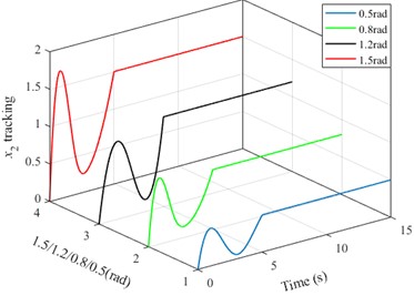
a) The yaw angles tracking
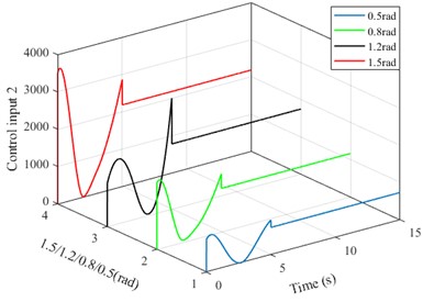
b) Motor input torques
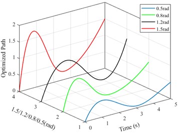
c) The optimized paths
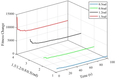
d) The fitness changes
The PD/OTC algorithms in this article can actually be divided into two parts: the OTC algorithm based on the differential evolution, and the PD parameter tuning and PD control implementation based on the differential evolution. Due to the limitations of CPU module performance, neither of these algorithms can be directly implemented in PLC through programming. Therefore, we have taken the following measures:
– The OTC algorithm based on differential evolution is usually run in MATLAB.
– The first run of PD parameter tuning based on differential evolution was implemented in MATLAB. The optimal PD parameter value obtained is fixed and written to the CPU. In subsequent PD controls, there is no need to adjust the parameters again.
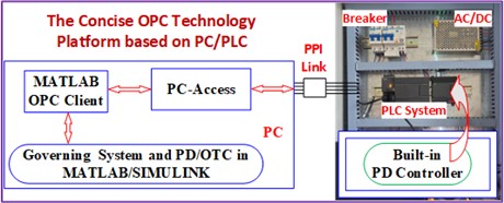
– The PD control is fully implemented within CPU224XP and executed using the built-in PD program module of the PLC CPU.
– The communication between PLC CPU and MATLAB, as well as the execution of the above algorithms, are achieved through the concise OPC technology mentioned in reference [21].
Still taking the controlled objects in Fig. 4(b) as an example, we further investigate the engineering application of the algorithms in CPU implementation. Fig. 8(a) shows the OPC communication planning and the PLC system experimental setup.
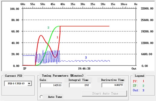
The PD parameters are adjusted and confirmed by the differential evolution as , (the corresponding derivative time is 0.00175 minute). Open the PID tuning control panel in the programming software of PLC, then fix the PD parameters obtained through tuning and write them into the panel. Fig. 8(b) illustrates the present value (PV) of yaw angle (red) tracking the given value of yaw angle (i.e. the set value, SP, is marked in green), as well as the output of PD controller (blue). Compared with Fig. 5(a), the real-time PV value of yaw angle shows a fluctuation pattern and trend that is very close to that in Fig. 5(a). Of course, there are still subtle differences in the fluctuation curve, as this is caused by the sampling step size of the physical hardware. However, the dynamic fluctuation in the panel is sufficient to demonstrate the feasibility of the proposed PD/OTC algorithms in engineering applications.
It should be emphasized again that PD parameter adjustment is only performed once and may take a long time. After the adjustment is completed, the parameter values are fixed and directly applied to the subsequent hardware execution, which can accelerate the real-time control process.
Fig. 8The experiment setup
a) The concise OPC technique platform based on PC/PLC
b) The real-time tuning of PD parameters and output of yaw angles
Special emphasis should be placed on the OPC communication link. To ensure consistency of the MATLAB simulation and the practical PLC implementation, Fig. 9 demonstrates the implementation processes of the OPC communication link. The PLC CPU and MATLAB environment in PC can communicate with each other through OPC servers built by PC- Access software (PAS). The items in PAS occupy specific addresses corresponding to the PLC memory area. The OPC read module can read signals from PLC CPU (reading cache data from the CPU due to data lag caused by CPU scanning principle) by connecting the corresponding items built in the PAS. The OPC write module in MATLAB environment can write signals to PLC CPU also by connecting the corresponding items built in the PAS. The “write” operation is executed synchronously. On the one hand, it directly sends the execution results of OTC control in the simulation environment to the PLC CPU, and on the other hand, it directly writes the two optimal PD parameters formed by differential evolution into the built-in PID ladder program module ‘within’ the CPU.
In addition, in Fig. 9, the unit “-K-” is a time-domain step expansion unit that uniformly expands the step size in the simulation environment to a step size suitable for the PLC CPU scanning cycle, in order to accelerate real-time communication speed and ensure a certain level of accuracy.
Fig. 9The implementation processes of the OPC communication link

It should be noted that the proposed PD/OTC controller is not only suitable for low-speed low-frequency control in the present study, but also for high-speed high-frequency vibration control. However, it is well known that vibration suppression controllers may lose stability under certain high-frequency vibration conditions. Therefore, in order to achieve the control objective, it is only necessary to replace the optimal PD with the optimal fractional order PD, and the mathematical expression of its controller in Laplace transform complex frequency -domain is as follows:
where is a fractional order regulatory factor. Due to the presence of the factor and the high-precision performance of OTC, it is easy to perform fast differential operations and speed adjustments, which can directly accelerate the execution speed and fully adapt to the high-frequency vibration control of the controlled objects. This can enable the system to converge and stabilize at a certain value after a period of time.
6. Conclusions
In this study, the yaw vibration and CJ vibration of the rolling bearing-based yaw system are investigated, and the vibration control is implemented based on the PD/OTC algorithms. Some conclusions can be drawn from the research results:
1) Both OTC control and PD regulation are based on the differential evolution algorithm. In OTC control, differential evolution is always required, while in PD regulation, the differential evolution algorithm only needs to be executed once. The determination of differential evolution parameter values depends on the experience of numerical simulation and engineering applications, but for a specific controlled object, once established, there is no need to make further changes.
2) The concise OPC technology platform provides support for the engineering application of the PD/OTC algorithms. In fact, for many intelligent control algorithms, as long as they are combined with the PD control, the platform can be applied, which also provides a reference for the control engineering of wind power generation systems.
3) The novelty of this study can be summarized as follows. Firstly, this article studies and solves a rarely discussed CJ problem in yaw systems based on rolling bearings, and proposes a PD/OTC control strategy based on differential evolution; Secondly, the follow-up lubrication of hydraulic brake calipers mentioned at the beginning of this article is necessary. Its working principle should be combined with PD/OTC method to meet very small rolling friction conditions, so that the positive pressure torque effect can be ignored in Eqs. (1-2). Only in this way can the modeling and control in this article have engineering significance; Thirdly, the concise OPC communication technology can greatly accelerate the joint operation between intelligent control algorithms and PID algorithms (in PLC hardware systems), providing a beneficial method for high-precision PID control in similar engineering projects.
References
-
T. Q. Le, Y. C. Lai, S. G. Voutsinas, and C. L. Yeh, “Adaptive tracking control based on neural approximation for the yaw motion of a small-scale unmanned helicopter,” International Journal of Advanced Robotic Systems, Vol. 16, No. 1, pp. 21–32, 2019, https://doi.org/10.1177/172988141982
-
A. Roshanbin and A. Preumont, “Yaw control torque generation for a hovering robotic hummingbird,” International Journal of Advanced Robotic Systems, Vol. 16, No. 1, Jan. 2019, https://doi.org/10.1177/1729881418823968
-
A. Stotsky, “Nonlinear speed and yaw control for wind turbine powered vessels,” Proceedings of the Institution of Mechanical Engineers, Part I: Journal of Systems and Control Engineering, Vol. 230, No. 3, pp. 255–265, Jan. 2016, https://doi.org/10.1177/0959651815623709
-
G. Cui, B. Cai, B. Su, and X. Chu, “Radial basis function neural network-based adaptive sliding mode suspension control for maglev yaw system of wind turbines,” Proceedings of the Institution of Mechanical Engineers, Part I: Journal of Systems and Control Engineering, Vol. 236, No. 1, pp. 66–75, Jun. 2021, https://doi.org/10.1177/09596518211022068
-
J. Dai, T. He, M. Li, and X. Long, “Performance study of multi-source driving yaw system for aiding yaw control of wind turbines,” Renewable Energy, Vol. 163, pp. 154–171, Jan. 2021, https://doi.org/10.1016/j.renene.2020.08.065
-
D. Song et al., “Energy capture efficiency enhancement of wind turbines via stochastic model predictive yaw control based on intelligent scenarios generation,” Applied Energy, Vol. 312, No. 15, p. 118773, Apr. 2022, https://doi.org/10.1016/j.apenergy.2022.118773
-
H. Zong and F. Porté-Agel, “Experimental investigation and analytical modelling of active yaw control for wind farm power optimization,” Renewable Energy, Vol. 170, pp. 1228–1244, Jun. 2021, https://doi.org/10.1016/j.renene.2021.02.059
-
S. Krim and M. F. Mimouni, “Design and Xilinx Virtex-field-programmable gate array for hardware in the loop of sensorless second-order sliding mode control and model reference adaptive system-sliding mode observer for direct torque control of induction motor drive,” Proceedings of the Institution of Mechanical Engineers, Part I: Journal of Systems and Control Engineering, Vol. 237, No. 5, pp. 839–869, Dec. 2022, https://doi.org/10.1177/09596518221138987
-
Y. Zhang, Z. Wang, Y. Wang, C. Zhang, and B. Zhao, “Research on automobile four-wheel steering control system based on yaw angular velocity and centroid cornering angle,” Measurement and Control, Vol. 55, No. 1-2, pp. 49–61, Dec. 2021, https://doi.org/10.1177/00202940211035404
-
L. Liu, L. Zhang, G. Pan, and S. Zhang, “Robust yaw control of autonomous underwater vehicle based on fractional-order PID controller,” Ocean Engineering, Vol. 257, p. 111493, Aug. 2022, https://doi.org/10.1016/j.oceaneng.2022.111493
-
C. Sun, Z. Xu, S. Deng, and B. Tong, “Integration sliding mode control for vehicle yaw and rollover stability based on nonlinear observation,” Transactions of the Institute of Measurement and Control, Vol. 44, No. 15, pp. 3039–3056, Jun. 2022, https://doi.org/10.1177/01423312221099414
-
P. Zhao, S. C. Gao, et al., Dynamics of Large Wind Turbine. Beijing, China: Science Press, 2018.
-
J. K. Liu, Robot Control System Design and MATLAB Simulation. The Basic Design Method. Beijing, China: Tsinghua University Publishing Company, 2017.
-
I. Zaitceva and B. Andrievsky, “Methods of intelligent control in mechatronics and robotic engineering: a survey,” Electronics, Vol. 11, No. 15, p. 2443, Aug. 2022, https://doi.org/10.3390/electronics11152443
-
L. Feng et al., “Iterative learning based intermittent fault estimation for a class of linear uncertain repeated systems,” Acta Automatica Sinica, Vol. 46, No. 2, pp. 307–319, 2020, https://doi.org/10.16383/j.aas.2018.c170252
-
T. Liu and Z. Nie, “PD-based iterative learning control for the nonlinear low-speed-jitter vibration of a wind turbine in yaw motion,” Applied Sciences, Vol. 14, No. 5, p. 1750, Feb. 2024, https://doi.org/10.3390/app14051750
-
J. K. Liu, Robot Control System Design and MATLAB Simulation. The Advanced Design Method. China: Tsinghua University Publishing Company, 2023.
-
Z. Y. Wang, “Research on tower detection scheme and yaw system jitter-vibration control of large wind turbine,” Shandong University of Science and Technology, Qingdao, China, 2023.
-
T. Wang, K. Wu, T. Du, and X. Cheng, “Adaptive dynamic disturbance strategy for differential evolution algorithm,” Applied Sciences, Vol. 10, No. 6, p. 1972, Mar. 2020, https://doi.org/https://doi.org/10.3390/app10061972
-
C. F. Sun, “Differential Evolution and its application on the optimal scheduling of electrical power system,” Huazhong University of Science and Technology, Wuhan, China, 2010.
-
T. Liu, “Vibration control and trajectory tracking for nonlinear aeroelastic system based on adaptive iterative learning control,” Noise and Vibration Worldwide, Vol. 53, No. 7-8, pp. 390–403, Jul. 2022, https://doi.org/10.1177/09574565221114659
About this article
This work was supported by the Natural Science Foundation of Shandong Provincial of China (No. ZR2022ME093).
The datasets generated during and/or analyzed during the current study are available from the corresponding author on reasonable request.
Tingrui Liu conceived the original idea and wrote the manuscript. Qinghu Cui finished the extensive editing of English language and style. Dan Xu and Tingriu Liu jointly supervised the study.
The authors declare that they have no conflict of interest.
