Abstract
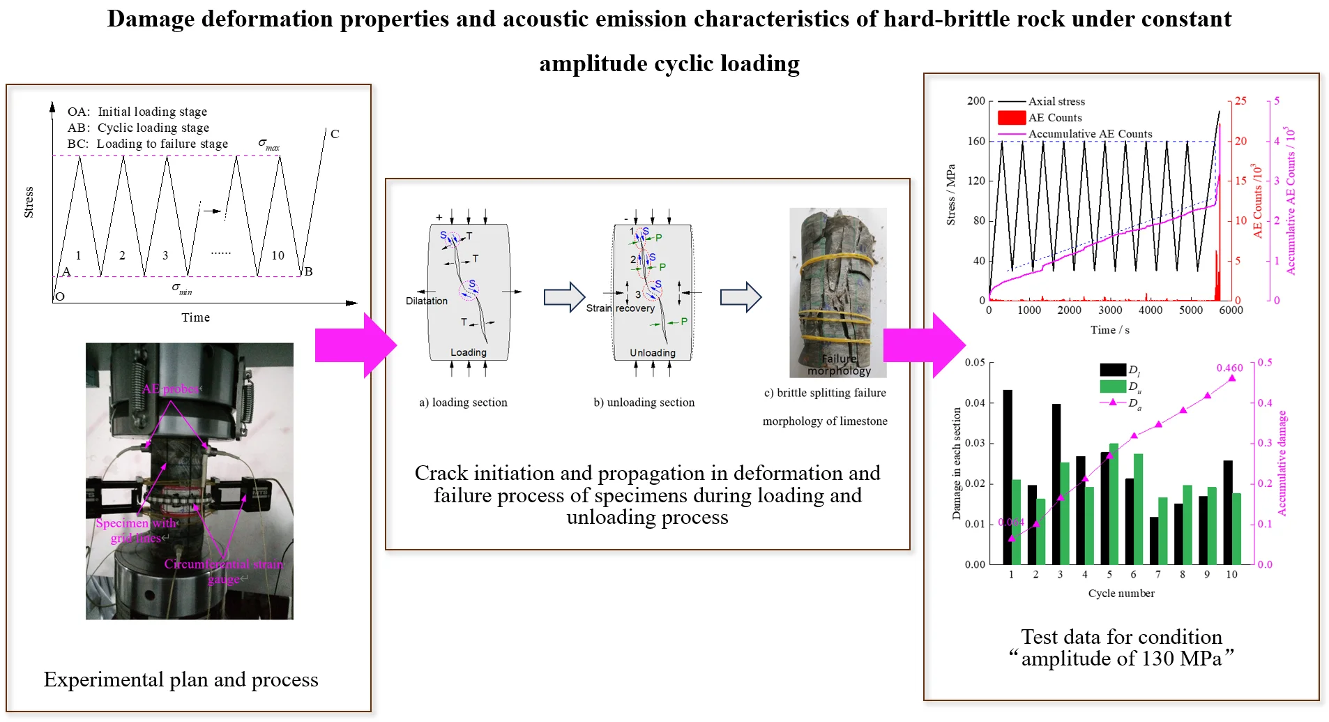
In order to study the deformation and damage characteristics of the limestone specimens with high strength and brittleness under constant amplitude cyclic loading, the deformation and the acoustic emission (AE) characteristics were analysed, and the relationship between them was sought. The damage variables under different amplitude cyclic loading were defined by AE counts. The results showed that the radial deformation of the limestone specimens was more sensitive and unstable than the axial deformation. The concept of apparent residual strain was proposed to describe the specimen deformation characteristics, and it resulted that the radial apparent residual strain produced at higher stress state would recover at lower stress state. The limestone specimens showed obvious Kaiser effect and Felicity effect under cyclic loading. When the upper limit of the cyclic loading was close to the peak stress of the specimen, the AE counts generated in unloading sections were almost the same as that in the loading sections. The damage was increased as the amplitude and the stress level increased and the unloading process at higher stress level would also lead to the aggravation of damages. Specimens would absorb more energy under cyclic loading than under uniaxial loading. Reasonable driving parameters should be controlled in underground excavation practice, to ensure that the stress level of surrounding rock mass in a periodic stress state is located before peak stress and such that to limit the occurrence of rock burst to a certain extent.
Highlights
- Determine the deformation and damage characteristics of high-strength brittle limestone specimens under constant amplitude cyclic loading through strain and acoustic emission characteristics.
- The concept of apparent residual strain was proposed to describe the deformation characteristics of the specimen, and the results showed that the radial apparent residual strain generated at higher stress states would recover at lower stress states.
- Limestone samples exhibit significant Caesar effect and Felicity effect under cyclic loading.
- Reasonable driving parameters should be controlled in underground excavation practice, to ensure that the stress level of surrounding rock mass in a periodic stress state is located before peak stress and such that to limit the occurrence of rock burst to a certain extent.
1. Introduction
In geotechnical engineering constructions, the rock mass is often subjected to periodic loading [1]. For example, in underground mining, the stress of the rock mass near the working face is greater than that of the original rock stress [2], as the working face moves forward and the roof collapses, the stress of the rock mass decreases [3]. Besides, the excavation of adjacent roadways or chambers will cause periodical stress on the rock mass. Another typical example is the rock mass of dam foundation, which is subjected to periodic load during reservoir water storage and discharge. The mechanical properties of rock under periodic loading are closely related to the long-term stability of rock mass engineering.
Cyclic loading tests are effective means to quantitatively measure the rock deformation and damage evolution and to derive parameters for the rock constitutive models [4, 5]. At present, the loading modes of cyclic loading test for rock materials mainly include three types, namely the constant cyclic loading [6-8], the incremental stress level cyclic loading [5, 9, 10] and other loading modes that are slightly modified versions of the former two cyclic modes [11, 12]. Specimen fatigue strength under cyclic loading is generally lower than that under uniaxial strength [13], and with the increase of loading rate, the fatigue strength increases gradually [14, 15]. Cyclic loading tests on coal [7] and rock [16] showed that the hysteresis loops in axial stress-strain curves move to the right constantly, and the sparse-dense-sparse change which indicate that each cycle produced a certain unrecoverable strain which led to an inverted “S” shape of the axial strain-cycle number curve of the specimen. Guo et al. [17] divided the curves into three stages, including the initial deformation, the constant-velocity deformation and the accelerate deformation, whereby the accumulation strain of the three stages leads to specimen damage. Momeni et al. [18] found that the residual axial strain and the lateral strain of Alvand monzogranitic rock specimen decrease with the increasing cyclic loading amplitude. Mo et al. [19] divided into four stages according to the evolutionary characteristics of the crack and stress thresholds. Eberhardt et al. [20] suggested that different failure modes would occur if the cyclic loading exceeded the crack damage stress threshold.
The above studies suggested that the mechanical properties and the deformation characteristics of rock specimens are affected by the cyclic loading parameters. Recently, with the increasing depth of underground engineering, a series of dynamic disasters such as rock burst occur frequently [21, 22]. Studies have shown that rock mass causing dynamic disasters often exhibited strong hardness and brittleness [23, 24], and different kinds of rock specimens would have different responses to cyclic loading [25]. Therefore, conducting such cyclic loading experimental researches on rock specimens with greater strength and brittleness is of great relevance. It is helpful to reflect the real deformation and failure characteristics of hard rock mass with rock burst tendency in the excavation process.
Physical phenomena such as electromagnetic radiation [26], infrared radiation [27] and acoustic emission [28] are often associated with the damage and destruction of rock materials, while AE activity can reveal energy conversion features and estimate the rock stability during its deformation and failure [29, 30]. Considering the importance of the prediction of rock failure, acoustic emission technology was adopted in this cyclic loading tests on limestone specimens under three different amplitudes to explore the AE characteristics and the damage rules during the failure process, which may play an important role in the application of rock-burst prevention and rock engineering design.
2. Experimental scheme of the uniaxial constant amplitude cyclic loading compression
2.1. Specimens and apparatus
The rock samples used in this test were extracted from a heading surface of a roadway in Gubei Mine, Huainan. The cores were processed into Φ50×100 mm standard samples in the laboratory, as shown in Fig. 1(a). The average longitudinal wave velocity and the density of specimens were 5.03×10³ m/s and 2.73×10³ kg/m3, respectively. Gridlines were drawn on the surface of the samples in advance so that the acoustic emission probes could be accurately fixed.
The tests were completed in an MTS 816 rock mechanics test system. The axial load was measured by the load weight installed on the test system, and the axial displacement was measured by the axial displacement extensometer matching with the testing machine. The radial displacement was measured by the circumferential extensometer installed on the specimens. The PCI-2 acoustic emission test and the analysis system used in this test were produced by a US company of physical acoustics. Six channels were used to collect the data in the test process, and each channel corresponded to a separate pre-amplifier and a sensor with a threshold of 40 dB. The acoustic emission probes were coupled to a specimen surface using vaseline, as shown in Fig. 1(b).
Fig. 1Cyclic loading test with diffesrent amplitudes
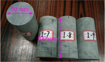
a) Limestone specimens with high strength and brittleness
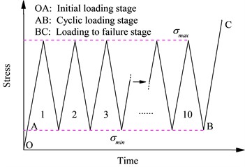
c) Sketch of the cyclic loading path
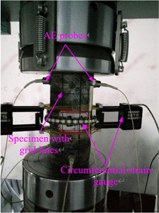
b) AE sensor array and circumferential strain gauge installation
2.2. Testing methodology
Proper cyclic loading amplitudes should be set to explore the response of specimen under cyclic loading with different stress levels, especially the deformation and failure characteristics nearing the ultimate loading. Firstly, the uniaxial compression tests were conducted to obtain the average specimen strength, which was 161.3 MPa. Hence, the maximum values of the three amplitude cyclic loading were set to 70 MPa, 115 MPa and 160 MPa, respectively. All the minimum of cyclic loading were set to 30 MPa to limit the influence of the initial compaction section on the analysis of the experimental results. Therefore, the stress level (the ratio of maximum cyclic stress to static strength) was theoretically 0.43, 0.71 and 0.99, respectively. More than three specimens were selected for each amplitude test. The cycle number in each specimen was set to 10. After completion of the 10 cycles loading and unloading, the specimens were loaded at the same loading rate until failure. The loading and unloading rates were 1 kN/s, and the specific loading mode is shown in Fig. 1(c).
3. Stress and strain characteristics of limestone specimens
3.1. Stress and strain characteristics under uniaxial loading
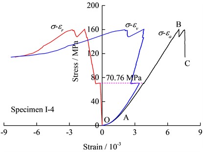
The specimen stress-strain curve under uniaxial loading is shown in Fig. 2. In general, the stress-axial strain curve could be divided into three stages, namely the micropore fracture compaction section (OA), the linear elastic section (AB) and the post-peak failure stage (BC). The elastic stage of the limestone specimens in this test was wide, and the failure stage was not obvious compared to other rocks [25]. The specimens almost directly failed in the elastic section, only a local stress drop phenomenon occurred at point B. The failure process of the limestone specimen was more abrupt whereby a phenomenon of "burst" was observed, causing broken pieces to be dispersed at a long distance, thereby rendering difficult the depiction of the post-peak failure stage of stress-axial strain curve. When the axial loading on the specimen was 70.76 MPa, the radial strain suddenly increased, and the subsequent radial strain growth rate became larger, however the axial strain was not obvious, indicating that the radial deformation process was not stable. The stress-volumetric strain curves suggest that the transformation from the volume compression stage to the expansion stage of limestone is more sudden than for other rocks [18, 19].
Fig. 2Stress-strain curve of limestone specimen Ⅰ-4 under uniaxial loading
3.2. Stress and strain characteristics under cyclic loading
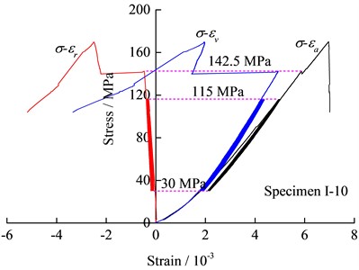
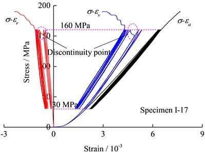
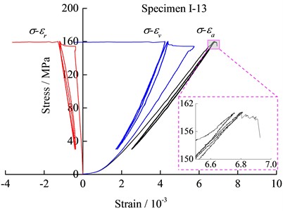
The stress-strain curves of the specimens under cyclic loading with different amplitudes are shown in Fig. 3. The data show that the hysteresis loops in the axial stress-strain curves are closer than that of other rock specimens such as sandstone [31] or rock salt [17]. As shown in Figs. 3(a) and 3(b), there is no abrupt change in strain or stress on the stress-axial or radial strain curves for cyclic loading with amplitudes of 40 MPa and 85 MPa, respectively. In particular, for specimen I-6 with an amplitude of 40 MPa, there is no abrupt change in stress or strain across the stress-strain curve. The axial and radial strains of the specimen Ⅰ-10 dropped at a stress of 142.5 MPa, and the radial strain was greater. The hysteretic loop in the stress-radial strain curve with an amplitude of 130 MPa was sparser than amplitudes of 40 MPa and 85 MPa, and a sudden increase occurred in the radial strain when the axial stress was nearing the peak value of the cyclic loading in the third cycle. Besides, the volumetric rock deformation exhibited an obvious slow expansion stage when the specimen was close to failure, as shown in Fig. 3(c).
Fig. 3Stress-strain curves of specimens under cyclic loads of different amplitudes
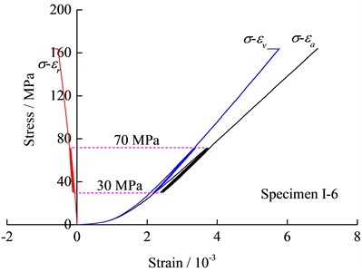
a) 40 MPa amplitude
b) 85 MPa amplitude
c) 130 MPa amplitude
d) 130 MPa amplitude and the stress level is nearing 1
The peak stress of the specimen Ⅰ-17 was 190.38 MPa and was higher than the average strength because of the discreteness of the rock specimen, but the stress level was 0.84 and was still larger than the other two amplitudes. The strengths of parts of the specimens are lower than the maximum of the cyclic loading under an amplitude of 130 MPa and failed to implement the cyclic loading. Fortunately, the strength of the specimen I-13 seemed to be very close to the maximum of cyclic loading and the failure occurred near the third cycle peak stress, as shown in Fig. 3(d). The radial strain increased abruptly at the initial loading stage when the axial stress was about to reach the maximum of the cyclic loading. Nearing the maximum of the third cyclic loading, instability failure occurred after a short yield stage. Similarly to the other specimens, no sudden large change occurred in the stress-axial strain curve.
The above analysis of the stress-strain curves of the limestone specimens under uniaxial and cyclic loading shows that a strong elasticity was observed in the axial deformation regardless of the stress level cyclic loading. The influence of the stress level of cyclic loading on radial strain was significantly greater than that of axial strain, and the radial strain was prone to sudden increase. Although the radial deformation was significant under high-stress amplitude loading, it does not imply that Poisson’s effect was larger in a strict sense, because the slope of the stress-axial strain curve exhibited little change in the loading section (except the sudden change parts). The heterogeneity of the radial deformation showed that the appearance of the plastic regions or the micro-fracture surfaces in the specimens were local and mainly axial, while the majority kept integrity, maintaining the overall stiffness and stability of the specimen.
3.3. Axial and radial apparent residual strain under cyclic loading
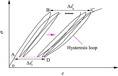
The rock specimen was heterogeneous material that would produce residual deformation after removing the loading on it. All of the three amplitudes cyclic loading resulted in the radial and axial residual deformation after 10 cycles loading and unloading. However, the minimum of cyclic loading in this test was 30 MPa (incomplete unloading), and whether the peak or valley strain difference between hysteresis loops was a residual strain (unrecoverable) remained to be investigated. Therefore, the apparent residual strain was introduced to indicate the deviation in the strain between the hysteresis loops at peak or valley stresses of the cyclic loading, as shown in Fig. 4, where ε includes the radial strain and axial strain, while Δεtu and Δεtl are the total apparent residual strains at the upper limit and lower limit of cyclic loading, respectively.
Fig. 4Schematic diagram of apparent residual strain under cyclic loading
The radial and axial accumulative apparent strains under different stress levels are shown in Table 1, where Δεtua and Δεtur are the axial and radial total apparent residual strain at the upper limit of cyclic loading, respectively (loading section in the initial cycle and unloading section in the last cycle are not included), while Δεtla and Δεtlr are the axial and radial accumulative apparent residual strain at the lower limit of the cyclic loading, respectively. The variation of the axial accumulative apparent residual strain appears to be lesser than the radial apparent residual strain, which means that the cyclic loading had a greater effect on the radial strain than axial strain. Δεtua is larger than Δεtur under 0.43 and 0.71 stress level, but smaller under 0.84 stress level, which indicates that the apparent radial residual strain at the upper limit of the cyclic loading was partially recovered when the loading decreased and it was not strictly a residual radial strain which was unrecoverable. Similar results can be derived in the deformation process of the specimen Ⅰ-13, where the applied stress level exceeded 0.84.
Table 1Accumulative apparent residual strains at upper and lower limit of cyclic loading with different amplitudes
Stress level / MPa | Δεtua / 10-4 | Δεtur / 10-4 | Δεtla / 10-4 | Δεtlr / 10-4 |
0.43 | 0.88 | 0.38 | 2.14 | 0.61 |
0.71 | 0.85 | 1.01 | 3.47 | 1.67 |
0.84 | 1.67 | 6.16 | 3.66 | 4.47 |
The above analysis suggests that the radial strain during the loading process from low stress to high stress could be expressed by the following equation:
where Δεr is the difference of the radial strains between high and low stresses, εre is the elastic strain, εrp is the plastic strain and Δεrr is the recoverable radial apparent residual strain.
4. Acoustic emission characteristics of limestone specimens during deformation and failure process
4.1. Acoustic emission characteristics under uniaxial loading
The characteristic parameters of the acoustic emission include Hit, Event, Counts, Energy, Duration and Rise time, where the AE Counts represents the number of oscillations of the signal above the threshold and can be used to evaluate the activities of the acoustic emission. Therefore, the AE Counts during the deformation and the failure process of the specimen was mainly analysed in this study.
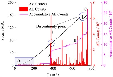
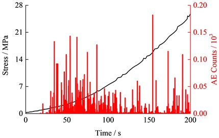
As shown in Fig. 5(a), the accumulative AE Counts curve under uniaxial loading could be divided into three stages, including the gentle development stage (OA), the constant-velocity growth stage (AB) and the accelerated growth stage (BC). The compaction process of the micropores and micro-fissures under the lower loading would lead to the generation of a certain amount of elastic wave (Fig. 5(b)). The AE Counts increases suddenly at point A, which may be due to the occurrence of local axial failure surface according to the radial deformation characteristics in Fig. 2. The accumulative AE Counts exhibited a noticeable stepwise increase after point B, which indicates that unstable deformation state occurred in this transient stage. The accumulative elastic energy released with the complete instability and the failure of the specimen, which resulted in a large amount of elastic waves and the accumulative AE Counts subsequently increased to the maximum.
Fig. 5Variation of axial stress, AE counts and accumulative AE counts with time under uniaxial loading
a) Chart of changes throughout the time period
b) Plot of changes in time period from 0 to 200s
4.2. Acoustic emission characteristics under uniaxial loading
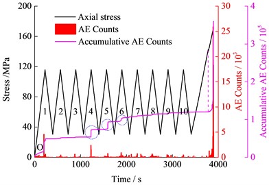
Fig. 6 shows the various characteristics of the AE Counts with time under three amplitudes cyclic loading. When the amplitude was 40 MPa (Fig. 6(a)), a small amount of AE counts were produced in the initial cyclic loading section (OP), while AE phenomenon rarely occurred in the next cyclic loading and unloading stage (PQ). When the stress on the specimen exceeded the upper limit of cyclic loading, AE Counts began to increase obviously (QR), indicating the presence of a Kaiser effect in the rock specimens [32].
Fig. 6(b) shows that when the cyclic loading amplitude was 85 MPa, the AE Counts in the initial cycle loading section were almost ten times of that when the amplitude was equal to 40 MPa due to the greater upper limit of cyclic loading. The AE phenomenon was weak during the stage from the initial cycle unloading section to the third cycle unloading section, but it was relatively larger near the upper limits of the fourth, fifth and sixth cycles, thereby causing the accumulative AE Counts to increase in a ladder shape while the growth rate was getting gradually smaller. In the last four cycles, the curve of the accumulative AE Counts gradually tended to be gentle, and scarcely no AE Counts generated in each cycle. The AE counts began to accelerate when the axial stress was about 140 MPa until failure occurred. In general, the AE phenomena can be measured near the peak point in each cycle under 85 MPa amplitude loading, especially in the 4th, 5th, and 6th cycles which are the most obvious. It can be seen that the Felicity effect [33] has appeared under this amplitude cyclic loading.
Fig. 6The variation of stress, AE Counts and accumulative AE Counts with time under cyclic loading with different amplitudes
a) 40 MPa amplitude

b) 85 MPa amplitude
c) 130 MPa amplitude
d) 130 MPa amplitude and the stress level is nearing 1
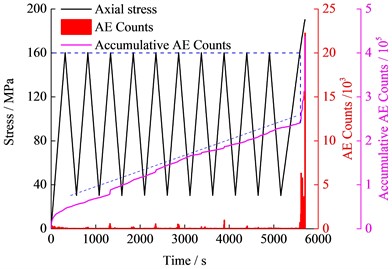
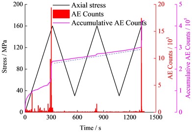
When the amplitude was 130 MPa, the accumulative AE Counts of the specimens increased approximately linearly with time in the cyclic loading stage. The AE phenomenon appeared whether in the loading or unloading sections in each cycle, and the generation rates were generally the same. Also, a Felicity effect could be observed under this amplitude cyclic loading. In the loading to failure stage, the AE Counts increased rapidly when the stress exceeded the maximum of cyclic loading, so the Kaiser effect could still occur. Particularly for the specimen I-13, the upper limit of the cyclic loading was close to the uniaxial strength, so the AE characteristics were worth analysing. As shown in Fig. 6(d), the accumulative AE Counts in the initial loading stage, and the cyclic loading stage accounts for about 55 % of the total AE Counts. The AE characteristics of the specimen I-13 under the cyclic loading stage was similar to that of the specimen I-17, but the increasing rate of I-13 was relatively larger.
It can be seen that the accumulative AE Counts in the cyclic loading stage was gradually increased with increasing amplitude, and the total AE Counts at completion of the failure process also increased gradually. New microcracks kept opening and closing under the cyclic loading and unloading, during which the AE phenomenon was generated. When the upper limit of the cyclic loading was close to the specimen strength, the AE phenomenon could occur at any stress under the cyclic loading stage, and the generation rate in the unloading section was the same as that in the loading section. The Kaiser effect was exhibited significantly under the cyclic loading of lower amplitude, and the Felicity effect began to reflect with increasing cyclic loading amplitude, but both of them occurred at any amplitude.
4.3. Relationship between specimen AE characteristics and radial deformation
Regardless of the cyclic loading amplitude, there was no great sudden change in the stress-axial strain curves, and the specimen seemed stable and scarcely damaged before reaching peak stress. However, the AE Characteristics showed that the specimen damage before peak loading could not be ignored, especially under larger amplitude. Therefore, it is difficult to reflect specimen damage process according to the axial deformation characteristics. It can be easily found that the sudden increase point of the radial strain corresponds to a large AE Counts. For example, the radial strain of the specimen Ⅰ-17 suddenly increased near the maximum of the cyclic loading in the third cycle and the corresponding AE Counts also suddenly increased. However, the axial strain did not exhibit such abrupt change. It can be seen that the radial deformation of the specimen was more closely related to the AE characteristics. Also, the final split failure mode (Fig. 7(c)) of the limestone specimens shows that the radial deformation was more significant when the specimen was close to failure. Therefore, the acoustic emission phenomenon of the limestone specimens is mainly due to the formation of new microcracks in the axial or approximate axial direction.
At a lower stress level, the initiation and propagation of the most microcracks did not appear, so the AE phenomenon was very rare under the cyclic loading stage, or the phenomenon was too weak to be detected (less than 40 dB). With increasing stress level, some microcracks began to appear and expand but did not form a larger failure surface which could significantly impact the specimen instability and failure, therefore specimens under amplitude of 85 MPa tended to be relatively stable after several cyclic loading and unloading. With the stress level further increasing, additional microcracks were created, which subsequently expanded, merged and developed in a stable trend in each cycle, both in the loading sections and unloading sections.
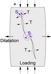
Under the loading sections of the cyclic loading, one can easily understand that the new cracks were initiated at the tips of the original microfractures under the axial loading. Tension and shearing action was mainly exhibited in the fracture surfaces, which resulted in energy-releasing and elastic wave generation, as shown in Fig. 7(a). For the unloading sections, the accumulative AE Counts in the unloading sections was almost the same as that in the loading sections under higher amplitudes and stress levels, such as specimen Ⅰ-13 and Ⅰ-17, thereby showing that the specimens also released energy and could generate a large number of waves in the deformation recovery process of the unloading sections. However, the AE generation mechanism in the unloading sections was different from that of loading sections. Fig. 7(b) shows the possible specimen deformation and the crack initiation and expansion characteristics during the unloading section. With the slow recovery of the axial deformation, the radial deformation recovered gradually. Since rock is a heterogeneous material, the energy agglomeration is different in the different parts under axial loading, and the various parts will produce different deformation recovery in the unloading process. Therefore, an uneven axial deformation may occur on both sides of the fracture surfaces, leading to the shear or tension actions at the tips of the fractures (location 1) and the extrusion dislocation between the crack surfaces (location 2). Besides, in the radial deformation recovery process, the shear action (location 3) may also appear between the adjacent fracture tips in the opposite direction from the loading process. Therefore, the plastic area will also be produced near the fracture surfaces and tips in the unloading sections, which caused the specimen damage to be intensified.
The new crack generation and propagation process are complex during the cyclic loading, and only the several possible forms are listed above. In general, the radial deformation of the limestone specimens was more unstable under the cyclic loading than axial deformation, and the vertical new cracks tend to initiate and propagate more easily, which leads to the specimen damage and the occurrence of AE phenomena.
Fig. 7Crack initiation and propagation in deformation and failure process of specimens during loading and unloading process
a) Loading section
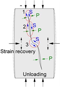
b) Unloading section
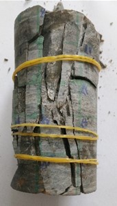
c) Brittle splitting failure morphology of limestone
5. Specimen damage evolution based on AE Counts
The relevant physical and mechanical parameters of the specimen will vary with the change of damage in the cyclic loading and unloading process. Therefore the damage variable can be characterized by the wave velocity [34], the elastic modulus [31], the crack volume strain [35] amongst others. It is nonetheless not appropriate to define the damage of high strength and brittleness limestone specimens by these parameters. The AE phenomenon reflects the rock damage characteristics, and the AE characteristic parameters are closely related to the rock damage evolution [35, 36]. Therefore, the damage evolution characteristics during the deformation and failure process can be characterised properly by the AE Counts.
Regarding the damage corresponding to failure as completed damage, the damage variable of the specimen can be calculated by the following equation:
where D represents the damage variable, N is the current AE Counts, Na is the accumulative AE Counts in the whole failure process.
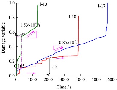
The accumulative AE Counts were different under the cyclic loading of different amplitudes, which showed that the damage evolution process of the specimen should be different. It is not convenient to compare the specimen damage evolution with time under each amplitude loading when defining rock damage based on their respective accumulative AE Counts. Therefore, the accumulative AE Counts of the specimen I-17, which is the largest among all the specimens, was used as the value of Na. The derived damage variable-time history curves under the different amplitudes are shown in Fig. 8. It can be seen that the specimen damage degree under cyclic loading of different amplitudes was different, and the smallest damage was only 0.256 when the amplitude was equal to 40 MPa. Although the amplitude of the specimen I-13 and I-17 were the same, as well as the accumulative damage were relatively similar, the damage in the initial cycle loading section, as well as the damage increasing rate in the cyclic loading stage, were greater in the specimen I-13 than in the specimen I-17, because of the higher stress level.
In the whole failure process of the specimen, it is very important to explore the damage variable in the cyclic loading stage. The damage variables in the cyclic loading stage under the three amplitudes are shown in Fig. 9. The data show that the specimen damage degree is related to the amplitude and stress level of the cyclic loading. Little damage was caused in the loading and unloading sections at 40 MPa amplitude cyclic loading, as shown in Fig. 9(a). With increasing amplitude and stress level, the specimen damage was increased, and the damage variables in the unloading sections of the 2nd and 5th cycles were even greater than that in the loading sections of the same cycles, as shown in Fig. 9(b). It appears clearly from the variation characteristics of the AE Counts in Fig. 6(b) that the specimen damage mainly occurred near the upper limit of the cyclic loading. The further increase of the amplitude (130 MPa) caused the damage variable to increase rather linearly with the cycle number, as shown in Fig. 9(c). Fig. 8 shows that the damage increasing rate at any stress level in the loading and unloading sections remained unchanged. Also, it can be found by analysing the damage variable of the specimen I-13 and I-17 that the increasing linear trend of the damage seemed was little affected by the discreteness of the specimens, and the damage increase rate was greater with increasing stress level. One can, therefore, speculate that if the cycle number increased continuously, the damage variable of the specimen I-17 would eventually reach a certain maximum, and failure would subsequently occur after another 13 cycles.
Fig. 8Damage variable-time evolution curves under cyclic loading with different amplitudes
The specimen damage in the loading and unloading sections can be discussed separately by defining the AE Counts. Under the different amplitudes cyclic loading, the stress states are different and new cracks initiate with different expansion process, so the resulting damage degrees consequently differ. The AE characteristics of the specimens are closely related to the radial deformation, and the relationship between them has been analysed in Section 4.3. From now onwards, the damage variable trend is considered to be consistent with the accumulative AE Counts, and the specimen damage and the radial deformation have a similar relationship.
6. Discussions
The analysis of the accumulative AE Counts of the specimen shows that AE Counts under a high amplitude cyclic loading was larger than that of uniaxial loading. As for the test piece I-10, the accumulative AE Counts were lower than that of the specimen I-4 because the cyclic loading with small amplitude and upper limit induced little damage on the specimens besides the specimen discreteness. The specimen loading process is a process of energy input and transformation. Compared with the uniaxial loading, the specimen energy input is relatively slow in the process of cyclic loading and unloading at the same loading rate. For example, the strength of the specimen I-13 was close to I-4, but the duration under cyclic loading was about two times the latter. As a result, the accumulative damage at the whole failure process of the specimen I-13 was four times of the specimen I-4, indicating that specimen could absorb more energy under the cyclic loading before failure.
Fig. 9Damage variable in loading and unloading sections of different cycles, where Dl, Du is damage variable in loading section and unloading section respectively, and Da is accumulative damage variable in each cycle
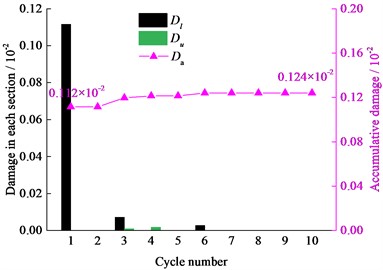
a) Amplitude of 40 MPa
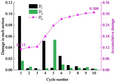
b) Amplitude of 85 MPa
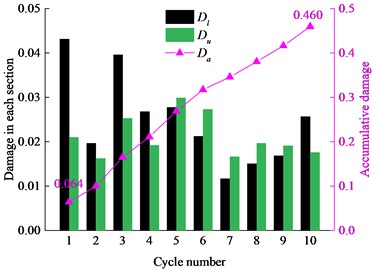
c) Amplitude of 130 MPa
In underground excavation process, the energy accumulation is easily generated in the high stress surrounding rock mass, which increases the risk of rock burst. Limestone specimen has strong elastic and brittleness characteristics, and the failure process is relatively intense, which is similar to the occurrence of rock burst and no clear signs occurred when the specimen was about to be destroyed. Besides, the surrounding rock mass is often affected by the advancement of the heading face or the construction of adjacent roadways or chambers and exhibit a periodic stress state. If the energy dissipation of the rock mass before failure could be controlled as much as possible, it would greatly benefit for relieving energy accumulation and reducing the rock burst tendency of the surrounding rock mass. Therefore, for the engineering construction of the rock mass with a rock burst tendency, proper driving speed and single excavation step should be controlled to prevent the direct failure of the surrounding rock mass because the stress state of the surrounding rock mass is greater than the ultimate strength of rock mass. Obviously, the stress on specimen should be kept in its pre-failure stage as far as possible, so as to consume as much as accumulated elastic energy in the surrounding rock mass.
7. Conclusions
With the help of the AE technology, constant amplitude cyclic loading test on limestone specimens with strong strength and brittleness were completed using MTS 816 rock mechanics test system. The main conclusions could be summarised as follows:
1) The limestone specimens exhibited obvious elastic-brittle failure characteristics, and their radial deformations were more easily affected by the cyclic loading than axial deformation. The apparent radial residual strain of the specimens could be partially recovered from a higher stress state to a lower stress state under cyclic loading with an amplitude of 130 MPa.
2) The AE characteristics of specimens were closely related to radial deformations. The specimens exhibited significant Felicity effect under the cyclic loading of higher amplitudes and stress levels. However, the Kaiser effect always manifested regardless of the amplitude. The AE activity was significant during both the loading and unloading sections.
3) The specimen damage was related to the amplitude of the cyclic loading. The larger was the amplitude, and the more severe was the specimen damage. When the amplitude of the cyclic loading was 130 MPa, the damage generation rate at any stress state in unloading sections was equal to that in the loading sections, which could well reflect the specimen damage variation under cyclic loading by AE Counts.
4) In engineering practice, the reasonable excavation parameters should be set such that the hard and brittle rock mass with impact tendency and periodic loading state could be kept before peak stress, which could subsequently minimise the impact liability by consuming more accumulative energy.
References
-
C. Martin, “The strength of massive Lac du Bonnet granite around underground openings,” Ph.D. thesis, University of Manitoba, Canada, 1993.
-
C. Yang, W. Shi, X. Qian, and X. Peng, “Deformation and failure mechanism of bedding slopes induced by underground mining: case study from Yanwan Village, Guizhou Province, China,” Geotechnical and Geological Engineering, Vol. 41, No. 3, pp. 1877–1891, Jan. 2023, https://doi.org/10.1007/s10706-023-02377-w
-
J. Dang, M. Tu, X. Zhang, and Q. Bu, “Research on the bearing characteristics of brackets in thick hard roof mining sites and the effect of blasting on roof control,” Geomechanics and Geophysics for Geo-Energy and Geo-Resources, Vol. 10, No. 1, Jan. 2024, https://doi.org/10.1007/s40948-024-00735-3
-
J. Ning, J. Wang, J. Jiang, S. Hu, L. Jiang, and X. Liu, “Estimation of crack initiation and propagation thresholds of confined brittle coal specimens based on energy dissipation theory,” Rock Mechanics and Rock Engineering, Vol. 51, No. 1, pp. 119–134, Sep. 2017, https://doi.org/10.1007/s00603-017-1317-9
-
Q. Meng, M. Zhang, L. Han, H. Pu, and T. Nie, “Effects of acoustic emission and energy evolution of rock specimens under the uniaxial cyclic loading and unloading compression,” Rock Mechanics and Rock Engineering, Vol. 49, No. 10, pp. 3873–3886, Aug. 2016, https://doi.org/10.1007/s00603-016-1077-y
-
A. Fathi, Z. Moradian, P. Rivard, and G. Ballivy, “Shear mechanism of rock joints under pre-peak cyclic loading condition,” International Journal of Rock Mechanics and Mining Sciences, Vol. 83, pp. 197–210, Mar. 2016, https://doi.org/10.1016/j.ijrmms.2016.01.009
-
X. Yang et al., “Mechanical response characteristics and permeability evolution of coal samples under cyclic loading,” Energy Science and Engineering, Vol. 7, No. 5, pp. 1588–1604, Jun. 2019, https://doi.org/10.1002/ese3.368
-
B. Zhang et al., “Effect of stress amplitude on mechanical and acoustic emission of sandstone under constant-cyclic loading,” Bulletin of Engineering Geology and the Environment, Vol. 82, No. 7, Jun. 2023, https://doi.org/10.1007/s10064-023-03307-z
-
X. Sun, Z. Chen, and Q. Zou, “Mechanical properties and energy evolution characteristics of borehole-containing specimens under disturbances of cyclic incremental stress with different lower limits,” Journal of Materials Research and Technology, Vol. 25, pp. 4187–4200, Jul. 2023, https://doi.org/10.1016/j.jmrt.2023.06.197
-
Y. R. Zhao, H. Q. Yang, L. P. Huang, R. Chen, X. S. Chen, and S. Y. Liu, “Mechanical behavior of intact completely decomposed granite soils along multi-stage loading-unloading path,” Engineering Geology, Vol. 260, p. 105242, Oct. 2019, https://doi.org/10.1016/j.enggeo.2019.105242
-
J. Liu, H. Xie, Z. Hou, C. Yang, and L. Chen, “Damage evolution of rock salt under cyclic loading in unixial tests,” Acta Geotechnica, Vol. 9, No. 1, pp. 153–160, May 2013, https://doi.org/10.1007/s11440-013-0236-5
-
S.-L. Qiu, X.-T. Feng, J.-Q. Xiao, and C.-Q. Zhang, “An experimental study on the pre-peak unloading damage evolution of marble,” Rock Mechanics and Rock Engineering, Vol. 47, No. 2, pp. 401–419, Mar. 2013, https://doi.org/10.1007/s00603-013-0394-7
-
H. Wang, M. Fall, and S. Miao, “Characteristics of fracture changes and fatigue failure signals for siltstone under cyclic loading,” International Journal of Rock Mechanics and Mining Sciences, Vol. 174, p. 105645, Feb. 2024, https://doi.org/10.1016/j.ijrmms.2024.105645
-
M. N. Bagde and V. Petroš, “Fatigue and dynamic energy behaviour of rock subjected to cyclical loading,” International Journal of Rock Mechanics and Mining Sciences, Vol. 46, No. 1, pp. 200–209, Jan. 2009, https://doi.org/10.1016/j.ijrmms.2008.05.002
-
X. Zhu, Y. Li, C. Wang, X. Sun, and Z. Liu, “Deformation failure characteristics and loading rate effect of sandstone under uniaxial cyclic loading and unloading,” Geotechnical and Geological Engineering, Vol. 37, No. 3, pp. 1147–1154, Aug. 2018, https://doi.org/10.1007/s10706-018-0674-9
-
K. Khaledi, E. Mahmoudi, M. Datcheva, and T. Schanz, “Stability and serviceability of underground energy storage caverns in rock salt subjected to mechanical cyclic loading,” International Journal of Rock Mechanics and Mining Sciences, Vol. 86, pp. 115–131, Jul. 2016, https://doi.org/10.1016/j.ijrmms.2016.04.010
-
Y. Guo, C. Yang, and H. Mao, “Mechanical properties of Jintan mine rock salt under complex stress paths,” International Journal of Rock Mechanics and Mining Sciences, Vol. 56, pp. 54–61, Dec. 2012, https://doi.org/10.1016/j.ijrmms.2012.07.025
-
A. Momeni, M. Karakus, G. R. Khanlari, and M. Heidari, “Effects of cyclic loading on the mechanical properties of a granite,” International Journal of Rock Mechanics and Mining Sciences, Vol. 77, pp. 89–96, Jul. 2015, https://doi.org/10.1016/j.ijrmms.2015.03.029
-
Z. Mo et al., “Stress threshold determination method and damage evolution modelling based on micritic bioclastic limestone,” Rock Mechanics and Rock Engineering, Vol. 57, No. 1, pp. 45–60, Nov. 2023, https://doi.org/10.1007/s00603-023-03524-8
-
E. Eberhardt, D. Stead, and B. Stimpson, “Quantifying progressive pre-peak brittle fracture damage in rock during uniaxial compression,” International Journal of Rock Mechanics and Mining Sciences, Vol. 36, No. 3, pp. 361–380, Apr. 1999, https://doi.org/10.1016/s0148-9062(99)00019-4
-
A. M. Naji, M. Z. Emad, H. Rehman, and H. Yoo, “Geological and geomechanical heterogeneity in deep hydropower tunnels: A rock burst failure case study,” Tunnelling and Underground Space Technology, Vol. 84, pp. 507–521, Feb. 2019, https://doi.org/10.1016/j.tust.2018.11.009
-
X. Chen, L. Li, L. Wang, and L. Qi, “The current situation and prevention and control countermeasures for typical dynamic disasters in kilometer-deep mines in China,” Safety Science, Vol. 115, pp. 229–236, Jun. 2019, https://doi.org/10.1016/j.ssci.2019.02.010
-
V. N. Khashin and V. S. Ludzish, “Some rock-burst characteristics in pits of the Prokop’evsk coal field of the Kuzbass,” Soviet Mining Science, Vol. 10, No. 2, pp. 209–214, Mar. 1974, https://doi.org/10.1007/bf02501820
-
Y. Li, G. Su, J. Pang, C. Liu, Q. Zhang, and X. Yang, “Mechanism of structural-slip rockbursts in civil tunnels: an experimental investigation,” Rock Mechanics and Rock Engineering, Vol. 54, No. 6, pp. 2763–2790, Mar. 2021, https://doi.org/10.1007/s00603-021-02429-8
-
K. Arora, T. Chakraborty, and K. S. Rao, “Experimental study on stiffness degradation of rock under uniaxial cyclic sinusoidal compression loading,” Rock Mechanics and Rock Engineering, Vol. 52, No. 11, pp. 4785–4797, May 2019, https://doi.org/10.1007/s00603-019-01835-3
-
X. Li et al., “The influence of the internal structure of loaded composite coal-rock on the variation characteristics of electromagnetic radiation (EMR) signal,” Journal of Applied Geophysics, Vol. 213, p. 105027, Jun. 2023, https://doi.org/10.1016/j.jappgeo.2023.105027
-
L. Ma, Y. Zhang, K. Cao, and Z. Wang, “An experimental study on infrared radiation characteristics of sandstone samples under uniaxial loading,” Rock Mechanics and Rock Engineering, Vol. 52, No. 9, pp. 3493–3500, Jan. 2019, https://doi.org/10.1007/s00603-018-1688-6
-
Q. Meng, Y. Chen, M. Zhang, L. Han, H. Pu, and J. Liu, “On the kaiser effect of rock under cyclic loading and unloading conditions: insights from acoustic emission monitoring,” Energies, Vol. 12, No. 17, p. 3255, Aug. 2019, https://doi.org/10.3390/en12173255
-
K. Du, X. Luo, M. Liu, X. Liu, and J. Zhou, “Understanding the evolution mechanism and classification criteria of tensile – shear cracks in rock failure process from acoustic emission (AE) characteristics,” Engineering Fracture Mechanics, Vol. 296, p. 109864, Feb. 2024, https://doi.org/10.1016/j.engfracmech.2024.109864
-
Q. Xiong, Q. Lin, and J. C. Hampton, “Structural control within flawed rock specimens under external loading as visualized through repeating nucleation on multiple sites by acoustic emission (AE),” Geophysical Journal International, Vol. 233, No. 1, pp. 490–509, Nov. 2022, https://doi.org/10.1093/gji/ggac470
-
J.-Q. Xiao, D.-X. Ding, F.-L. Jiang, and G. Xu, “Fatigue damage variable and evolution of rock subjected to cyclic loading,” International Journal of Rock Mechanics and Mining Sciences, Vol. 47, No. 3, pp. 461–468, Apr. 2010, https://doi.org/10.1016/j.ijrmms.2009.11.003
-
C. Li and E. Nordlund, “Experimental verification of the Kaiser effect in rocks,” Rock Mechanics and Rock Engineering, Vol. 26, No. 4, pp. 333–351, Jan. 1993, https://doi.org/10.1007/bf01027116
-
Y. Zhang, Y. Chen, R. Yu, L. Hu, and M. Irfan, “Effect of loading rate on the felicity effect of three rock types,” Rock Mechanics and Rock Engineering, Vol. 50, No. 6, pp. 1673–1681, Feb. 2017, https://doi.org/10.1007/s00603-017-1178-2
-
T. Kawamoto, Y. Ichikawa, and T. Kyoya, “Deformation and fracturing behaviour of discontinuous rock mass and damage mechanics theory,” International Journal for Numerical and Analytical Methods in Geomechanics, Vol. 12, No. 1, pp. 1–30, Jul. 2005, https://doi.org/https://doi.org/10.1002/nag.1610120102
-
J.-S. Kim, K.-S. Lee, W.-J. Cho, H.-J. Choi, and G.-C. Cho, “A comparative evaluation of stress-strain and acoustic emission methods for quantitative damage assessments of brittle rock,” Rock Mechanics and Rock Engineering, Vol. 48, No. 2, pp. 495–508, Apr. 2014, https://doi.org/10.1007/s00603-014-0590-0
-
M. S. Diederichs, P. K. Kaiser, and E. Eberhardt, “Damage initiation and propagation in hard rock during tunnelling and the influence of near-face stress rotation,” International Journal of Rock Mechanics and Mining Sciences, Vol. 41, No. 5, pp. 785–812, Jul. 2004, https://doi.org/10.1016/j.ijrmms.2004.02.003
About this article

This work was supported by the Scientific Research Foundation for High-level Talents of Anhui University of Science and Technology (Grant numbers 2021yjrc31), the National Natural Science Foundation of China (Grant numbers 52274071), the Anhui Provincial Natural Science Foundation (Grant numbers 2208085QE174) and the Anhui University of Science and Technology Graduate Student Innovation Fund (Grant numbers 2023CX2050).
The datasets generated during and/or analyzed during the current study are available from the corresponding author on reasonable request.
All authors contributed to the study conception and design. Material preparation, data collection and analysis were performed by Qi An, Chengjie Li, Guoqiang Fan, Ying Xu, Shoudong Xie, and Yanghaonan Jiao. The first draft of the manuscript was written by Qi An and Chengjie Li and all authors commented on previous versions of the manuscript. All authors read and approved the final manuscript.
The authors declare that they have no conflict of interest.
