Abstract
Banana-shaped Vibrating-Dewatering Screen (BVDS) is effective for dehydrate and demud sand aggregate, fine coal slime, ore and other materials. In this paper, the mechanical structure of the BVDS was revealed by means of theoretical modeling, simulation research and experimental test, and its dynamic and vibration characteristics were studied. The mathematical model was established, and the dynamic curve and spatial trajectory of the BVDS were obtained by MATLAB/Simulink software. Lissajous displacement diagram shows that the spatial motion trajectory of the shaker is an oblique line. The vibration test was carried out by using dynamic characteristic test system, and the dynamic characteristics of displacement, velocity and acceleration of the BVDS were revealed. Finally, through theoretical analysis, the changing trend of vibration characteristics of the BVDS with the increase of rotating velocity was obtained. The results show that the experimental data is basically consistent with the theoretical data, and the deviation is less than 6.58 %, which verifies the accuracy of the theoretical model. This paper provides a reference for the design and efficient operation of the BVDS.
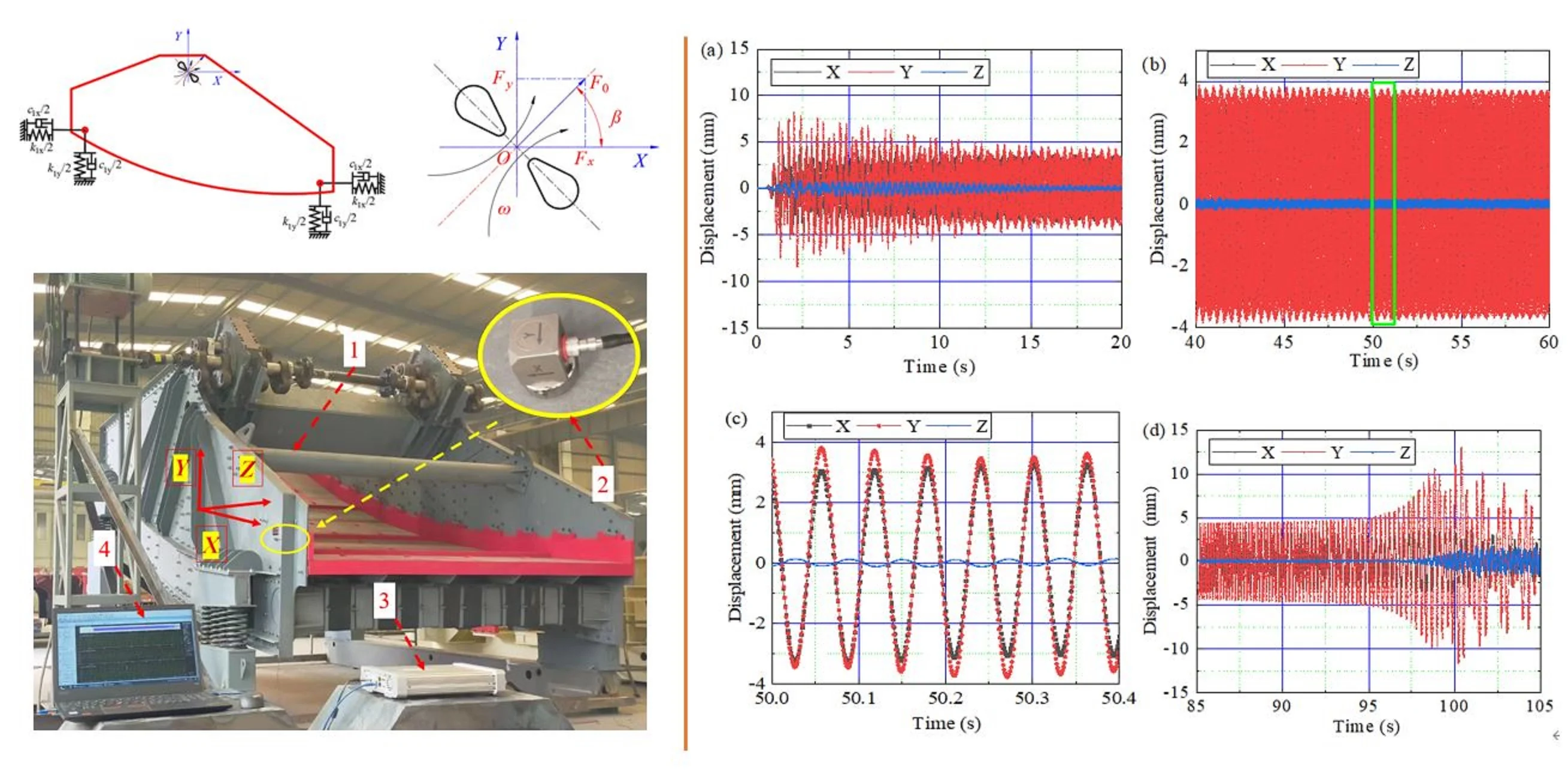
Highlights
- A dynamic model of the banana-type vibrating dewatering screen was proposed.
- The dynamic experiment was carried out and the results were analyzed.
- The dynamic characteristic of the screen body were obtained.
1. Introduction
Screening plays an important role in classification, dewatering, medium draining, and desliming [1-4]. The main function of vibrating dewatering screen is to dehydrate and demud sand aggregate, fine coal slime, ore and other materials to improve product quality and product use effect [5, 6]. Excellent dewatering and screening performance is the guarantee of improving economic benefits of the vibrating dewatering screen [7-10]. The use of vibration dewatering screen is generally harsh, the work time is long, and there are problems in the use of running noise, key parts are easy to damage, and the overall service life is low [11-15].
To date, many researchers have conducted numerous studies on the dynamic response stability of vibrating dewatering screen. In order to improve the dewatering performance, Dong [16, 17] developed a vibration dewatering screen with a unique structure excited by a side plate beam, coupled with a wavy screen plate, which is suitable for dewatering of final cleaned coal. The application of low-frequency and high-amplitude vibration parameters improves the processing capacity and screening efficiency of the screen machine. Li [18] studied the application of vibrating dewatering screen in tailings dewatering system, which increased the utilization rate of recovered water from only about 70 %-75 % to more than 95 %, realizing zero drainage in production and huge economic and social benefits. Zhang [19] studied the process flow and production index of tailings treatment with high-frequency vibration dewatering screen, which was successfully applied in tailings treatment and obtained tailings with water content less than 15 %. The vibrating dewatering screen also plays an important role in the construction industry. An [20] used the vibrating dewatering screen to separate sludge and mud, reduce the discharge of waste mud, and improve the environment of the construction site.
Furthermore, the vibration characteristics of the screen body were also investigated extensively. Fang [21] investigated and analyzed the dynamic characteristics of the vibrating screen using the Lyapunov method and numerical simulation. Jiang [22] found that the loading material has an obvious influence on the modal shapes. These investigations indicated that ordinary vibrating screens working in the far-resonance region is beneficial to the systems stability. Baragetti [23] presented an innovative design strategy validated using full-scale experimental tests for the optimization of the kinematic performances and the structural loads of heavy loaded vibrating screens. Jiang [24] proposed a novel large vibrating screen driven externally by an unbalanced two-axle excitation and investigated the kinematics characteristics of the screen and particle moving behavior under different operational conditions. Through theory and experiment, Li studied the vibration characteristics of the flip-flow screen, and the experiment results can be fully described by the theory model [25].
There are few complete theories for the dynamic characteristics of the Banana-shaped Vibrating-Dewatering Screen (BVDS). In this work, a dynamical model of the BVDS was established. The vibration characteristic of the BVDS based on the dynamical model was studied by MATLAB/Simulink method and the reasonability was verified by vibration experiment. Besides, the effect of the rotational velocity on the vibration characteristics of the BVDS was investigated parametrically. The results of this study are helpful for understanding the dynamic characteristics of the BVDS, and this study provides a reference for the optimal design and efficient operation of this kinds of vibration screen.
2. Model constructions
The mechanical structure of the BVDS is shown in Fig. 1. The BVDS is composed of two parts: power system and main structure. The power system is composed of 1 drive motor, 2 belt transmission system, 3 universal coupling and other components. The main structure consists of 4 eccentric excitation system, 5 screen body, 6 screen surface and 7 springs.
Fig. 1Mechanical structure of the Banana-shaped Vibrating-Dewatering Screen (BVDS)
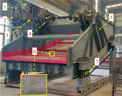
The motor drives the eccentric excitation system to rotate through the belt drive system and the universal coupling, then the screen body and screen surface vibrate regularly under the excitation force. The screen surface is curved, so it is called banana type screen. The material is thrown up on the screen surface and moves forward in a skipping straight line, so as to achieve the purpose of screening and grading the material. The vibration strength of the screen is closely related to the screening performance of the BVDS. Therefore, revealing the dynamic characteristics of banana-type vibrating dewatering screen and exploring its vibration behavior play a key role in fully understanding the working performance of the BVDS. In order to explore the working mechanism of the BVDS, all the parameters used in this paper are measured from the field objects in equal proportion.
The dynamic model of BVDS is shown in Fig. 2. According to the dynamic model, the vibration parameters such as displacement, velocity and acceleration can be obtained. As the natural properties of BVDS, these parameters provide an important basis for evaluating the rationality and reliability. In the working process of the BVDS, the two eccentric blocks do synchronous and reverse rotation, and the exciting force generated in the direction of the parallel two rotation center line cancels each other, and is superimposed in the direction perpendicular to the resultant force. The eccentric block makes uniform circular motion and produces periodic harmonic excitation force. The displacement, velocity and acceleration of the screen body are constantly changing because of the reciprocating motion of the screen body which similar to a straight line. In order to study the motion characteristics of the screen body, the absolute coordinate system is established with the rotation center of the exciter as the origin O, in which the -axis is parallel to the horizontal mounting plane and points to the discharge direction, and the -axis is perpendicular to the ground. According to the working principle of the BVDS, the eccentric block, screen body and spring of the exciter are simplified.
Fig. 2Dynamic model of the BVDS

When the eccentric blocks rotate, the exciting force () is directional harmonic force. The exciting force in horizontal and vertical directions can be obtained through Eq. (1):
where, , is the angular velocity of the vibration exciter, is the rotational velocity of the vibration exciter; is the total excitation force; is the angle between vibration direction and -direction.
The second order differential equation of the vibration system can be calculated by Eq. (2):
where, is the total mass of the screen body; , , and are the displacement, velocity, acceleration of the screen body along -direction, respectively; , , and are the displacement, velocity, acceleration of the screen body along -direction, respectively; , are the equivalent stiffness and damping coefficients of the springs along -direction, respectively; , are the equivalent stiffness and damping coefficients of the springs along -axis, respectively.
Assuming that the displacement in horizontal and vertical directions (, ) has the following forms:
Taking the first-order and second-order derivative of to time , the velocity and acceleration can be calculated through Eq. (4) and (5):
Substituting Eqs. (3-5) into Eq. (2), the displacement amplitude (, ) and phase angle (, ) can be obtained:
3. Experiment set up
The dynamic characteristics experiment and test analysis system of the BVDS are shown in Fig. 3. The system mainly includes: circuit breaker, BVDS, ICP three-way acceleration sensor, cable, INV3060S multi-channel signal acquisition instrument, Coinv DASP multi-channel signal real-time analysis software.
Fig. 3Dynamic characteristic experiment and test analysis system: 1 – BVDS, 2 – ICP three-direction acceleration sensor, 3 – INV3060S multi-channel signal acquisition instrument, 4 – Coinv DASP multi-channel signal real-time analysis software
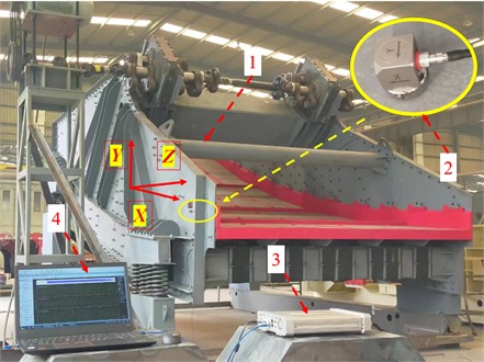
The ICP (Integrated Circuit Piezoelectric) sensor is an integrated circuit piezoelectric sensor, which is widely used in the field of measurement and monitoring. It uses the principle of piezoelectric effect to convert physical quantities such as pressure, acceleration or vibration into corresponding electrical signals. The ICP three-way acceleration sensor can measure the acceleration of , , and directions respectively. The ICP three-direction acceleration sensor is adsorbed on the measurement point of the BVDS by magnetic base. The -axis direction of the three-way acceleration sensor is parallel to the ground, the -axis direction is perpendicular to the ground, and the -axis direction is perpendicular to the side plate of the screen body. The three-way acceleration sensor is connected to the INV3060S multi-channel acquisition device by cable. The sampling frequency of the multi-channel acquisition device is set to 1024 Hz. The multi-channel acquisition device is connected via a network cable to a laptop computer with Coinv DASP software installed. Before the test, first check the line, then turn on the circuit breaker to turn on the power, and then turn on the Coinv DASP software test system for data collection. Start the motor, record about 60 s, turn off the motor. When the BVDS is completely stationary, stop collecting signals and save data. The collected acceleration signal is transmitted to the computer through cable, multi-channel data acquisition instrument and network cable, and then DASP software is used to analyze the collected signal in time domain.
4. Results and discussion
4.1. Dynamic analysis based on MATLAB/Simulink
In order to further analyze the dynamic characteristics of the BVDS, the simulation model was established based on the MATLAB/Simulink simulation module, and the specific parameters are shown in Table 1. The simulation models of and directions of the BVDS are shown in Fig. 4. Use the Sine Wave in the Sources module library as the sine excitation signal. The Scope oscilloscope in receiver module library is used to output displacement, velocity and acceleration signal curves.
Table 1Parameters of the BVDS
Parameters | Value |
, (kg) | 13000 |
Rated velocity , (rpm) | 975 |
, (KN) | 650 |
, (N∙mm-1) | 1605 |
, (N∙mm-1) | 2292 |
Damping ratio | 0.01 |
Fig. 4Simulation model of the BVDS based on MATLAB/Simulink
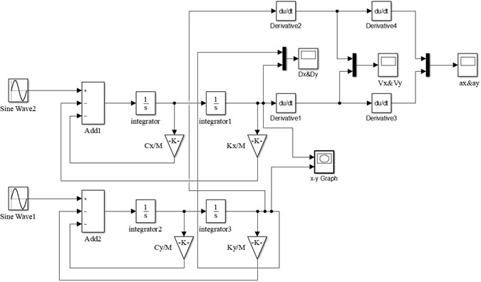
According to Table 1, the corresponding sinusoidal excitation was applied, the exciting angular velocity was set to 102.05 rad∙s-1 (975 rpm), and the simulation time was set to 10 s. The simulation result of displacement time domain response of the BVDS is shown in Fig. 5, and the Lissajous diagram of displacement during the stable period is shown in Fig. 6.
As can be seen from the simulation results in Fig. 5, when the BVDS is running at a set operating frequency, the screen body enters a state of disturbed vibration in the first 0-7 s, and the displacement amplitudes of the screen body in the and directions are relatively large. The maximum displacement amplitude in the direction is 5.36 mm, and the maximum displacement amplitude in the direction is 5.12 mm. After 7 s, the screen body entered the stable operation stage. In the stable stage, the displacement amplitude of the screen body in the and directions is about 3.45 mm. In addition, it can be found from the displacement curve that the phase difference of the screen body in the and directions is approximately equal to 0°. As can be seen from the Lissajous diagram of displacement during the stable stage in Fig. 6, the displacement trajectory of the screen body is a diagonal line of 45° along the direction.
Fig. 5Time-responses of displacement by MATLAB/Simulink simulation

Fig. 6Lissajous diagram of displacement by MATLAB/Simulink simulation
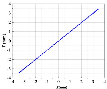
Fig. 7Time-responses of velocity by MATLAB/Simulink simulation

Fig. 8Time-responses of acceleration by MATLAB/Simulink simulation

The time domain response simulation results of velocity and acceleration for the BVDS along the and directions are shown in Fig. 7 and 8. Compared with the displacement curve, it takes less time for the velocity and acceleration waveforms in and directions to reach the stable value. The velocity and acceleration waveforms in the stable stage are standard sine waves. It can also be seen from Fig. 7 that the velocity amplitudes of the screen body in the and directions are stable at 350.72 and 352.50 mm∙s-1, respectively. It can also be seen from Fig. 8 that the acceleration amplitudes of the screen body in the and directions are 35.79 and 35.97 m∙s-2, respectively. The phase difference of the velocity and acceleration curves of the screen body in the and directions are approximately equal to 0°. The above MATLAB/Simulink simulation analysis results provide a solid theoretical basis for the development of the BVDS.
4.2. Vibration analysis based on the dynamic experiment
Fig. 9 shows the time-domain response curve of the screen body displacement of the BVDS in different time periods. The corresponding angular rotation velocity is 102.05 rad∙s-1 ( 975 rpm). The time-domain response process of displacement can be divided into three different stages: starting stage (0-20 s), stable operation stage (40-60 s) and shutdown stage (85-105s), and the displacement signals of each stage are significantly different. It can be seen that the main vibration direction of the vibration system is and axis. Relative to the and axes, the amplitude in the axis is small and negligible. According to the time-domain response results, the time-space characteristic curve of the displacement of the screen body position at different periods and the displacement Lissajous diagrams can be obtained. The results are shown in Fig. 10 and 11.
The displacement time domain response of the BVDS at starting stage (0-20 s) is shown in Fig. 9(a), with the angular velocity gradually increases from 0 to 102.05 rad∙s-1. In this process, when the vibration passes near the natural frequency of the screen body, the amplitude of the screen body increases significantly, making the vibrating screen appear resonance. The maximum displacement amplitude of the screen body in the direction reaches 4.74 mm, and the maximum displacement amplitude in the direction reaches 8.45 mm, which is significantly larger than the working amplitude. The BVDS has a large vibration and swing, and the displacement time-space characteristic curve and Lissajous diagrams are more complicated, as shown in Fig. 10(a) and Fig. 11(a).
After starting 20 s, the BVDS enters the steady stage. As can be seen from Fig. 9(b) and 9(c), the displacement waveform in and directions are sine wave, and the vibration amplitude is stable as working amplitude. The average displacement amplitude of the screen body in the direction is 3.27 mm, and the average displacement amplitude in the direction is 3.65 mm. The space-time curve is regular, as shown in Fig. 10(b), The displacement trajectory is a regular oblique line, as shown in Fig. 11(b).
Fig. 9Time domain response curves of displacement over different time periods
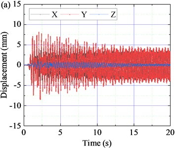
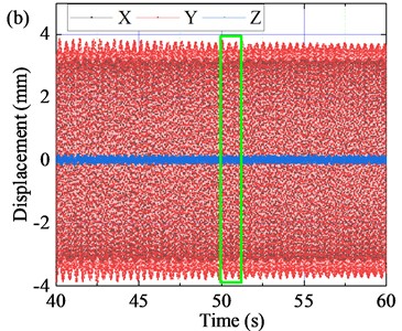
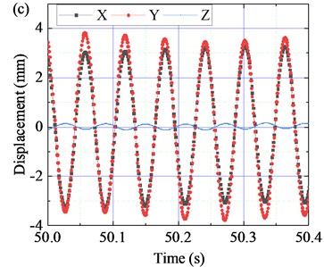
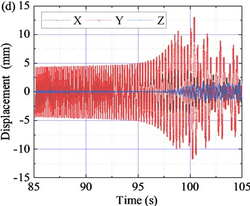
Fig. 10Time-space characteristic curve of displacement over different time periods
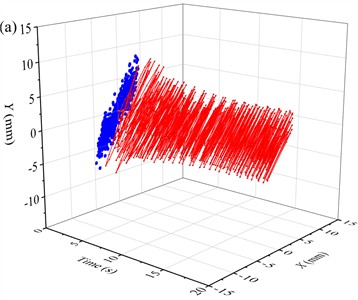
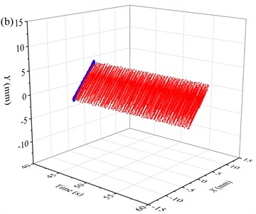
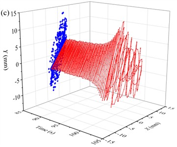
Fig. 11Lissajous diagrams of displacement over different time periods

Fig. 12Time-domain characteristic curves of velocity signals
The time-domain response of displacement in the shutdown stage is shown in Fig. 9(d). When the vibrating screen is in the shutdown stage for 85-105 s, the motor velocity and angular velocity gradually decrease. After passing through the resonance region again, the displacement in the direction increases slowly first and then decreases sharply. The displacement curve in the direction changes several times, and the vibration in the direction is more intense than that in the direction. The maximum displacement amplitude in direction and direction reaches 4.28 mm and 13.05 mm respectively. Similar to the starting stage, the displacement time-space characteristic curve and the Lissajous diagrams in the shutdown stage are also relatively complex, as shown in Fig. 10(c) and 11(c).
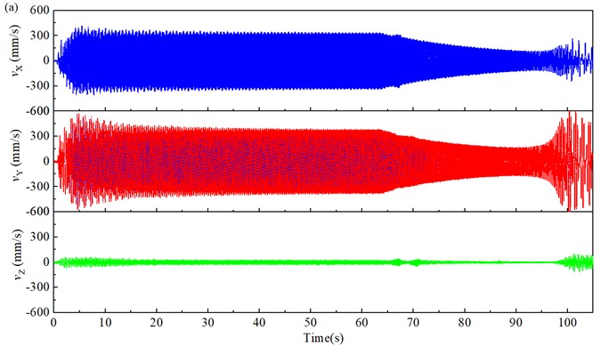
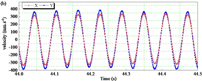
In addition, the velocity and acceleration of the screen body are also important index of the vibration intensity. Fig. 12 shows the time-domain velocity variation curve of the screen body along the and directions. The velocity of the screen body along the axis is smaller than that in the and directions. Similar to the time-domain response curve of displacement, the velocity curve of the screen body also has a phase difference of nearly 0°. The velocity of the screen body varies greatly during the starting and stopping stages, as shown in Fig. 12(a). The velocity amplitude of the screen body along the direction is close to 454.3 mm∙s-1 in the starting stage, and close to 720.4 mm∙s-1 in the stopping stage, which is much higher than the velocity amplitude in the stable operation stage. As shown in Fig. 12(b), the average velocity amplitude of the screen body in the direction is 336.21 mm∙s-1, and the average velocity amplitude along the direction is 365.87 m∙s-1. The velocity amplitude of the screen body along the direction is larger than that along the direction.
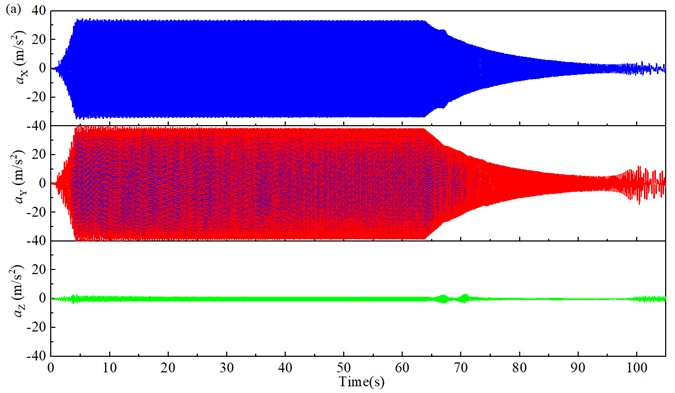
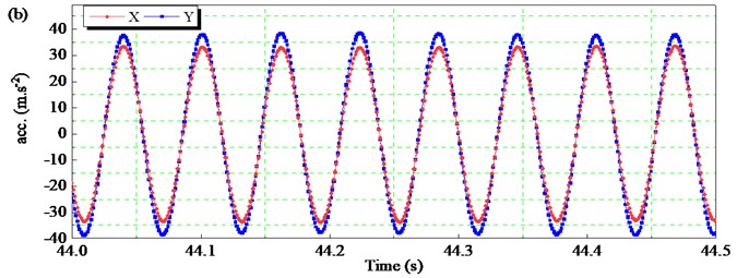
Fig. 13 shows the time-domain acceleration curve of the screen body along the and directions. Different from the time-domain response curves of displacement and velocity, the acceleration curve at the start and stop stages is relatively stable without drastic changes, as shown in Fig. 13(a). The maximum acceleration in the start-up and shutdown phases is close to that in the stable operation phase. As shown in Fig. 13(b), the average acceleration amplitude of the screen body in the direction is 33.58 m∙s-2, and the average acceleration amplitude in the direction is 37.56 m∙s-2. The amplitude of acceleration in the direction is slightly larger.
Fig. 13Time-domain characteristic curves of acceleration signals
The specific values of the experimental test results and theoretical results are compared, as shown in Table 2. It can be seen from the table that the experimental results of the motion characteristics of the vibrating screen have a strong agreement with the theoretical results. Under stable operation, the relative error between experimental results and theoretical results is less than 7 %, and the maximum error is 6.58 %. The experimental results show that the dynamic theoretical model can perfectly describe the motion of the BVDS.
Table 2Comparisons of Simulink and experimental results
Parameter | Simulink results | Experimental results | Error (%) |
(mm) | 3.44 | 3.27 | –5.10 |
(mm∙s-1) | 350.72 | 336.21 | –4.32 |
(m∙s-2) | 35.79 | 33.58 | –6.58 |
(mm) | 3.45 | 3.65 | 5.36 |
(mm∙s-1) | 352.50 | 365.87 | 3.65 |
(m∙s-2) | 35.97 | 37.56 | 4.23 |
4.3. Vibration characteristics with different rotational velocity
In this section, the influence of rotational velocity on the dynamic characteristics of the screen body of the BVDS is theoretically discussed. Other parameters are shown in Table 1. Based on Eq. (3), the curve of screen body amplitude under different rotational velocity is shown in Fig. 14.
As can be seen from Fig. 14(a), before the angular velocity reaches the resonant angular frequency, the amplitude of the screen body along the direction and the amplitude in the direction slowly increase with the increase of . When the angular velocity reaches the resonance region, the amplitude and increase sharply. When exceeds resonance region, the amplitude and decrease rapidly. Then the screen body enters the transition region and working region. In the transition region and working region, and decrease slowly with the increase of .
Fig. 14Vibration amplitude of the screen body under different ω
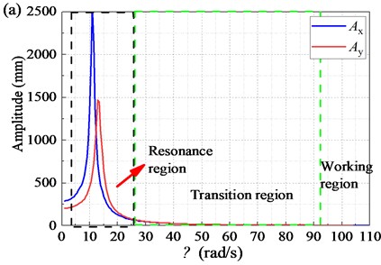
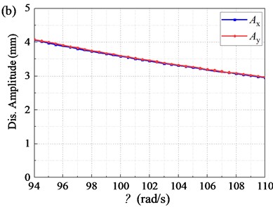
When the vibration is in the resonance region, the vibration amplitude of the screen body is too large, which leads to unstable running of the vibrating screen. When the vibration is in the transition region, the angular velocity is relatively slow, and the velocity and acceleration of the screen body are low, resulting in insufficient vibration strength and low screening performance. As shown in Fig. 14(b), when the vibration is in the working region, the amplitude of the screen body gradually becomes smaller, the vibration is relatively stable, and high screening performance can be obtained in practice. Moreover, when the angular velocity is too high, the alternating load imposed on the spring and the machine noise will increase, while reducing the service life of the machine.
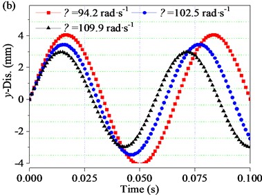
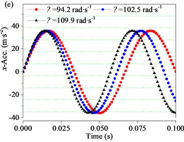
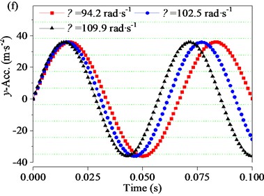
In order to further investigate the effect of the angular velocities in the working region on the dynamic properties of the screen body, the angular velocities of 94.2, 102.05, and 109.9 rad∙s-1 (i.e. of 900, 975, and 1050 rpm, respectively) were taken for discussion. The time-domain changes of displacement, velocity, acceleration (, , ) and (, , ) of the screen body along the and directions under different angular velocities are shown in Fig. 15. In general, with the increase of angular velocity, the displacement amplitude of the screen body decreases obviously, the velocity amplitude decreases slightly, and the acceleration amplitude is basically unchanged.
Fig. 15Vibration characteristics of the screen body at different ω
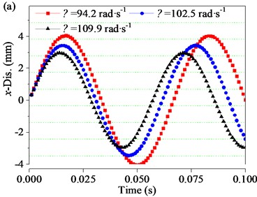
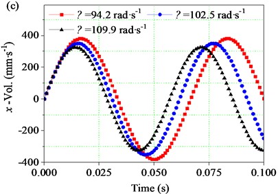
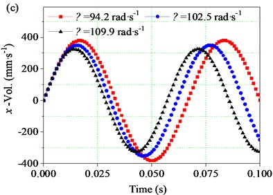
As can be seen from Fig. 15(a), in the vibration process of one period, the time-domain change curve of screen body displacement along the direction presents a sinusoidal change rule. When is 94.2 rad∙s-1, in one period (0-0.067 s), the displacement gradually increases from 0 to 4.04 mm, then gradually decreases to –4.04 mm, and then gradually increases to 0 (positive and negative signs indicate the displacement direction), and the displacement amplitude is 4.04 mm. When the rotational velocity increase to 102.05 rad∙s-1, the displacement amplitude reduces to 3.44 mm. When is further increased to 109.9 rad∙s-1, the displacement amplitude continues to decrease to 2.96 mm.
Fig. 15(b) shows the time-domain variation curve of screen body displacement along the direction. The phase Angle between the displacement curve and is 0°, and the corresponding displacement curve in the direction of the screen body also presents a sinusoidal change law. When the angular velocity increases from 94.2 to 102.05 rad∙s-1, the displacement amplitude of the screen body along the direction decreases from 4.07 mm to 3.45 mm. Similarly, when is further increased to 109.9 rad∙s-1, the displacement amplitude decreases to 2.97 mm.
Fig. 15(c) and Fig. 15(d) are the time-domain response curves of the screen body velocity along the and directions, which are derived from the first derivative of the displacement curves shown in Fig. 15(a) and Fig. 15(b) respectively. In the process of screen body vibration, the velocity of screen body shows harmonic fluctuation. As the angular velocity increases from 94.2 to 102.05 rad∙s-1, the velocity amplitude of the screen body along the direction decreases from 380.73 to 350.72 mm∙s-1, and as the rotational velocity continuously increases to 109.9 rad∙s-1, the velocity amplitude continuously decreases to 325.13 mm∙s-1. Similarly, when is increased from 94.2 to 109.9 rad∙s-1, the velocity amplitude of the screen body along the direction decreases from 383.02 to 326.56 mm∙s-1. Fig. 15(e) and 16(f) are the time-domain response curves , of the screen body acceleration along the and directions drawn according to the second derivative of the displacement curve. As increases from 94.2 to 109.9 rad∙s-1, the acceleration amplitude of the screen body in the direction slowly decreases from 35.86 to 35.72 m∙s-2, and the acceleration amplitude of the screen body in the direction slowly decreases from 36.08 to 35.89 m∙s-2.
It should be noted that when increases from 94.2 to 109.9 rad∙s-1, the displacement amplitude of the screen body along the direction decreases by 26.73 %, and the velocity and acceleration amplitude, decrease by 14.60 % and 0.39 %, respectively. Similarly, the displacement amplitude of the screen body along the direction decreases by 27.03 %. the velocity amplitude and acceleration amplitude , decrease by 14.74 % and 0.53 %, respectively. Therefore, when the angular velocity exceeds a certain range, the further increase of will reduce the vibration amplitude of the screen body, and the angular velocity should be controlled within a certain range.
5. Conclusions
1) The mechanical structure of the banana-type vibrating dewatering screen (BVDS) was described and the dynamic theoretical model was established. The vibration characteristics of the BVDS were studied through MATLAB/Simulink method. The dynamic characteristics and vibration behavior of the screen body were obtained. The trajectories of the screen body approximate straight line.
2) The dynamics parameters of the BVDS were tested by vibration test experiment. The dynamic characteristics including displacement, velocity and acceleration in and directions were compared with the theoretical results. The maximum error between experimental results and theoretical results is 6.58 %.
3) The vibration characteristics of the screen body at different angular velocities were obtained by theoretical analysis. The results show that with the increase of angular velocity, the screen body passes through the resonance region, the transition region and the working region successively. In the working region, with the increase of the angular velocity, the displacement amplitude of the screen and the velocity amplitude decrease gradually, and the acceleration amplitude is basically unchanged.
References
-
H. Jiang et al., “Optimization of the disequilibrium excitation rigid-flex elastic screening process and its application for coal beneficiation,” International Journal of Coal Preparation and Utilization, Vol. 42, No. 5, pp. 1460–1476, May 2022, https://doi.org/10.1080/19392699.2020.1725493
-
B.-C. Song, C.-S. Liu, L.-P. Peng, and J. Li, “Dynamic analysis of new type elastic screen surface with multi degree of freedom and experimental validation,” Journal of Central South University, Vol. 22, No. 4, pp. 1334–1341, Apr. 2015, https://doi.org/10.1007/s11771-015-2650-3
-
M. F. Eskibalci and M. F. Ozkan, “Comparison of conventional coagulation and electrocoagulation methods for dewatering of coal preparation plant,” Minerals Engineering, Vol. 122, pp. 106–112, Jun. 2018, https://doi.org/10.1016/j.mineng.2018.03.035
-
G. Chalavadi, R. K. Singh, M. Sharma, R. Singh, and A. Das, “Development of a generalized strategy for dry beneficiation of fine coal over a vibrating inclined deck,” International Journal of Coal Preparation and Utilization, Vol. 36, No. 1, pp. 10–27, Jan. 2016, https://doi.org/10.1080/19392699.2015.1048804
-
T. Bento Linhares and C. Bruno Santos Vimieiro, “Analysis of the dynamic forces acting on a vibrating screen and its support structure using a scale model,” Measurement, Vol. 176, p. 109179, May 2021, https://doi.org/10.1016/j.measurement.2021.109179
-
Z. Wang, C. Liu, J. Wu, H. Jiang, B. Song, and Y. Zhao, “A novel high-strength large vibrating screen with duplex statically indeterminate mesh beam structure,” Journal of Vibroengineering, Vol. 19, No. 8, pp. 5719–5734, Dec. 2017, https://doi.org/10.21595/jve.2017.18319
-
Z. F. Li, P. Y. Jia, K. Y. Li, X. Tong, and Z. H. Wu, “Study on screening performance and parameter optimization of vibrating-dewatering screen,” Advances in Mechanical Engineering, Vol. 13, No. 9, p. 15, Sep. 2021, https://doi.org/10.1177/16878140211046
-
V. P. Barbosa, A. L. Menezes, R. Gedraite, and C. H. Ataíde, “Vibration screening: A detailed study using image analysis techniques to characterize the bed behavior in solid-liquid separation,” Minerals Engineering, Vol. 154, p. 106383, Aug. 2020, https://doi.org/10.1016/j.mineng.2020.106383
-
P. W. Cleary, M. D. Sinnott, and R. D. Morrison, “Separation performance of double deck banana screens – Part 1: Flow and separation for different accelerations,” Minerals Engineering, Vol. 22, No. 14, pp. 1218–1229, Nov. 2009, https://doi.org/10.1016/j.mineng.2009.07.002
-
P. W. Cleary, M. D. Sinnott, and R. D. Morrison, “Separation performance of double deck banana screens – Part 2: Quantitative predictions,” Minerals Engineering, Vol. 22, No. 14, pp. 1230–1244, Nov. 2009, https://doi.org/10.1016/j.mineng.2009.07.001
-
K. Li, “Research and Parameter Optimization of dewatering screening performance of vibrating dewatering screen,” Fujian University of Technology, 2020.
-
H. Dündar, “Investigating the benefits of replacing hydrocyclones with high-frequency fine screens in closed grinding circuit by simulation,” Minerals Engineering, Vol. 148, p. 106212, Mar. 2020, https://doi.org/10.1016/j.mineng.2020.106212
-
H. Jiang et al., “Simultaneous multiple parameter optimization of variable-amplitude equal-thickness elastic screening of moist coal,” Powder Technology, Vol. 346, pp. 217–227, Mar. 2019, https://doi.org/10.1016/j.powtec.2019.01.052
-
A. Davoodi, G. Asbjörnsson, E. Hulthén, and M. Evertsson, “Application of the discrete element method to study the effects of stream characteristics on screening performance,” Minerals, Vol. 9, No. 12, p. 788, Dec. 2019, https://doi.org/10.3390/min9120788
-
A. Davoodi, M. Bengtsson, E. Hulthén, and C. M. Evertsson, “Effects of screen decks’ aperture shapes and materials on screening efficiency,” Minerals Engineering, Vol. 139, p. 105699, Aug. 2019, https://doi.org/10.1016/j.mineng.2019.01.026
-
H. Dong, X. Lu, and Q. Wang, “Research and development of a new type of dewatering screen,” Mining Machinery, Vol. 39, No. 8, pp. 97–100, 2011.
-
H. Dong, F. Zhou, and H. Yin, “Design Improvement analysis of Side plate beam exciter Dewatering screen exciter,” Mining Machinery, Vol. 40, No. 5, pp. 93–95, 2012.
-
Li Huaizhi, “Technical application of tailing dewatering screen in tailing dry discharge system,” Gansu Metallurgy, Vol. 36, No. 2, pp. 104–106, 2014.
-
Y. Li and Y. Zhang, “Application Practice of High efficiency and high frequency dewatering screen in tailings dry discharge treatment,” Gold, Vol. 37, No. 5, pp. 66–70, 2016.
-
K. An, J. Li, and P. Lu, “Application and research of dewatering shaker in foundation engineering mud treatment,” Sichuan Architecture, Vol. 38, No. 6, pp. 240–241, 2018.
-
P. Fang et al., “Synchronous state of unbalanced rotors in a three-dimensional space and far-resonance system,” (in English), Proceedings of the Institution of Mechanical Engineers, Part E: Journal of Process Mechanical Engineering, Vol. 234, No. 1, pp. 108–122, Nov. 2019, https://doi.org/10.1177/0954408919889416
-
Y.-Z. Jiang, K.-F. He, Y.-L. Dong, D.-L. Yang, and W. Sun, “Influence of load weight on dynamic response of vibrating screen,” Shock and Vibration, Vol. 2019, No. 1, Apr. 2019, https://doi.org/10.1155/2019/4232730
-
S. Baragetti and F. Villa, “A dynamic optimization theoretical method for heavy loaded vibrating screens,” Nonlinear Dynamics, Vol. 78, No. 1, pp. 609–627, Jun. 2014, https://doi.org/10.1007/s11071-014-1464-4
-
H. Jiang et al., “Kinematics of variable-amplitude screen and analysis of particle behavior during the process of coal screening,” Powder Technology, Vol. 306, pp. 88–95, Jan. 2017, https://doi.org/10.1016/j.powtec.2016.10.076
-
H. Li, C. Liu, E. Zhou, and L. Shen, “Research on dynamic and vibration behaviors of a flip-flow screen with crankshaft-link structure,” Journal of Vibroengineering, Vol. 24, No. 5, pp. 836–847, Aug. 2022.
About this article
This work is financially supported by the Doctoral Scientific Research Foundation of Suzhou University (2023BSK009, 2023BSK016), Key Research and Development Program Projects in Anhui Province (grant number 2023t070200), Key Project of Natural Science Research in Universities of Anhui Province (grant number 2022AH051380).
The datasets generated during and/or analyzed during the current study are available from the corresponding author on reasonable request.
Hongxi Li: conceptualization, methodology, writing-original draft, writing-review and editing, investigation. Enhui Zhou: resources, formal analysis, supervision. Haishen Jiang: validation, investigation. Ling Shen: writing-review and editing. Zixin Yin: software, funding. Zujin Jin: review and editing.
The authors declare that they have no conflict of interest.
