Abstract
A time-varying process with nonlinearity and time lag is the temperature control of pulsing vacuum steam sterilization. In order to achieve efficient and accurate control requirements, conventional PID temperature control algorithms sometimes display slow response speed, severe overshooting, unstable performance, and other challenges that ultimately affect the sterilizing effect. In order to find the ideal steam sterilization temperature control settings iteratively, this research used the PSO algorithm. Simulating and analyzing the system model is done simultaneously using fuzzy control of the PID parameter adaptive modification. According to the results, there is no overshooting and the response speed approach is faster. This paper presents an approach to fuzzy PID control based on the PSO optimization algorithm. As a result of fuzzy adaptive PID's high control accuracy and quick response time, the PID parameters are also continuously optimized utilizing the PSO approach for steam sterilization temperature control. For the purpose of doing simulation analysis, create and modify a system model. As evidenced by the results, this strategy has a reduced overshoot, a faster response time, and better stability. It may also successfully boost the control effect. Eventually, this method was applied to a self-tuning PID control experiment for sterilizer temperature control, and a relatively optimal control effect was obtained.
Highlights
- Self-tuning fuzzy PID control system based on IPSO.
- Temperature control of pulse vacuum steam sterilizer.
- Sterilizer hardware structure and embedded software state machine.
1. Introduction
Disinfection and sterilization are highly valued by people as illnesses like SARS and influenza spread around the world. By denaturizing all bacteria’ proteins and enzymes at high temperatures, sterilization technology kills the microbes [1-2]. In order to fully sterilize objects, the pulsating vacuum sterilizer employs saturated pressure steam as the sterilizing medium. It does this by releasing latent heat from the steam's high pressure and high heat. One of the most significant functions of contemporary sterilization equipment is effective sterilization, which is a rather sophisticated sterilization method utilized in big and medium-sized hospitals, pharmaceutical companies, and scientific research.
German MELAG, Swedish GETINGE, Italian JUST, Austrian Bmax, and Israeli Tuttnauer are some of the top brands of sterilizing goods [3-6]. Both the high cost and great technical performance of these goods are well recognized. High-performance and high-precision medical sterilizers are becoming increasingly important as the need for sanitizing medical equipment grows.
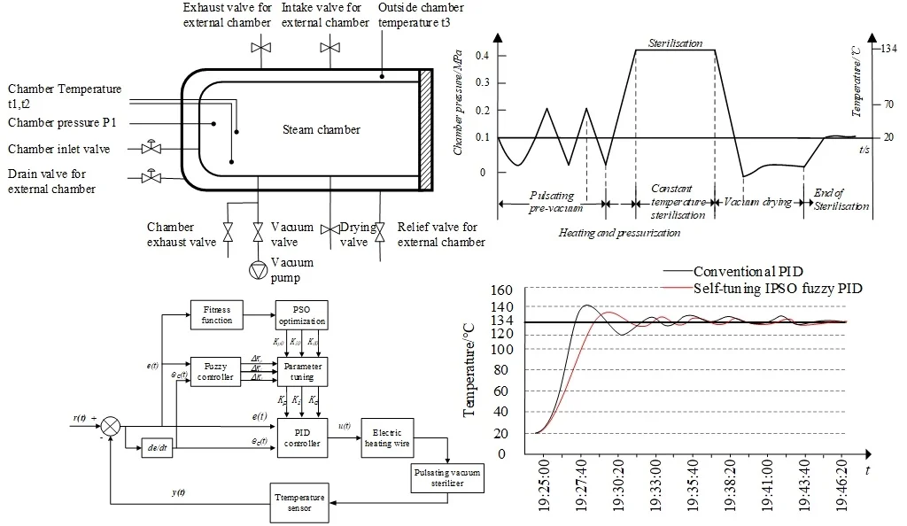
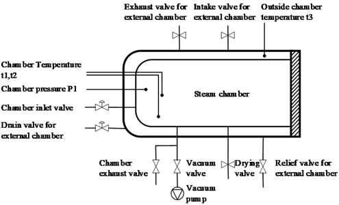
A steam generator, vacuum pump, water supply pump, sterilizing chamber, and other parts for insulation, temperature control, and measurement make up the steam sterilizer’s major parts. Internal to the chamber are pressure and temperature sensors. As seen in Fig. 1, the steam sterilizer’s construction.
The steam sterilizer utilizes a mechanical forced pulsating vacuum degassing method [7]. This involves repeated vacuuming and injection of high temperature steam to create a certain level of vacuum in the sterilization chamber. Saturated steam is then injected to reach the desired pressure and temperature for effective sterilization.
Fig. 1Structural diagram of the pulse vacuum steam sterilizer
Four steps make up a comprehensive vacuum steam sterilization process, as required by sterilization process requirements: pulsing pre-vacuum, temperature and pressure adjustment, constant temperature sterilization, and vacuum drying. The pressure variations throughout each stage of the sterilizing process are depicted in Fig. 2.
Fig. 2Graphical representation of a steam sterilization cycle
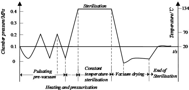
Pulsating Pre-vacuum Stage: three alternates of evacuation and steam delivery occur. The steam generator’s valve is opened to allow saturated water vapor to enter the chamber, raising the pressure inside, each time the pre-vacuum achieves the predetermined pressure and time parameters. Until a parameter value just over atmospheric pressure is obtained, this process is repeated.
Heating and Pressurization Phase: the temperature and pressure within the chamber will increase as steam is continuously introduced, eventually reaching 2.1 bar and 134 °C.
Sterilization Stage: for 20 minutes, the temperature and pressure must remain above 134 °C and 2.1 bar, respectively. A negative pressure is produced in the sterilizer chamber by regulating the heater and the vacuum pump. This enables the steam to enter the chamber fast and sanitize the interior of the object.
Drying Stage: the drying stage starts when the sterilization step is finished and the pressure is released. The product is dried rapidly using vacuum to assure the drying effect, and the chamber is simultaneously vented and pressure compensated at the end of the drying stage.
High-temperature, high-pressure saturated water vapor is used for sterilization in the pulsing vacuum pressure steam sterilization control system. Significant hysteresis, significant inertia, and one-way temperature and pressure increases are features of the steam pressure and temperature control. Among these, the sterilization room's heating and constant temperature sterilization stages are crucial to the overall process. The interior of the sterilized items may not meet the requirements for sterilization if the temperature rises too quickly during the work. In addition, even though the temperature of the superheated steam is high, it cannot condense into water when it comes into contact with sterilized items and cannot release latent heat, which is bad for sterilization and leads to the wet pack problem.
The sterilizer controlling parameters are heated by the resistance wire, while the sterilizer's cooling process is based on the ambient natural cooling process. Thus, it is difficult to develop an accurate model using mathematical techniques and to achieve an effective control effect using typical control methods. Conventional PID controllers have trouble controlling uncertain models and nonlinear time-varying systems [8]. As a result of the extensive analysis of pulsating vacuum sterilization systems, intelligent controllers are beginning to become a prominent area of research.
Pany, C. et al. [9] discuss the use of time series mathematical model simulations and output generations for river flow prediction, which provides more accurate and reliable prediction and decision-making support for flood early warning, drought prevention water resource management, and provides a reference for steam prediction control based on neural network control.
Fuzzy control technology can mimic human thought processes and make decisions based on fuzzy [10], uncertain data in order to successfully establish control. PID control and fuzzy control work together to continuously modify and adjust the PID parameters. This effectively avoids the influence of parameter setting on the control process and control results, fully utilizes the benefits of these two algorithms, and enhances the system’s control performance.
Fuzzy PID control is created by combining the fuzzy algorithm – which is introduced in the work – with traditional PID control. Lian L [11] proposed a fuzzy PID controller and applied it to the main steam temperature control, which achieved good control effect, but the fuzzy rules could not be changed after being determined by the expert experience, resulting in poor controller performance.
PID self-tuning is a tuning strategy that computes PID parameters automatically by identifying the characteristics of the process that has to be managed. However, fine-tuning the PID controller's parameters takes a lot of time and energy [12-13]. Liu [14] developed a self-adjusting fuzzy PID algorithm capable of adapting to intricate variable temperature control systems.
In 1995, R. C. Eberhart and J. Kennedy proposed a global optimization algorithm based on the evolution of population intelligence-Particle Swarm Optimization (PSO) [15], which has the advantages of simple implementation, fast convergence, and high solution quality [16], and has achieved excellent results in the optimal solution of objectives in the fields of scientific computation and engineering applications.
In [17], the PSO algorithm optimizes the fuzzy self-tuning PID controller parameters of the superheated steam temperature control system. However, it is prone to local optimization [18], which negatively impacts algorithm performance and leads to optimized parameters that are not precise.
This work presents an improved particle swarm optimization (IPSO) based self-tuning fuzzy PID temperature control approach to address this issue. With the fitness function of PSO being the complete evaluation index ITAE (Integral of Time and Absolute Error), the fuzzy PID controller performance is enhanced by optimizing key settings. Second, the intelligent PID algorithm was effectively used to the sterilization chamber's steam temperature management, yielding positive outcomes. A self-tuning fuzzy PID controller was utilized to regulate the temperature of the pulse vacuum sterilizer in real time.
2. PSO optimized fuzzy PID sterilizer temperature control algorithm design
This study uses the PID controller design to regulate the sterilizer chamber temperature. The algorithm used for PID control is:
where is the difference between the current output value and the setpoint, is the controller output function at time . is the proportional coefficient, is the integral time constant, is the differential time constant. The controller adjusts the gain values of these three units.
The proportional coefficient affects the strength of the control action [19]. If is increased appropriately, the control effect can be strengthened, the system response speed can be improved, the response time can be shortened and the system static error can be reduced [20]. However, if is too large, the stability of the system will deteriorate. The function of the integral coefficient is to reduce the system residual error. If is too large, the response speed of the system will decrease, the overshoot of the system will increase and the stability of the system will deteriorate. The function of the differential coefficient is to reduce the overshoot of the system, overcome oscillations and stabilise the system.
Usually, the tuning of the PID controller parameters consists of tuning these three parameters or some of them [21]. In the field of industrial control, common tuning methods include critical proportional method and damping curve method, but these methods are less effective for highly coupled and highly nonlinear systems [22-23]. With the development of computer technology and intelligent control method research, more and more intelligent control methods are being introduced into PID control to determine parameters, which improves the control effect of the controller to a certain extent.
The fuzzy PID control system is a cascade control system formed by combining fuzzy control and ordinary PID control. Its principle is that the controller first processes the exact amount of deviation and deviation change rate through fuzzy processing, and then uses the membership function to make and fall into the corresponding discourse domain and are given fuzzy language values, and then fuzzy reasoning is performed through fuzzy rules. Finally, the obtained results are defuzzified through the scale factor to obtain , , , correcting the three characteristic parameters , , of PID, that is:
where , , represent the PID characteristic parameters before updating, , , represent the updated PID characteristic parameters.
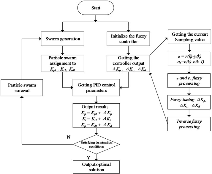
Fuzzy PID adaptively tunes the parameters during the control process, but it has problems such as being limited by human experience, unable to satisfy on-line tuning, and slow response speed. In order to quickly realize the parameter tuning of the fuzzy PID algorithm for sterilizer temperature control, and to meet the requirements of accuracy and small overshoot, this paper proposes a PSO-optimized fuzzy self-tuning PID algorithm. The structure of the proposed control system is shown in Fig. 3.
Fig. 3Self-tuning fuzzy PID control system based on IPSO
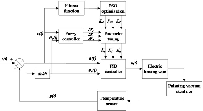
First, the PSO algorithm optimizes the initial values of the fuzzy PID control parameters , , , the fuzzy control adjusts the PID control parameters, and the adjustment amount is , , , and calculates the fitness value through the fitness function to judge whether the PID parameters are optimal or not, and keeps adjusting the parameters to continuously reduce the fitness value so as to find the most suitable set of values to achieve the desired control effect.
2.1. Fuzzy Pid controller design
Fuzzy set theory is applied to establish the binary continuous function relationship between the parameters , , and the absolute value of the system error and the absolute value of the error change rate . The fuzzy controller is used to self-adjust the PID parameters according to different and online, which is the core of the control system design.
The change of steam temperature in the sterilization chamber is relatively slow, that is, the change of error is relatively small. The deviation and the deviation change rate between the actual value of the sterilization chamber temperature and the set value are used as input variables of the fuzzy controller, and the three parameters of the PID are used to incrementally correct the value proportional coefficient and integral coefficient and differential coefficient are used as the controller output, and the continuous domain is set to (–4-4) ℃.
The quantized discrete domain is: .
In order to balance the control accuracy and complexity of the system, the fuzzy domain of input and output is set to seven regions {NB, NM, NS, Z, PS, PM, PB}, which respectively correspond to {negative large, negative medium, negative small, zero, just small, middle, big}.
Among them, the actual sampling and are fuzzified to obtain E and EC. If data larger than the boundary value is encountered during the temperature control process, it will be directly taken as the boundary value. and are the fuzzy quantization factors, and int is rounded. All:
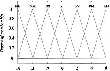
Considering the simplicity and practicability of the algorithm, the triangular membership function is used as the fuzzy membership function of the input and output variables, as shown in the membership function curves of E and EC in Fig. 4, which are also the membership function graphs of , and .
Fig. 4The membership functions for E or EC
2.2. Fuzzy inference
Sterilizer temperature Fuzzy control is implemented based on fuzzy control rules. Fuzzy inference employs a dual-input, single-output approach, with control rules formulated in the following inference languages of “if and then”.
According to the characteristics of the influence of sterilizer, , on system output, the fuzzy rules for the positive and negative values of and should be formulated according to the following principles:
(1) When is large, should be a larger value in order to speed up the response speed of the system and avoid the differential saturation beyond the control range due to the instantaneous increase of deviation; To reduce the amount of overshoot, should be as small as possible, and should be a smaller value.
(2) When is at a medium size, in order to make the system response have a small overshoot, should be set to a small value, and should be set to a moderate value.
(3) When is small, the values of and are larger to ensure that the system has better stability. At the same time, in order to avoid system oscillation near the set value, it is judged that if is large, the value is small, and usually the value is moderate.
According to the above fuzzy rules, the fuzzy control rules table is shown in Table 1.
Table 1Fuzzy control rule table
NB | NM | NS | Z | PS | PM | PB | |
NB | NB/NB/NB | PB/NB/PS | PM/NM/NS | PM/NM/Z | PS/NS/Z | PS/Z/PB | Z/Z/PB |
NM | NM/NM/NM | PB/NB/NS | PM/NM/Z | PS/NM/NS | Z/NS/Z | Z/Z/NS | Z/Z/PM |
NS | NS/NS/NS | PM/NM/NB | PM/NS/NM | PS/NS/NS | Z/Z/Z | NS/PS/PS | NM/PS/PM |
Z | Z/Z/Z | PM/NM/NM | PS/NS/NM | Z/PB/PS | NS/PS/Z | PM/Z/PB | NM/PM/PM |
PS | PS/PS/PS | Z/NS/NM | Z/Z/PB | PB/PB/PS | PB/PM/PM | PM/Z/PB | NM/PB/PS |
PM | PS/Z/PM | Z/Z/NS | Z/Z/NS | PB/PB/PS | PB/PB/PM | PM/PS/PB | NB/PB/PS |
PB | PB/PB/PB | NS/Z/Z | NS/PS/Z | PM/PB/Z | PM/PM/PM | PS/PS/PS | NB/PB/PB |
In the process of online operation, the fuzzy PID parameter self-tuning control system completes the online calibration of PID parameters by processing the results of the fuzzy logic rules, looking up the table and calculating a series of processes, which meets the different requirements of the system for controller parameters under different time E and EC.
2.3. Obtaining and de-blurring fuzzy relation
Define fuzzy subsets , and respectively on , and . The fuzzy control rule is described as the fuzzy relationship R from to :
According to the theory of fuzzy mathematics, the output of the fuzzy controller can be obtained by the fuzzy synthesis rule:
The fuzzy output cannot be directly used to control the controlled object, so it is necessary to de-fuzzy processing. The weighted average method is to multiply the membership degree of each fuzzy set with the center of gravity of the fuzzy set and then divide by the sum of each membership degree. This method includes the role of all elements in the output domain, and highlights the main information through the weighted coefficient, so the output quantity obtained is relatively accurate. The calculation is as follows:
where, is the final clear output value, is the number of elements in the output fuzzy theory domain, is the value of the th element in the output fuzzy theory domain, and is the membership degree of the i th element in the output fuzzy theory domain.
The sterilization controller adopts intelligent fuzzy PID control. The specific realization is that after processing the sampled temperature by CPU, the corresponding error and error change rate are obtained, and then the control quantity is obtained by querying the fuzzy decision table, and the control output is obtained by calculation, so as to control the opening of the regulating valve and change the amount of steam entering the sterilization chamber. Achieve the requirement of stable control temperature at a given value.
In practice, the temperature is far from reaching the given requirements of the temperature, in order to ensure that the maximum speed of warming, regulating valve opening to the maximum; close to the given requirements of the temperature before the use of intelligent fuzzy PID control.
2.4. PSO algorithm improvement
Let's assume there are particles within the -dimensional search space, with the position of the ith particle is denoted as , the velocity is , the individual polarity , and the global polarity . It is through individual learning and group experience that the particles decide the next movement, and for the st iteration, each particle evolves according to the following equation:
where , is the total number of particles in the population, , is the dimension of the solution space; is the inertia weights, and the acceleration factors, and , regulate the maximum step of the flight in the direction of and , respectively.
As the traditional PSO fuzzy PID controller is easy to fall into the local optimum, resulting in slow convergence speed. To solve these problems, the weight coefficients and inertia factors of PSO need to be improved to effectively solve the performance problems of the traditional fuzzy PID controller and the pain point of slow convergence speed of the system.
2.4.1. Improvements to the adaptive component
The PSO algorithm’s velocity update formula contains three parameters: inertia weights and learning factors and . A proper averages the global and local optimality search. A large in the early stage can quickly reach the neighborhood of the optimal value, and a small in the late stage can reduce the speed of the particles so that they can perform a detailed search locally at the optimal value. Therefore, a way of linearly decreasing the value of can be adopted:
where , are the initial inertia weights and the inertia weights when iterating to the maximum number of times , respectively, and is the current number of iterations.
The functions of the learning factors and are self-summary and learning from fine particles respectively. Too large or too small values of both are not conducive to the execution of the algorithm, so it is extremely important to set appropriate values in the optimization. In this study, a factor gradient method is proposed:
where is the current iteration number, is the maximum iteration number.
The improved particle velocity update equation is:
By improving the velocity formula, the particles are made adaptive and updated with iterations, which improves the strength of the global optimization search. However, this adaptive capability of PSO also has shortcomings, such as inaccurate tracking, slow convergence, and a tendency to mature prematurely.
2.4.2. Improvements in the migration component
Since the diversity of the particles in the PSO algorithm concerns whether or not it converges early into the local extremes. Where the particles will draw on the values of and at each iteration, which reduces their diversity too quickly, which in turn leads to poor accuracy [16]. Therefore, n particles are divided into s populations, and adaptivity is applied to make a judgment on the population polytopes using :
where is the number of iterations, is the value of particle adaptation in generation and 1.
2.4.3. Improvements of PSO algorithm to optimize fuzzy PID control process
ITAE criterion is chosen as the algorithm fitness function in the design of the improved PSO algorithm:
where is the total time, is the temperature deviation. That is, the integral of the product of the absolute value of time and temperature deviation as the degree of adaptation, the smaller its value, the better. ITAE performance indicators can comprehensively measure the level of excellence of the sterilizer temperature control system, which is reflected in steady-state error, overshoot amount, control time and other indicators.
The process of the optimization of the initial parameters of the Fuzzy PID by the improvement of the PSO algorithm is shown in Fig. 5.
Fig. 5Flow chart of the fuzzy PID algorithm based on IPSO
Step 1. Initialization of the particle swarm: the population size of the particles is chosen as 50 particles, the dimension is 3 dimensions, the inertia weight is usually chosen between [0.9, 1.2], and this time the value of is chosen as 0.9, the learning factor 2, the value of the speed of the search space is in the range [–1, 1], and the maximum number of iterations n is taken as 100 times.
Step 2. Selection of fitness function : that is, to determine the criteria for iterative optimisation of the algorithm, based on the value of fitness to determine the degree of optimisation of particles in the optimisation process, and the degree of current particles to initialise the individual optimal and the group optimal . In this paper, we choose the absolute value of the error of Eq. (9) of the integral of time as a performance indicator.
Step 3. Cyclic iterative optimization process, each iteration of the process that the particle position and velocity information is updated, after the process, the optimal value of the three dimensions of the particle population is assigned to , , , run the sterilizer temperature control system, obtain the fitness value of all the particles to be compared to select the optimal fitness value of the individual and the optimal fitness value of the population.
Step 4. Performs particle swarm velocity and position updates.
Step 5. Judge the end condition of the optimization iteration. If the particle reaches the optimal solution or completes the number of iterations, the algorithm ends and outputs the optimal solution, otherwise reassign the updated particle swarms to , , and jump to step 3 to continue the algorithm.
3. Simulating and experimentally validating a fuzzy PID controller for PSO optimization
3.1. Step response experiment
Experimental methodologies are used to model the system of pulsating vacuum sterilization control:
To evaluate the effectiveness of the IPSO optimization algorithm on the temperature control system of a pulsed vacuum sterilizer, three Simulink simulation models were developed for traditional PID control, fuzzy PID control, and an improved particle swarm optimization fuzzy PID algorithm. A comparison of these models is presented in the Fig. 6.
Fig. 6Model Simulink of control system for pulsation vacuum sterilizer
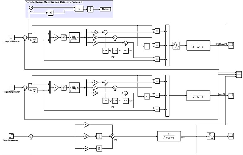
The Fuzzy Logic Toolbox in MATLAB is used to design the fuzzy controller. The IPSO algorithm implementation begins with the development of the Matlab IPSO optimization program, as well as the program that connects the particle swarm optimization program with the Simulink simulation model and the PID model graph for IPSO.
The PSO algorithm is implemented by creating a program in the PSO_PID.m file. The initial values of the fuzzy PID control parameters are optimized by executing the program, passing the values of the generated particle swarm into the simulation model through the sim() function, and then reading the fitness values calculated by the fitness function.
Fig. 7 shows the three step response curves of the sterilizer temperature control system under traditional PID control, fuzzy PID control and PSO optimized fuzzy self-tuning PID control.
It can be seen that the traditional PID control system response speed is slow, the overshooting amount is large, the time to reach steady state is long, accompanied by a slight oscillation phenomenon; fuzzy PID controller in the stability and overshooting amount is better than the PID control, due to the use of the expert experience to adjust the weighting factor and has a blindness, can't carry out the parameter tracking adjustment, the control speed is slow.
Fig. 7The tracking curves of the three control methods under disturbance
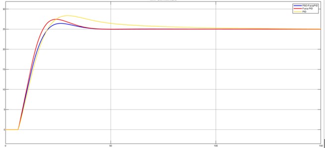
The PSO fuzzy PID control is used to provide the fastest response, the smallest amount of overshooting, the shortest time for the system to reach the steady state, and the system is free of oscillations. In summary, when the sterilizer temperature control, the use of PSO fuzzy PID control algorithm using PSO optimization algorithm for steam sterilization temperature control parameters iterative optimization, while through the fuzzy control of the PID parameters adaptive correction, response speed, overshooting amount, inhibit oscillations and time to reach the steady state, etc. are better than the ordinary PID control and fuzzy PID control.
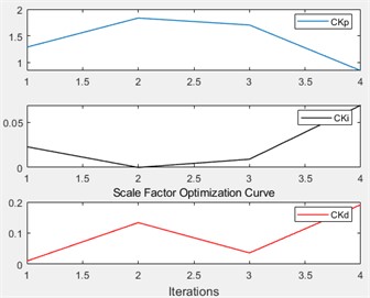
By using PSO algorithm to optimize the initial parameters of the fuzzy PID controller, the temperature control system is controlled. The control results are shown in Figs. 8-9. The particle swarm can output the optimal solution after iterating 4 times, and its optimal fitness value is 2659.
The initial value optimization results of the particle swarm algorithm for the fuzzy PID control parameters , and are 1.3268, 0.06139, and 0.1851 respectively.
Fig. 8ITAE fitness iterative optimization curve
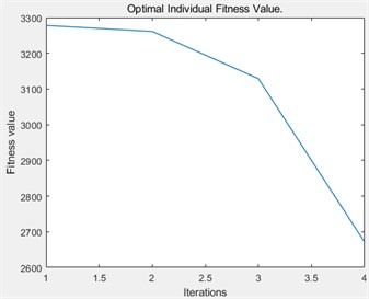
Fig. 9Effect diagram of online parameter setting in PID
3.2. Disturbance experiments
To verify the control effect of different control methods, it is necessary to keep the parameters of each controller unchanged. A 20 % step perturbation signal should be added when the system is simulated to be stable at certain time. At this time, the performance indicators of different control methods under normal conditions are shown in Table 2.
Table 2Performance indicators of different control methods under normal conditions
Methods of control | Adjusting time (s) | Overshoot (%) |
PID | 1360 | 25.3 |
Fuzzy-PID | 1190 | 19.0 |
IPSO-Fuzzy-PID | 549 | 4.2 |
As can be seen from Table 2, PID and Fuzzy-PID have poor ability to suppress interference after disturbance is added to the system, resulting in large oscillation of the system. The IPSO-Fuzzy-PID has a strong ability to restrain the interference, effectively restrain the fluctuation of the main steam temperature on the disturbed side, and make the system output recover to the stable state smoothly and quickly, and improve the adaptive ability of the main steam temperature control system.
3.3. System robustness analysis
In order to further validate the robustness of different control methods, the gain of the transfer function for the controlled object in the inert zone was increased by 20 %, while maintaining unchanged parameters for each controller. This adjustment is made due to variations in the mathematical model of the controlled object within the sterilizer steam temperature control system as a result of changes in cavity temperature.
Table 3Performance indicators of different control methods when gain increases
Methods of control | Adjusting time (s) | Overshoot (%) |
PID | 1436 | 35.7 |
Fuzzy-PID | 1019 | 27.1 |
IPSO-Fuzzy-PID | 531 | 6.4 |
The performance indicators of different control methods when gain increases are shown in Table 3. It can be seen that the IPSO-Fuzzy-PID still maintains high control quality under the condition of 20 % gain increase, while the regulation time of the PID increases by 19% compared with that of the model matching and produces serious overshooting, which makes the control effect worse.
3.4. Experimental verification
3.4.1. Hardware system block diagram
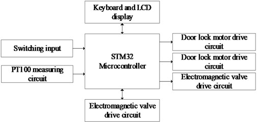
The hardware system block diagram of the pulsating vacuum high-temperature steam sterilizer control system is illustrated in Fig. 10. The system comprises the main control circuit of the STM32 microcontroller, a platinum resistance temperature measurement circuit, a switch input circuit, a door lock motor control circuit, solenoid valve drive circuits for water inlet, drainage, and exhaust, a heating coil control circuit, a real-time clock circuit, a keyboard and an LCD display circuit, among others.
The whole control system is based on high-speed STM32 microcontroller as the core, real-time sampling of the temperature in the chamber of the sterilizer, and after self-Tuning Fuzzy PID and IPSO algorithm operation, it generates a PWM signal with a period of 0.5 s and an adjustable duty cycle to control the heating ring power supply on/off, so as to make the temperature inside the chamber of the sterilizer at 121 ℃ and maintain it for 20 mins or 134 ℃ and maintain it for 4mins in order to achieve the effect of sterilization.
Fig. 10Overall hardware structure of the system
3.4.2. Temperature measurement circuit
The high-precision temperature measurement circuit, featuring a three-wire platinum resistor and a constant current source as illustrated in Fig. 11, primarily comprises a constant current source circuit and an A/D conversion circuit. This includes a constant current source circuit with a dual voltage reference, an operational amplifier, and a transistor, a CS1237 ADC, a three-wire platinum resistor interface circuit, and an SPI output interface circuit. The platinum resistor temperature measurement circuit converts the temperature signal into a voltage signal, which is then sampled and computed by the ADC chip to determine the temperature.
Fig. 11Temperature measurement circuit
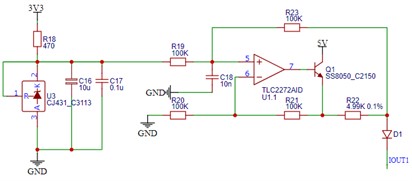
a) Constant current source circuit
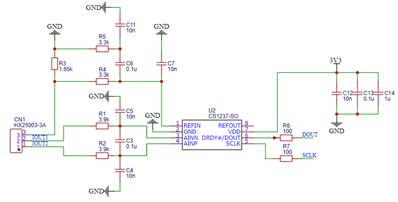
b) A/D conversion circuit
The CJ431 chip within the constant current source circuit serves as an integrated circuit for generating a reference voltage. The CJ431 ensures that the input voltage to the input resistor, connected to the non-inverting terminal of the TLC2272 operational amplifier, remains constant at 2.5 V.
Based on the circuit connection, it is evident that the operational amplifier introduces negative feedback. Drawing from the characteristics of an ideal operational amplifier and the principles of virtual short and virtual open, we can deduce that:
Hence, the current passing through the 4.99 K sampling resistor is:
By selecting a precision sampling resistor with low temperature drift and high accuracy, the entire system can achieve high-precision temperature measurement.
Owing to the adoption of a constant current driving method in the temperature measurement circuit, the dual constant current sources ensure a stable current, reducing susceptibility to fluctuations within the circuit. This addresses the issues of low measurement accuracy and sensitivity to temperature drift inherent in conventional temperature measurement systems.
The CS1237 conversion circuit is employed to convert minute voltage signals into digital signals with 24-bit precision. The sensor utilizes a platinum resistor, nominally 100 Ω at 0 ℃. The three-wire system eliminates measurement errors due to lead resistance and employs a constant current source for signal conditioning and compensation, thereby enhancing signal stability.
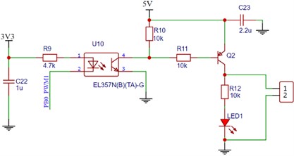
3.4.3. Heating coil control circuit
As shown in Fig. 12, the drive circuit of the sterilizer heating coil mainly uses solid-state relays, optocouplers and transistors as the devices of the control circuit, and the microcontroller samples the temperature of the sterilizer cavity in real time, and generates the solenoid valve drive signal to control the heating after IPSO optimization and fuzzy PID algorithm operation.
Fig. 12Heating coil control circuit
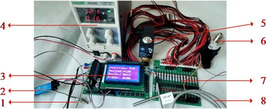
3.4.4. PID self-tuning experimental platform for pulsating vacuum sterilizers
The experimental platform for temperature control PID self-tuning, as illustrated in Fig. 13. The sterilizer uses a three-wire platinum resistance PT100 temperature sensor to get the real-time temperature value in the sterilizer cavity, and the temperature measurement accuracy is ±0.1 ℃. Through the CS1237 ADC will be collected analog signals converted into digital signals, and then through the STM32 microcontroller will be collected temperature and set the temperature deviation value according to the control algorithm to get the value of the duty cycle of the PWM signal to drive the H-bridge circuit, control the sterilizer electric filament heating module drive circuit work to ensure a certain degree of precision at the same time to achieve a constant temperature and the purpose of sterilization. The purpose of constant temperature and sterilization is achieved while ensuring a certain degree of precision.
Fig. 13PID self-tuning experimental platform for pulsating vacuum sterilizers: 1 – resistance wire; 2 – ST-LINK STM32 emulator programmer; 3 – sterilizer temperature control panel; 4 – control system power supply; 5 – electromagnetic valve; 6 – pressure sensor; 7 – signal expansion board; 8 – PT100 temperature sensor
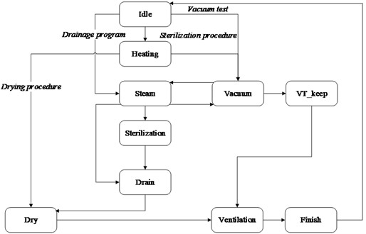
3.4.5. State machine for embedded software architecture design of sterilizers
The state machine in the embedded software architecture design for the sterilizer primarily comprises 10 states: preparation, preheating, pulsating vacuum, heating sterilization, exhaust, drying, and sterility, among others. As illustrated in Fig. 14, the sterilization process begins with the system executing vacuum pulsation according to the preset values. Following this, the control system introduces saturated steam, elevating both temperature and pressure. Once the inner chamber attains the designated temperature, the process transitions to a constant temperature sterilization phase employing intelligent fuzzy PID temperature control. Upon completion of sterilization, the system proceeds to the exhaust and drying phase; upon successful drying, the primary program concludes.
Fig. 14Embedded software main state machine for sterilizer
The IPSO optimized fuzzy self-tuning PID algorithm of the STM32 single-chip microcomputer was written, and the single-chip microcomputer was programmed. At the same time, the self-tuning user interface program of the host computer was opened to debug the temperature control system of the sterilizer control board with load, and the PID self-tuning process data curve of the pulsating vacuum sterilizer was obtained, as shown in Fig. 15.
Fig. 15The data curve of self-tuning for Pulsating vacuum sterilizer
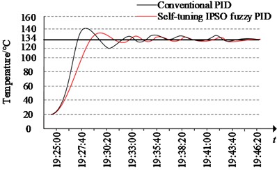
The pulsation vacuum sterilizer is set to a temperature of 134 ℃, with automatic tuning of the PID parameters. Once the self-tuning process concludes, the variations from this process are retrieved from the database and graphically depicted. It is evident that the final temperature is maintained at 135 ℃, with the curve attaining the target temperature and stabilizing in just 24 seconds.
Using the conventional PID algorithm, the temperature initially rises from 20.25 ℃ to the target temperature of 134 ℃ in 140 seconds. The maximum overshoot occurs at 19:28:00, with an overshoot of 4.92 ℃. At 19:29:20, the temperature drops to 134 ℃, but the system is not stable, and the temperature continues to drop. At 19:30:20, the temperature reaches 120 ℃ before continuing to rise. Eventually, the error continually reduces in fluctuations, and by 19:33:00, the temperature stabilizes at 134 ℃±0.3 ℃, and by 19:44:00, it stabilizes at 134 ℃±0.2 ℃.
Under the same experimental conditions, the system was controlled using a self-tuning fuzzy PSO PID algorithm. Compared to conventional PID control systems, the temperature initially rose from 20.21 ℃ to the target temperature of 134 ℃ in 240 seconds, with an overshoot of only 3.4 ℃. Subsequently, the temperature continued to decline, but the undershoot was significantly smaller than that of conventional PID control, with the lowest temperature recorded at 130 ℃ at 19:32:20. Ultimately, the system reached a stable state, stabilizing at 134 ℃±0.23 ℃ at 19:31:40 and at 134 ℃±0.1 ℃ at 19:42:10.
4. Conclusions
This paper proposes a fuzzy PID self-tuning control strategy based on the IPSO algorithm. The PSO algorithm iteratively optimizes the temperature control parameters for steam sterilization, while the PID parameters are adaptively refined through fuzzy control. A system model simulation analysis was conducted, revealing that the method offers a faster response speed, zero overshoot, and enhanced robustness. Subsequently, the algorithm was implemented in a self-tuning PID control experiment for the temperature control of a sterilizer, achieving self-tuning of the PID parameters, improved dynamic and static performance of the control system, and enhanced precision in temperature control. Experimental results demonstrate that, when using the self-tuning fuzzy PID algorithm and setting the sterilization temperature at 134 °C, the system achieves an overshoot of only 0.78 °C, a reduction of 0.5 °C from conventional PID; the steady-state temperature remains within 143±0.2 °C, a 65 % improvement over conventional PID, achieving an ideal control effect.
While some expected results of this study have been obtained, there are still certain problems that require investigation and treatment. (1) Fuzzy PID control offers high precision and rapid adjustment, though with a significant overshoot. Alternatively, artificial neural network control, known for its self-learning capabilities, is also a viable option. (2) The sterilization temperature control system developed in this study fulfills the current fundamental requirements for sterilization control, yet there is a need to enhance the communication rate to attain stronger stability. Leveraging TCP/IP protocol functionality enhances its role in remote maintenance, alarming, and video surveillance. The human-machine interface is continuously refined, rendering the control of pulsation vacuum sterilizers more intelligent and contemporary. (3) In industrial applications, data security is highly sensitive, and the security and privacy protection for sterilizer temperature control data presents significant challenges.
Consequently, the future trajectory for the pulsation vacuum sterilizer control system is towards intelligence and modernization, striving for excellence in enhancing human health and wellness.
References
-
L. Boehler, M. Daniol, R. Sroka, D. Osinski, and A. Keller, “Sensors in the autoclave-modelling and implementation of the IoT steam sterilization procedure counter,” Sensors, Vol. 21, No. 2, p. 510, Jan. 2021, https://doi.org/10.3390/s21020510
-
S. Banerjee, S. Raghunathan, S. Banerjee, and B. Bandyopadhyay, “Portable sterilizer with microbe content detection device,” Bulletin of the National Research Centre, Vol. 45, No. 1, pp. 1–5, Feb. 2021, https://doi.org/10.1186/s42269-021-00496-z
-
D. Morganstern and J. Miller, “State-of-the-art equipment for sterilization and biocontainment since 1925,” Lab Animal, Vol. 44, No. 11, pp. 455–455, Oct. 2015, https://doi.org/10.1038/laban.899
-
B. Bharti, H. Li, Z. Ren, R. Zhu, and Z. Zhu, “Recent advances in sterilization and disinfection technology: A review,” Chemosphere, Vol. 308, p. 136404, Dec. 2022, https://doi.org/10.1016/j.chemosphere.2022.136404
-
C. A. Wallace, “New developments in disinfection and sterilization,” American Journal of Infection Control, Vol. 44, No. 5, pp. e23–e27, May 2016, https://doi.org/10.1016/j.ajic.2016.02.022
-
A. Sakudo, R. Yamashiro, and T. Onodera, “Recent advances in prion inactivation by plasma sterilizer,” International Journal of Molecular Sciences, Vol. 23, No. 18, p. 10241, Sep. 2022, https://doi.org/10.3390/ijms231810241
-
C. Y. Lee, J. H. Kim, J. W. Bae, and Y. S. Chai, “Erratum: “development of the high temperature fretting wear simulator for steam generator”,” International Journal of Modern Physics B, Vol. 25, No. 20, pp. 2789–2789, Aug. 2011, https://doi.org/10.1142/s0217979211058997
-
J. Chen, Q. Lu, J. Bai, X. Xu, Y. Yao, and W. Fang, “A Temperature control method for microaccelerometer chips based on genetic algorithm and fuzzy PID control,” Micromachines, Vol. 12, No. 12, p. 1511, Dec. 2021, https://doi.org/10.3390/mi12121511
-
C. Pany, U. K. Tripathy, and L. Misra, “Application of artificial neural network and autoregressive model in stream flow forecasting,” Journal of Indian Water Works Association, Vol. 33, No. 1, pp. 61–68, 2001.
-
Z. Wu, T. He, D. Li, Y. Xue, L. Sun, and L. Sun, “Superheated steam temperature control based on modified active disturbance rejection control,” Control Engineering Practice, Vol. 83, pp. 83–97, Feb. 2019, https://doi.org/10.1016/j.conengprac.2018.09.027
-
Lian Lian, “Main steam temperature control based on variable universe fuzzy dynamic matrix control,” Thermal Engineering, Vol. 69, No. 10, pp. 763–778, Oct. 2022, https://doi.org/10.1134/s0040601522100044
-
H. Li, Y. Hui, J. Ma, Q. Wang, Y. Zhou, and H. Wang, “Research on variable universe fuzzy multi-parameter self-tuning PID control of bridge crane,” Applied Sciences, Vol. 13, No. 8, p. 4830, Apr. 2023, https://doi.org/10.3390/app13084830
-
X. Cheng et al., “A fuzzy adaptive PID control method for novel designed rail grinding equipment,” IEEE Access, Vol. 11, pp. 118–124, Jan. 2023, https://doi.org/10.1109/access.2022.3232578
-
H. Zhang, X. Zuo, B. Sun, B. Wei, J. Fu, and X. Xiao, “Fuzzy-PID-based atmosphere packaging gas distribution system for fresh food,” Applied Sciences, Vol. 13, No. 4, p. 2674, Feb. 2023, https://doi.org/10.3390/app13042674
-
H. Liu et al., “Temperature control algorithm for polymerase chain reaction (PCR) instrumentation based upon improved hybrid fuzzy proportional integral derivative (PID) control,” Instrumentation Science and Technology, Vol. 51, No. 2, pp. 109–131, Mar. 2023, https://doi.org/10.1080/10739149.2022.2105866
-
W. Zhai, Y.-L. Hu, and F. Ran, “CQPSO scheduling algorithm for heterogeneous multi-core DAG task model,” Modern Physics Letters B, Vol. 31, No. 19-21, p. 1740050, Jul. 2017, https://doi.org/10.1142/s0217984917400504
-
T.-Y. Wu, Y.-Z. Jiang, Y.-Z. Su, and W.-C. Yeh, “Using simplified swarm optimization on multiloop fuzzy PID controller tuning design for flow and temperature control system,” Applied Sciences, Vol. 10, No. 23, p. 8472, Nov. 2020, https://doi.org/10.3390/app10238472
-
Y. Liu et al., “Self-tuning control of manipulator positioning based on fuzzy PID and PSO algorithm,” Frontiers in Bioengineering and Biotechnology, Vol. 9, pp. 1–12, Feb. 2022, https://doi.org/10.3389/fbioe.2021.817723
-
E. O. Ige et al., “A low cost intelligent fuzzy-controlled multipass-multibaffle dry-air sterilizer device for small-sized surgical instruments,” International Journal of Heat and Technology, Vol. 39, No. 6, pp. 1853–1860, Dec. 2021, https://doi.org/10.18280/ijht.390620
-
X. Meng, X. S. Li, and J. You, “Application of fuzzy PID control based on GA-PSO fusion algorithm in cold rolling gauge control system,” in 6th International Workshop on Advanced Algorithms and Control Engineering (IWAACE 2022), Oct. 2022, https://doi.org/10.1117/12.2652494
-
Y. Zhou, Z. Wang, and L. Yang, “Application of fuzzy PID control based on GA in control valve,” Applied Mechanics and Materials, Vol. 668-669, pp. 445–449, Oct. 2014, https://doi.org/10.4028/www.scientific.net/amm.668-669.445
-
L. Hu, W. Wang, and Z. Wang, “Research on temperature control method of variable structure thermoelectric furnace based on fuzzy PID optimized by genetic algorithm,” in 2nd International Conference on Electrical Engineering and Control Science (IC2ECS), pp. 716–719, Dec. 2022, https://doi.org/10.1109/ic2ecs57645.2022.10088146
-
D. Chen, K. Liao, K. Qian, and C. Liu, “Research on steering gear electric loading system based on fuzzy adaptive PID algorithm,” in IEEE 5th Information Technology, Networking, Electronic and Automation Control Conference (ITNEC), pp. 1701–1705, Oct. 2021, https://doi.org/10.1109/itnec52019.2021.9586746
-
X. Zhang, Z. Cao, S. Wang, L. Yao, and H. Yu, “High-speed temperature control method for MEMS thermal gravimetric analyzer based on dual fuzzy PID control,” Micromachines, Vol. 14, No. 5, p. 929, Apr. 2023, https://doi.org/10.3390/mi14050929
-
W. Yang, D. Zhang, Y. Zhang, C. Sun, L. Hou, and D. Wei, “Self-tuning vibration reduction study of magnetic fluid rolling-ball damper based on PSO-FUZZY-PID,” Proceedings of the Institution of Mechanical Engineers, Part C: Journal of Mechanical Engineering Science, Vol. 238, No. 1, pp. 29–47, Apr. 2023, https://doi.org/10.1177/09544062231166876
About this article

This work is sponsored by 2022 Qing Lan Project in Jiangsu Province of China, research project on higher education reform in Jiangsu Province under Grant No. 2023JSJG226 and research project of the China Vocational and Technical Education Association under Grant No. ZJ2023B188.
The datasets generated during and/or analyzed during the current study are available from the corresponding author on reasonable request.
Study conception and design: Wenzheng Zhai, Liangwei Dong and Yueli Hu; data collection: Wenzheng Zhai; analysis and interpretation of results: Wenzheng Zhai; draft manuscript preparation: Liangwei Dong; Supervision: Yueli Hu. All authors reviewed the results and approved the final version of the manuscript.
The authors declare that they have no conflict of interest.
