Abstract
The crank-type vibration exciters represent innovative and promising actuators for a variety of vibratory technological equipment. Extensive research has demonstrated their potential for generating specific trajectories of the working components of various technological machines. This study builds upon previous investigations of the authors, focusing on the kinematics and dynamics of crank-type vibration exciters, with a specific emphasis on analyzing the forces, moments, and torques acting on the elements of the twin crank-type actuating mechanism. The research methodology involves the development of a simplified dynamic diagram of the mechanism and derivation of the analytical expressions to describe its force parameters. Mathematical modeling and computer simulation are then conducted to analyze the forces, moments, and torques experienced by the mechanism during its motion under different operational conditions and design parameters. The results obtained provide time-dependent profiles of these parameters across various conditions and design configurations of the twin crank-type mechanism. A key scientific contribution of this paper consists in the development of the theoretical basis for creating novel techniques of dynamic and strength analysis and optimization of design and operational parameters of enhanced vibration exciters equipped with twin crank-type mechanisms. The research findings offer valuable insights for engineers involved in the development and enhancement of vibratory technological machines equipped with crank-type vibration exciters.
Highlights
- This study focuses on the kinematics and dynamics of crank-type vibration exciters, with a specific emphasis on analyzing the forces, moments, and torques acting on the elements of the twin crank-type actuating mechanism.
- The research methodology involves the development of a simplified dynamic diagram of the mechanism and derivation of the analytical expressions to describe its kinematic and force parameters.
- Mathematical modeling and computer simulation are conducted to analyze the forces, moments, and torques experienced by the mechanism during its motion under different operational conditions and design parameters.
- The results obtained provide time-dependent dependencies of these parameters across various conditions and design configurations of the twin crank-type mechanism.
1. Introduction
The type of the vibration exciter and suspension greatly influences the performance and reliability of vibratory equipment. A vibration exciter is usually an electromechanical device used to generate controlled vibrations in structures, systems, or materials for various purposes such as testing, research, or industrial applications. It typically consists of an actuator or motor that generates mechanical motion, which is then transmitted to a vibrating element or platform. In order to efficiently and reliably perform specific technological operations, e.g., screening [1], conveying [2], or sieving [3], the prescribed trajectory and other kinematic parameters of the corresponding working element are to be provided. In most cases, these parameters can be reached by applying controllable vibration exciters [4] or enhanced suspension systems [5] allowing for improving performance and reducing power consumption of various vibratory machines.
In many cases, vibratory equipment is used for screening and dewatering of bulky, loose, and piecewise products and is equipped with centrifugal vibration exciters (imbalanced rotors, eccentrical shafts, etc.) [6]. Numerous investigations are focused on developing novel designs of vibrators. Particularly, the paper [7] considers the vibratory screen driven by two synchronized vibrating motors with adjustable static moments. In [8], the authors proposed to use the twin crank-type exciter for implementing vibro-impact operational conditions while actuating a mobile robotic system. A similar mechanism was installed between the oscillating bodies of the screening conveyor to generate vibrations and perform the corresponding technological operations [9].
The crank-type mechanisms containing the crank, connecting rod, and slider (imbalanced body) are widely used for actuating various vibratory machines. In most cases, such exciters are driven by AC or DC electric motors of limited power, therefore, much attention is paid to studying Sommerfeld effects during the transient working regimes of vibratory machines [10]. The operational conditions of the linear vibratory feeder actuated by an asynchronous motor and suspended by the leaf springs are comprehensively analyzed in [11]. The paper [12] is dedicated to an enhanced crank-type device that allows for generating the excitation force with controllable magnitude and direction. One of the simplest designs of the vibratory conveyors driven by the crank-and-rod exciter is thoroughly analyzed in [13]. A similar excitation mechanism is implemented in an industrial flip-flow vibratory screen whose working body is suspended from the stationary frame by the hinged rod-type reciprocating elements [14].
The present study continues the authors’ previous research devoted to the application of the crank-type mechanisms intended for actuating various vibratory equipment. Particularly, the paper [15] substantiated the technique of calculating inertial and stiffness parameters of the three-mass oscillatory system providing the energy-efficient near-resonance working regimes. The dynamics of the vibratory system actuated by the twin crank-type exciter is comprehensively investigated in [16]. The possibilities of generating specific motion trajectories of the vibrating body excited by the previously considered excitation mechanism are thoroughly analyzed in [17]. All the mentioned papers paid minor attention to the force and power characteristics of the studied vibratory systems with crank-type exciters. Therefore, the main purpose of the present research is the derivation of analytical expressions for calculating inertial forces and moments acting upon the elements of such systems, as well as analyzing the influence of various design and operational parameters on the consumed power of the driving crank. The main scientific novelty of this paper consists in the development of the theoretical basis for creating novel techniques of dynamic and strength analysis and optimization of design and operational parameters of enhanced vibration exciters equipped with twin crank-type actuating mechanisms.
2. Research methodology
2.1. Dynamic diagram of the twin crank-type mechanism of the enhanced vibration exciter
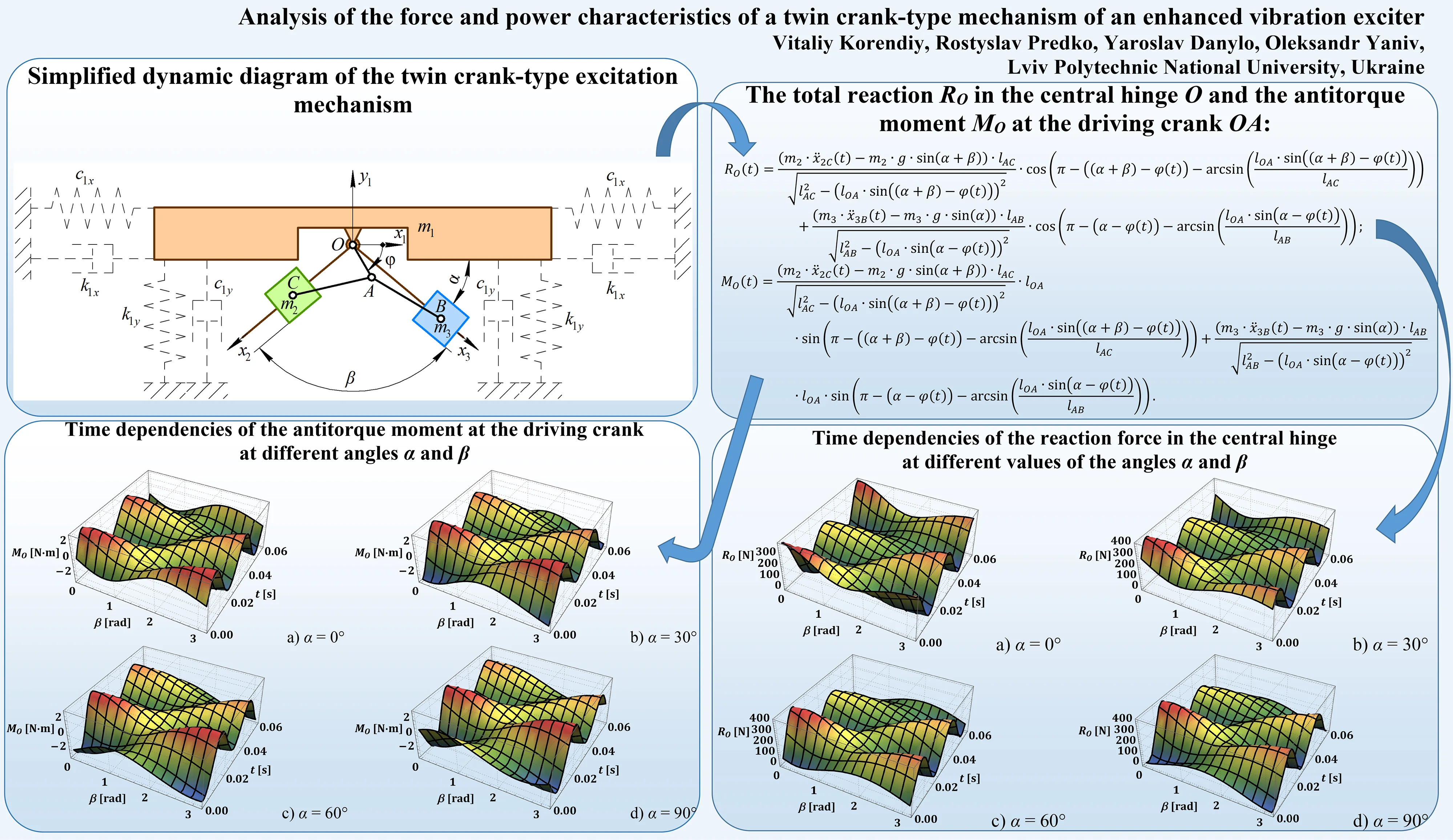
Let’s examine the simplified dynamic diagram of the single-mass oscillatory system presented in Fig. 1. The system comprises a working member (mass ) suspended from a stationary base by spring-damper elements. The latter are characterized by the corresponding vertical and horizontal damping and stiffness coefficients denoted as , , , and , respectively.
Fig. 1Simplified dynamic diagram of the twin crank-type excitation mechanism
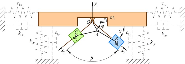
The angular position of the actuating crank OA with respect to the horizontal axis is described by the angle , which varies over time (Fig. 1). The directions of motion of the sliders B and C, which represent the disturbing bodies of the masses and , respectively, are determined by controllable angles and . The sliders are actuated by the connecting rods (AB, AC) attached to the crank OA at the hinge A and connected to the sliders via the hinges B and C, respectively. In order to uniquely describe the motion of the twin crank-type excitation mechanism, the following generalized coordinate is employed: angular position of the actuating crank relative to the rightward-directed horizontal axis Under the steady-state operational conditions, when the angular speed of the crank OA is almost constant , the angle can be described as follows: . In such a case, the inertial and gravity forces acting upon the disturbing bodies (sliders) B and C define the excitation forces of the oscillatory system and the antitorque moment of the crank, which are to be considered while performing further investigations.
2.2. Kinematic and dynamic characteristics of the excitation mechanism
According to the studied dynamic diagram of the twin crank-type excitation mechanism, the analytical expressions describing the positions (coordinates) of the disturbing bodies (sliders B and C) at the corresponding inertial reference systems and can be derived as follows:
where , , are the lengths of the corresponding rods OA, AB, and AC.
All the other kinematic characteristics of the disturbing bodies (sliders B and C), i.e., velocities , and accelerations , , can be calculated by differentiating corresponding Eqs. (1) and (2) with respect to time. The total reaction in the central hinge O and the antitorque moment at the driving crank OA, which are generated due to the action of the gravitational and inertial forces upon the disturbing bodies (sliders B and C), can be determined as follows:
While performing further numerical modeling in the Mathematica software, the influence of different inertial, geometrical, and excitation parameters on the force and power characteristics of the twin crank-type excitation mechanism is to be investigated.
3. Results and discussion
3.1. Analyzing the reaction force in the central hinge of the crank-type mechanism
Let us consider the following inertial, geometrical, and excitation parameters of the twin crank-type excitation mechanism [16, 17]: 1 kg, 0.015 m, 0.08 m, 104.7 rad/s (i.e., the crank rotates at the constant frequency of 1000 rpm). The angles and defining the angular positions of the disturbing bodies guidelines are the controllable parameters influencing the kinematic, dynamic, force, and power characteristics to be studied.
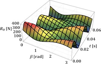
The numerical modeling of the reaction force according to Eq. (3) is performed in the Wolfram Mathematica software at different values of the angles and : 0°, 30°, 60°, 90°, 0…180°. The corresponding results are presented in Fig. 2(a)-(d). In all cases, the peak values of the reaction force are in the range of 390…410 N and are reached at the angles 0° and 180°, i.e., when the sliders move at the same or opposite phases. The smallest peak values, which do not exceed 200 N, are observed at 90°, i.e., when the guides of the sliders are perpendicular. The minimal values of the reaction forces are reached at the angles 0° and 180° and do not exceed –5 N. This means that almost the whole operation time of the mechanism is accompanied by the tension and bending of the driving crank, while compression is very rare.
Fig. 2Time dependencies of the reaction force in the central hinge at different values of the angles α and β
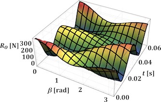
a) 0°
b) 30°
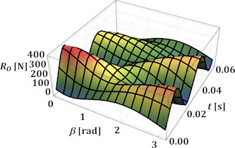
c) 60°
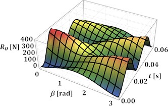
d) 90°
3.2. Investigating the antitorque moment and power at the driving crank
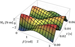
The next stage of this research is dedicated to studying the influence of the angles and on the antitorque moment of all inertial and gravitational forces acting upon the driving crank at the above-mentioned geometrical and operational parameters of the excitation mechanism. The corresponding results showing the time dependencies of the antitorque moment at 0…180° and 0°, 30°, 60°, 90° are presented in Fig. 3(a)-(d), respectively. The considered antitorque moment varies from –3.1 N·m to 3.1 N·m at the angles 0° and 180°, and from –0.7 N·m to 0.7 N·m at 90°. This means that the antitorque moment can be directed either in the opposite direction or in the same direction as the driving motor torque. In such a case, it is necessary to consider the possibilities of implementing additional devices for stabilizing the rotational frequency of the driving motor shaft. Similar investigations on the influence of the antitorque moment fluctuations on the vibratory equipment operation are performed in [4, 7, 10].
Fig. 3Time dependencies of the antitorque moment at the driving crank at different angles α and β
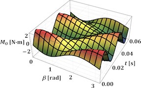
a) 0°
b) 30°
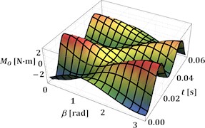
c) 60°
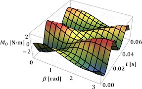
d) 90°
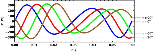
Closing the present research, let us analyze the changes of the antitorque power at the hardest operational conditions when disturbing bodies move synchronously in the same direction ( 0°). In this case, the power varies from approximately –310 W to 310 W regardless of the angle 0°, 30°, 60°, 90°. The obtained results allow for choosing the appropriate driving motor and defining the input parameters for developing the frequency stabilization mechanisms or systems.
Fig. 4Time dependencies of the antitorque power at different angles α and β= 0°
4. Discussion
The optimal configuration of the excitation mechanism depends on the technological operation to be performed by the vibratory machine: conveying, compacting, screening, or sieving. Each operation requires the specific trajectory and other kinematic characteristics (velocities, accelerations) of the working member to be provided for different materials being processed. The maximal and minimal lengths of the links of the excitation mechanism depend on the overall sizes of the technological equipment, in which it is used. Comprehensive research on the influence of the geometrical parameters of the twin crank-slider excitation mechanism on its dynamic behavior is performed in [16] and [17]. In particular, these papers thoroughly consider the possibilities of generating rectilinear, elliptical, and circular oscillations of the working member in order to perform compacting, conveying, and sieving operations. The present paper is focused on the analysis of inertial and gravitational forces acting upon the elements of the excitation mechanism, as well as determining the influence of its specific geometrical parameters (inclination angles of the guides) on the antitorque moment applied to the driving crank. Due to the limited paper length, the effect of other geometrical parameters defining the motion trajectory of the working member on the force characteristics of the mechanism is not analyzed. Further research may be dedicated to these problems. The designers of various vibratory equipment (conveyors, feeders, hoppers, screens, sieves, compacting machines, polishing machines, and other technological equipment) may use the results of the present investigations for approximate determination of the required force, power, and strength characteristics of the specific elements of the machines’ drives, particularly, electric motors, clutches, bearings, couplings, joints, shafts, guides, etc.
5. Conclusions
The paper is focused on determining the force and power characteristics of the twin-crank-type mechanism of an enhanced vibration exciter. The corresponding simplified dynamic diagram is developed, and the equations describing its basic kinematic and dynamic parameters are deduced. The mathematical modeling is performed at the prescribed inertial, geometrical, and excitation parameters of the twin crank-type excitation mechanism taking into account the possibilities of changing the angles and defining the angular positions of the disturbing bodies guidelines. The peak values of the reaction forces of about 410 N and antitorque moments of approximately 3.1 N·m are reached at the angles 0° and 180° regardless of the angle . The maximal antitorque power is 310 W, which allows for choosing the appropriate driving motor. The research findings are valuable for the improvement of the crank-type vibration exciters.
References
-
S. Ogonowski and P. Krauze, “Trajectory control for vibrating screen with magnetorheological dampers,” Sensors, Vol. 22, No. 11, p. 4225, Jun. 2022, https://doi.org/10.3390/s22114225
-
S. Kilikevičius, K. Liutkauskienė, E. Uldinskas, R. El Banna, and A. Fedaravičius, “Omnidirectional manipulation of microparticles on a platform subjected to circular motion applying dynamic dry friction control,” Micromachines, Vol. 13, No. 5, p. 711, Apr. 2022, https://doi.org/10.3390/mi13050711
-
J. Wodecki, P. Krot, A. Wróblewski, K. Chudy, and R. Zimroz, “Condition monitoring of horizontal sieving screens-a case study of inertial vibrator bearing failure in calcium carbonate production plant,” Materials, Vol. 16, No. 4, p. 1533, Feb. 2023, https://doi.org/10.3390/ma16041533
-
V. Gurskyi, V. Korendiy, P. Krot, R. Zimroz, O. Kachur, and N. Maherus, “On the dynamics of an enhanced coaxial inertial exciter for vibratory machines,” Machines, Vol. 11, No. 1, p. 97, Jan. 2023, https://doi.org/10.3390/machines11010097
-
V. Korendiy and O. Kachur, “Locomotion characteristics of a wheeled vibration-driven robot with an enhanced pantograph-type suspension,” Frontiers in Robotics and AI, Vol. 10, p. 1239137, Aug. 2023, https://doi.org/10.3389/frobt.2023.1239137
-
D. Lin et al., “A rigid-flexible coupled dynamic model of a flip-flow vibrating screen considering the effects of processed materials,” Powder Technology, Vol. 427, p. 118753, Sep. 2023, https://doi.org/10.1016/j.powtec.2023.118753
-
J. Feliks, P. Tomach, D. Foszcz, T. Gawenda, and T. Olejnik, “Research on the new drive of a laboratory screen with rectilinear vibrations in transient states,” Energies, Vol. 14, No. 24, p. 8444, Dec. 2021, https://doi.org/10.3390/en14248444
-
V. Korendiy, V. Gursky, O. Kachur, P. Dmyterko, O. Kotsiumbas, and O. Havrylchenko, “Mathematical model and motion analysis of a wheeled vibro-impact locomotion system,” Vibroengineering Procedia, Vol. 41, pp. 77–83, Apr. 2022, https://doi.org/10.21595/vp.2022.22422
-
O. Kachur and V. Korendiy, “Dynamic behavior of vibratory screening conveyor equipped with crank-type exciter,” in Lecture Notes in Mechanical Engineering, pp. 44–53, May 2023, https://doi.org/10.1007/978-3-031-32774-2_5
-
A. Sinha, S. K. Bharti, A. K. Samantaray, G. Chakraborty, and R. Bhattacharyya, “Sommerfeld effect in an oscillator with a reciprocating mass,” Nonlinear Dynamics, Vol. 93, No. 3, pp. 1719–1739, Apr. 2018, https://doi.org/10.1007/s11071-018-4287-x
-
M. Buzzoni, M. Battarra, E. Mucchi, and G. Dalpiaz, “Motion analysis of a linear vibratory feeder: Dynamic modeling and experimental verification,” Mechanism and Machine Theory, Vol. 114, pp. 98–110, Aug. 2017, https://doi.org/10.1016/j.mechmachtheory.2017.04.006
-
V. V. Mikheyev, “New type of vibration generator with vibratory force oriented in preferred direction,” Journal of Vibration Engineering and Technologies, Vol. 6, No. 2, pp. 149–154, Jun. 2018, https://doi.org/10.1007/s42417-018-0025-4
-
G. F. Alışverişçi, “The nonlinear behavior of vibrational conveyers with single-mass crank-and-rod exciters,” Mathematical Problems in Engineering, Vol. 2012, pp. 1–17, Jan. 2012, https://doi.org/10.1155/2012/534189
-
H. Li, C. Liu, L. Shen, and L. Zhao, “Vibration characteristics of an industrial-scale flip-flow screen with crank-link structure and parameters optimization,” Shock and Vibration, Vol. 2021, pp. 1–16, Sep. 2021, https://doi.org/10.1155/2021/2612634
-
V. Korendiy, O. Lanets, O. Kachur, P. Dmyterko, and R. Kachmar, “Determination of inertia-stiffness parameters and motion modelling of three-mass vibratory system with crank excitation mechanism,” Vibroengineering Procedia, Vol. 36, pp. 7–12, Mar. 2021, https://doi.org/10.21595/vp.2021.21924
-
V. Korendiy, V. Gursky, P. Krot, and O. Kachur, “Dynamic analysis of three-mass vibratory system with twin crank-slider excitation mechanism,” Vibrations in Physical Systems, Vol. 34, No. 2, pp. 2023226-1–2023226-9, Jan. 2023, https://doi.org/10.21008/j.0860-6897.2023.2.26
-
V. Korendiy, O. Kachur, R. Predko, O. Kotsiumbas, R. Stotsko, and M. Ostashuk, “Generating rectilinear, elliptical, and circular oscillations of a single-mass vibratory system equipped with an enhanced twin crank-type exciter,” Vibroengineering Procedia, Vol. 51, pp. 8–14, Oct. 2023, https://doi.org/10.21595/vp.2023.23657
About this article

The authors have not disclosed any funding.
The datasets generated during and/or analyzed during the current study are available from the corresponding author on reasonable request.
The authors declare that they have no conflict of interest.
