Abstract
This paper addresses the demand for high-precision micro-gravity simulation experiments on large spacecraft and presents the design of a single-axis aerostatic rotary table with a high load capacity and low disturbance torque. Firstly, the structure of the aerostatic rotary table is analyzed, and the physical and mathematical models of the aerostatic pressure thrust bearing are established. Computational fluid dynamics methods are then employed to investigate the impact of three different aperture throttle orifices on the bearing performance. Through extensive research on the flow field of the bearing air film, it is discovered that changes in the aperture of the throttle orifices directly influence the pressure distribution, turbulence intensity, and gas vortex generation, thereby affecting the performance and stability of the bearing. Based on the calculation results, a single-axis aerostatic rotary table with a throttle orifice diameter of 0.1 mm is manufactured, and tests are conducted to measure its disturbance torque and load capacity. The test results demonstrate that the disturbance torque of the aerostatic rotary table is less than 9.2×10⁻⁵ N·m, and the rated load capacity exceeds 1000 kg. Finally, the research findings offer a theoretical foundation and data support for the design and development of aerostatic rotary table with high load capacity and low disturbance torque. This advancement paves the way for a superior solution in conducting precise micro-gravity simulation tests on large spacecraft.
Highlights
- A new type of high-load-capacity, low-disturbance-torque single-axis aerostatic rotary table was designed.
- A single-axis aerostatic rotary table with a throttle orifice diameter of 0.1 mm has been manufactured and subjected to a series of tests to measure its disturbance torque and load capacity.
- A comprehensive investigation into the flow dynamics of the bearing air film has revealed that alterations in the aperture of the throttle orifices exert a direct impact on the pressure distribution, turbulence intensity, and gas vortex generation.
1. Introduction
The frequency of human space exploration activities has increased with the advancement of space technology, resulting in more complex and precise requirements for spacecraft tasks. This has created an urgent need for high-precision micro-gravity simulation technology [1]-[3]. The aerostatic rotary table system offers an ideal solution for achieving precise spacecraft ground simulation to address this demand [4]-[6].
The aerostatic rotary table system utilizes the air float bearing as its core component and employs high-pressure gas to create a thin gas film between the spacecraft and the bearing base, effectively simulating a micro-gravity environment [7]-[8]. This allows for precise attitude and motion simulation. In the field of air float system design, development, and utilization, numerous explorations have been conducted by esteemed researchers in the United States, Russia and China. As early as 1959, the United States Army Ballistic Missile Agency developed the first aerostatic rotary table, a remarkable achievement in its time. This aerostatic rotary table was primarily utilized for satellite attitude simulation, with a maximum load capacity of 400 kg, demonstrating its remarkable precision and stability [9]. Subsequently, in 1967, the China Academy of Space Technology developed a three-axis aerostatic rotary table for attitude control simulation of recoverable Earth orientation observation satellites. In collaboration with Russian design units at the beginning of this century, they produced a large, high-precision three-axis aerostatic rotary table with a maximum load capacity of 1000 kg and a vertical axis disturbance torque less than 2.3×10⁻³ N·m. It is used to eliminate initial offset simulation of spacecraft [10]. In 2003, Honeywell Space Laboratory in the United States designed a connected structure aerostatic rotary table for satellite dynamic control test. This aerostatic rotary table has a maximum load capacity of 1360 kg and can reduce system disturbance torque to 1.33×10⁻³ N·m [11]. Additionally, the European Space Agency, Germany, and Japan have also developed various forms of aerostatic rotary table to meet the specific needs of their space missions [12]-[14]. In recent years, with the diversification of space missions, Liu et al. designed a single-axis aerostatic rotary table with active compensation based on small orifice throttling to meet the needs of ground test verification of the attitude control system of micro/nano satellites. The disturbance torque of the aerostatic rotary table is less than 2×10⁻⁵ N·m, but the rated carrying load capacity is only 50 kg [15]. Du et al. made a theoretical analysis of the 5000 kg triaxial aerostatic rotary table of Shanghai Academy of Spaceflight Technology, proposed a new method for judging the disturbance torque of large axial aerostatic rotary table, and concluded that the maximum disturbance torque of the aerostatic rotary table could be controlled within 9.48×10⁻³ N·m [16]. Hernandez-Herrera et al. developed a three-axis aerostatic rotary table suitable for the verification of attitude control systems of micro-satellites in a vacuum environment and successfully tested the aerostatic rotary table weighing 4.385 kg [17]. Zhang et al. designed an aerostatic rotary table system based on an all-porous bronze throttle to ensure that the rated load of the aerostatic rotary table is 150 kg and the disturbance torque of the aerostatic rotary table is less than 9×10⁻⁴ N·m [18].
In light of the increasingly stringent requirements for simulation accuracy due to the anticipated improvement in spacecraft quality, the design of aerostatic rotary table must address the challenge of enhancing load capacity while minimizing disturbance torque. Consequently, this paper concentrates on investigating the influence of the bearing orifice on the distribution of the flow field within the air film. Additionally, a single-axis aerostatic rotary table with high-load capacity and low disturbance torque is designed, utilizing micro-orifices throttle. The prototype is subjected to simulation and testing, enabling the provision of a solution for conducting future micro-gravity simulation tests on large spacecraft.
2. Modeling
2.1. Structure and working principle of aerostatic rotary table
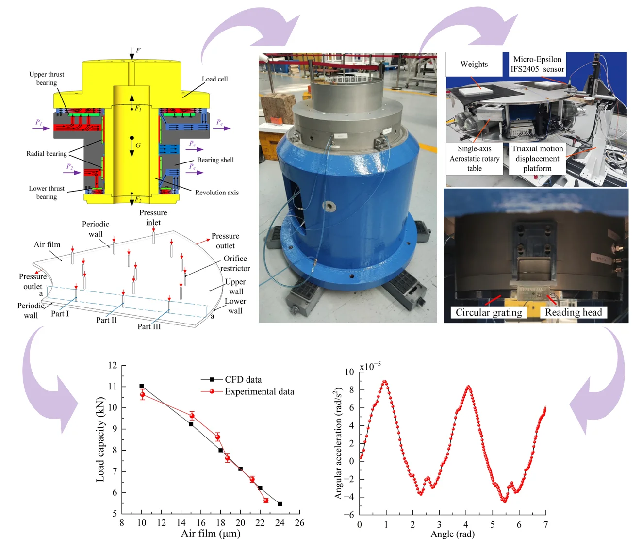
The monobloc aerostatic rotary table utilizes a “T” configuration for its aerostatic rotary table. The thrust bearings consist of upper and lower thrust bearings, as well as radial bearings, which provide axial load capacity to the aerostatic rotary table. During operation, the upper thrust bearing supports the axial load, while the lower thrust bearing restricts the flotation of the aerostatic rotary table and compromises some of its load capacity. On the other hand, the radial bearings offer radial load capacity to the aerostatic rotary table, preventing tilting and reducing frictional losses in the rotor. The structural depiction of the aerostatic rotary table can be observed in Fig. 1.
The aerostatic rotary table, during operation, achieve a state of static equilibrium through the collective influence of their own weight, external loads, as well as the air film forces generated by the upper and lower thrust bearings, they satisfy the following Eq. (1):
where is the load capacity, is gravity, is bearing capacity of upper thrust bearing, bearing capacity of lower thrust bearing.
Therefore, the coupling performance of the upper and lower thrust bearings determines the static and dynamic characteristics of the axial capacity, stiffness, and air consumption of the aerostatic rotary table, the axial capacity of the air floating bearing can be calculated using Eq. (2):
where is the aerostatic rotary table bearing capacity.
Fig. 1Structure diagram of aerostatic rotary table
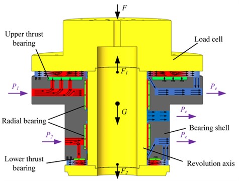
The upper thrust bearing on the aerostatic rotary table has an outer diameter of 440 mm, an inner diameter of 182 mm, and is equipped with three rows of air supply. The lower thrust bearing on the aerostatic rotary table has an outer diameter of 264 mm, an inner diameter of 182 mm, and is equipped with a single row of air supply. Table 1 displays the detailed parameters of the bearings. This study aims to compare and analyze the effects of three different simple straight-orifice throttle orifices (Type A with a diameter of 0.1 mm, Type B with a diameter of 0.08 mm, and Type C with a diameter of 0.06 mm) on the performance of the bearings.
Table 1Dimensions of the aerostatic bearing
Parameters | Unit | Value |
Inner diameters of the upper thrust bearing | mm | 180 |
Out diameters of the upper thrust bearing | mm | 450 |
Distribution circle diameter of upper thrust orifice – I | mm | 232 |
Distribution circle diameter of upper thrust orifice – II | mm | 312 |
Distribution circle diameter of upper thrust orifice – III | mm | 390 |
Number of upper thrust orifice – I | pcs | 24 |
Number of upper thrust orifice – II | pcs | 30 |
Number of upper thrust orifice – III | pcs | 36 |
2.2. Bearing modeling
In the study of aerostatic rotary table conducted in this paper, the high-pressure gas follows the principles of mass conservation, momentum conservation, and energy conservation. The study employs finite element analysis software to address the problem. Given that the high-pressure air passes through the orifice into the bearing film and swiftly disperses into the surrounding environment, the flow can be regarded as isothermal throughout this process.
When high-pressure gas flows through the bearing, it adheres to the mass continuity equation, which is expressed as follows:
where , and , , represent the Cartesian coordinates, is the velocity vector, , , denotes the velocity along the , , directions, is the fluid density, is time.
The equations for conservation of momentum in the , , and directions are expressed as follows:
where is the air pressure in the bearings, is the force on the body, is proportional to the deformation rate of the fluid.
According to the first law of thermodynamics, the expression for the law of conservation of energy is:
where is the temperature, is the fluid heat transfer coefficient, is the specific heat capacity, is the gradient of the temperature, and is the viscous dissipation energy.
2.3. Computational modeling
In previous studies on the grid division of air film in air foil bearings, due to the axial symmetry of the bearings, the bearing model is simplified as a periodic model and structured grid division is used to achieve better computational speed and accuracy [19]-[21]. In this paper, a one-sixth air film of a thrust bearing is taken as the computational domain, and the structured grid division of the bearing air film is performed using Gambit software [22]. To guarantee the accuracy of the calculation, the model is partitioned and the mesh adjacent to the throttle hole is densified. The partitioned grid model is mainly composed of structured grids. By reasonably setting the number of nodes, the grid quality of the model is extremely high, and the grid independence is verified to limit the number of grids within the ideal range while ensuring the computational accuracy. The scale of the grid cells is approximately 1.1 million, with an EquiSize Skew of 0.066. The grid quality meets the computational requirements, and the boundary conditions of the bearing grid are shown in Fig. 2(a), while the bearing grid is shown in Fig. 2(b).
The grid model will be imported into the Computational Fluid Dynamics (CFD) simulation software ANSYS FLUENT 19.2 for calculation after discretization. The flow inside the air film will be simulated using the k-epsilon turbulence model, and the SIMPLE algorithm will be employed for solving. The SIMPLE algorithm is a method used to solve the coupling of velocity and pressure, enforcing mass conservation and obtaining the pressure field through the mutual correction relationship between pressure and velocity. This algorithm has been widely validated by researchers to meet the accuracy requirements [23]. The remaining boundary conditions are as follows:
(1) The absolute ambient pressure is 101325 Pa, and the relative ambient pressure is 0.
(2) The relative inlet pressure at the bearing inlet is 0.5 MPa, and the relative pressure at the bearing outlet is 0.
(3) The high-pressure gas is treated as ideal air with a density of 1.225 kg/m³.
(4) The continuity and velocity convergence residuals are set to 1E-4, indicating the desired level of solution convergence.
Fig. 2Calculation model of thrust bearing
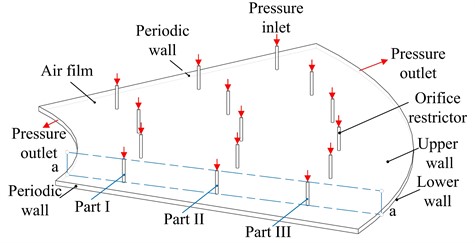
a) Computational domain and boundary conditions
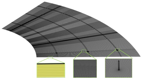
b) Computational meshes
3. Analysis of aerostatic bearing
3.1. Influence of orifice diameters on aerostatic bearing performance
By employing CFD, solutions for three distinct categories of bearings with differing film thicknesses can be computed, Fig. 3 is a concrete calculation. By integrating the pressure acting on the lower surface of the bearing film, the load capacity of the bearing film can be determined as depicted in Eq. (8):
According to the variation of the bearing film load capacity with film thickness, the static stiffness can be obtained using the finite difference method. The solution is given by Eq. (9):
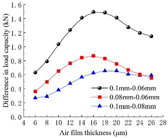
As shown in Fig. 4(a), it is apparent that the diameter of the throttle orifice significantly affects the bearing load capacity. Among the three types of throttle orifices examined in this study, there exists a positive correlation between the diameter of the throttle orifice and the load capacity. Within the range of calculated film thicknesses, the bearing with a throttle orifice diameter of 0.1 mm demonstrates significantly superior load capacity compared to the other two types of bearings. Furthermore, the bearing with a throttle orifice diameter of 0.08 mm exhibits a higher load capacity than the one with a diameter of 0.06 mm. Consequently, under identical film clearance conditions, the bearing load capacity increases as the throttle orifice diameter increases. As the film thickness increases, the load capacity of all three types of bearings displays a decreasing trend. In Fig. 4(b), the disparity in load capacity among the three types of bearings initially increases and subsequently decreases with the increase in film thickness. The most pronounced difference in load capacity between the three types of bearings is observed at a film thickness of approximately 16 μm.
Fig. 3Procedure flow chart
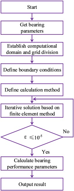
Fig. 4Load capacity of different types of orifices
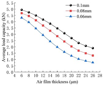
a) Load capacity curves of aerostatic thrust bearing
b) Load capacity difference curves of aerostatic thrust bearing
Fig. 5(a) illustrates the variation trend of bearing stiffness with film thickness for different throttle orifice diameters. The stiffness curves of the three types of bearings with different throttle orifice diameters show an increasing and then decreasing trend with increasing film thickness. However, there are certain differences in the maximum stiffness values and their corresponding film thicknesses among the bearings with different orifice diameters. Comparing the stiffness curves of the three types of bearings, it can be observed that as the throttle orifice diameter decreases, the maximum stiffness value of the bearing shows an increasing trend, and the corresponding film thickness for the maximum stiffness value also decreases accordingly. Furthermore, before reaching the maximum film thickness, bearings with smaller orifice diameters exhibit higher stiffness. However, after reaching the maximum bearing stiffness, bearings with larger throttle orifice diameters show even higher stiffness.
From Fig. 5(b), it can be observed that there is a significant correlation between the size of the throttle orifice diameter and the mass flow rate of the bearing. As the throttle orifice size increases, the gas consumption of the bearing continues to increase. Under conditions of smaller film thicknesses, the differences in gas consumption among the three types of bearings with different orifice diameters are not significant. However, as the film thickness increases and the internal flow resistance decreases, the gas consumption of all three types of bearings increases with increasing film thickness, and the differences in gas consumption among bearings with different orifice diameters become more pronounced, showing clear distinctions. The throttle orifice diameter is an important factor influencing the gas consumption of the bearing, especially at larger film thicknesses, where its impact is more significant.
Fig. 5Stiffness and mass flow rate for various orifice diameter
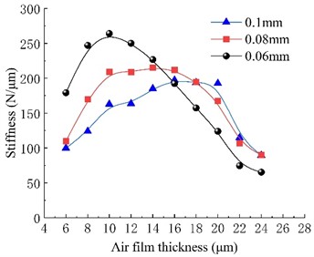
a) Stiffness
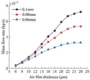
b) Mass flow rate
3.2. Analysis of flow field in gas film of bearings and discussions
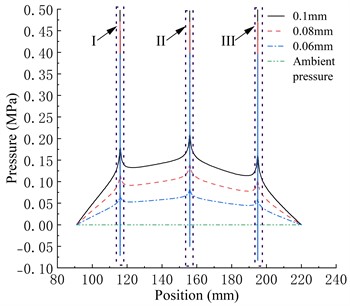
As shown in Fig. 6, the bearing features a three-row intake orifice structure. High-pressure gas enters the air film through the intake orifices, creating localized regions of high pressure around the orifices. This high-pressure gas then diffuses freely in a radial direction towards both ends. Within the air film, high-pressure gas flows into the inner pressure outlet and the outer pressure outlet through the first and third rows of throttle orifices, respectively. As it does so, the gas pressure quickly decreases to the ambient pressure. Simultaneously, a portion of the high-pressure gas flows towards the second row of throttle orifices, forming a central region of high pressure, which serves as the main source of load capacity for the bearing. The gas pressure gradually decreases as it moves from the first row of orifices towards the inner pressure outlet area, and from the third row of orifices towards the outer pressure outlet area. In the regions between the first and second rows of orifices, as well as between the second and third rows of orifices, the gas pressure exhibits a process of initial decrease followed by an increase.
In the comparison of the three types of bearings in the paper, under the same air film thickness, the gas pressure within the Type A bearing in the a-a section is greater than that of the Type B bearing, which is greater than that of the Type C bearing. This is because the gas pressure within the bearing decreases as the diameter of the throttle orifices decreases, resulting in a decrease in the bearing load capacity. With an increase in air film thickness, the overall gas pressure within the bearing decreases. The pressure difference between different throttle orifice bearings at the same position increases, and there is a phenomenon of a rapid decrease followed by a sudden increase in pressure near the throttle orifices. The pressure drop phenomenon near the throttle orifices is an unstable pressure fluctuation, and pressure fluctuations can cause instability in the gas flow velocity within the air film, leading to changes in the bearing load capacity and potential damage. Therefore, it is important to try to avoid or minimize the occurrence of pressure drop phenomena.
When the air film thickness is relatively large, all three types of bearings exhibit pressure drop phenomena, and as the air film thickness continues to increase, negative pressure appears in the pressure drop region. Under the same air film thickness, the peak-to-valley pressure of the Type C bearing is the lowest, and it is the first to exhibit negative pressure at the valley with an increase in air film thickness. The peak-to-valley pressure of the Type A bearing is always higher than the other two types of bearings. The degree of pressure drop at the three rows of throttle orifices in the bearing also varies. The pressure drop peak-to-valley pressure at the second row of throttle orifices is greater than that of the first row and greater than that of the third row. The distribution of the throttle orifices in the bearing is closely related to the degree of pressure drop.
Fig. 6Pressure distribution in different gas film thickness
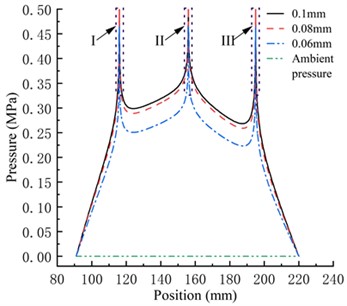
a) 6 μm
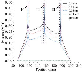
b) 12 μm
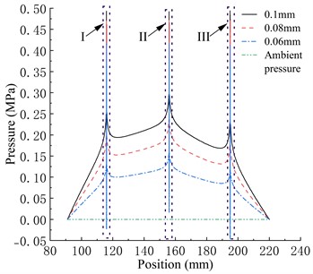
c) 18 μm
d) 24 μm
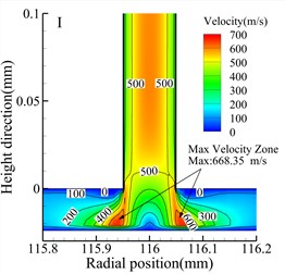
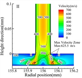
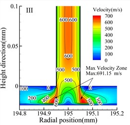
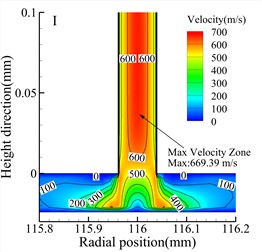
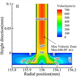
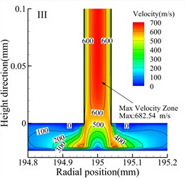
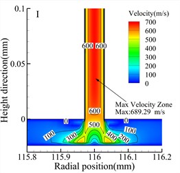
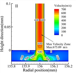
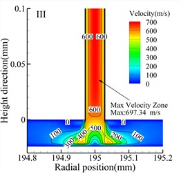
Fig. 7 shows velocity contour maps of the throttle orifices at different positions along the radial section a-a for the three types of bearings. In the Type A bearing, the maximum velocity occurs around the outlet of the three rows of throttle orifices, while in the Type B and Type C bearings, the maximum velocity occurs within the throttle orifices themselves. Comparing the velocity contour maps of the throttle orifices at different positions in the bearings, it is evident that the gas velocity within the throttle orifices at position II is significantly lower than at position I and position III. The maximum gas velocity within the air film also occurs near the throttle orifices at position III, and this is consistent for all three types of bearings. Therefore, it can be concluded that the distribution of the throttle orifices not only affects the pressure distribution within the throttle orifices but also influences the gas velocity within the air film.
Fig. 7Speed cloud diagram of different types (h= 24 μm)
a) Type A bearing position I
b) Type A bearing position II
c) Type A bearing position III
d) Type B bearing position I
e) Type B bearing position II
f) Type B bearing position III
j) Type C bearing position I
h) Type C bearing position II
i) Type C bearing position I
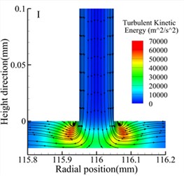
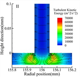
Fig. 8 shows streamline and turbulent kinetic energy contour maps of the throttle orifices at different positions along the radial section a-a for the three types of bearings. Comparing the three types of bearings, it is observed that the maximum turbulent kinetic energy regions occur at the outlet of the throttle orifices for all three types of bearings. Additionally, at the same position, the Type A bearing exhibits higher maximum turbulent kinetic energy compared to the other two types of bearings. However, both the Type A and Type B bearings generate small vortices near the throttle orifices, while the Type C bearing generates larger vortices. There are also noticeable differences in turbulent kinetic energy at different positions within the same type of bearing. For all three types of bearings, the position II exhibits the lowest turbulent kinetic energy, while position III exhibits the highest turbulent kinetic energy.
Fig. 8Streamlines and turbulent kinetic energy contours for various types (h= 24 μm)
a) Type A bearing position I
b) Type A bearing position II
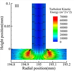
c) Type A bearing position III
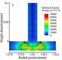
d) Type B bearing position I

e) Type B bearing position II
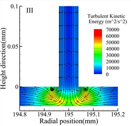
f) Type B bearing position III

j) Type C bearing position I
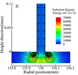
h) Type C bearing position II

i) Type C bearing position I
3.3. Discussion and conclusion
In this paper, the design of the throttling orifices used in the aerostatic rotary table adopts a simple straight orifice structure. This particular design is influenced by both the diameter of the orifice and the thickness of the air film. Furthermore, different orifice diameters also impact the type of throttling that occurs in the bearing. The throttling modes can be categorized into two groups based on the throttling section. The first category is referred to as small orifice throttling and occurs when the air film thickness is small. In this case, the throttling area corresponds to the micro-orifice section. The second category is known as annular throttling and occurs when the air film thickness is large. In this case, the throttling area is the cylindrical surface formed between the periphery of the air supply orifice and the bearing clearance. This is shown in Fig. 9, specifically at the position of annular surface 1.
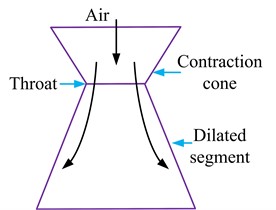
When high-pressure gas flows near the throttling orifice, the gas flow section reaches its minimum at the throttling orifice, and gradually increases as it flows out of the throttling orifice towards the air film. This structure of decreasing and then increasing flow section is similar to the structure of a Laval nozzle, as shown in Fig. 10. A Laval nozzle consists of a convergent section, throat section, and divergent section. When high-pressure gas enters the throat section from the convergent section, the contraction of the throat section accelerates the gas velocity, resulting in a high-speed gas flow that slows down when entering the divergent section. When high-pressure gas proceeds from the convergent section to the throat section, the constriction of the throat section expedites the gas velocity, culminating in the formation of supersonic flow (Mach number > 1). Nevertheless, upon its ingress into the divergent section, the flow velocity decelerates, undergoing a transition from supersonic flow to subsonic flow (Mach number < 1) or transonic flow (Mach number ≈ 1), as shown in Fig. 7.
Fig. 9Schematic diagram of micro-orifices throttle
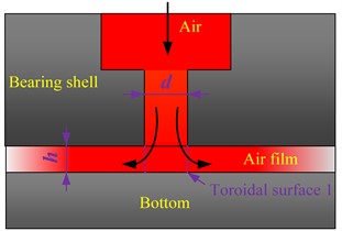
Fig. 10Laval nozzle schematic diagram
In the micro-orifice throttling structure, high-pressure gas enters the bearing's air film via the air cavity above the throttling orifice. The constriction at the micro-orifice section or annular surface 1 generates a high-speed gas flow into the air film. This process can be likened to the Laval effect, induced by the micro-orifice throttle, where the orifice diameter critically influences the static and dynamic properties of the gas bearing. At an air film thickness of 24 μm, Type A bearings exhibit annular throttling at the throttling orifice’s outlet, whereas Types B and C bearings experience small orifice throttling. Throttling effects occur at the narrowest section of the orifice in accordance with the Bernoulli principle, facilitating an energy exchange between the kinetic and potential energy of the high-pressure gas. This exchange results in a velocity increase at the orifice outlet and a subsequent pressure drop, as shown in Fig. 6.
Furthermore, due to the different diameters and positions of the throttling orifices as well as the influence of the Laval effect, Type C bearings exhibit significant velocity changes near the throttling orifice, resulting in more severe pressure drop and the possibility of vortex formation inside the bearing. The generation of vortex flow reduces the stability of the aerostatic rotary table and increases the disturbance torque in the bearing, which should be avoided as much as possible. With the increase in air film thickness, the flow resistance inside the air film decreases, further exacerbating the pressure drop near the throttling orifice and causing instability in the flow field inside the air film, leading to an increase in disturbance torque in the bearing.
Through calculations and analysis of the three types of bearings, the impact of the throttling orifice diameter on the aerostatic rotary table is not only reflected in the bearing's load capacity and stiffness, but also in the pressure, velocity, and flow field inside the bearing air film. When high-pressure gas passes through the throttling orifice and enters the air film, the flow area and flow direction of the gas are changed. High-speed gas flow continuously impacts the bearing wall, leading to flow separation and changes in velocity direction in this region. As a result, complex gas flow phenomena occur in this area, and there are differences in the flow field inside the bearing air film with different orifice sizes and the influence of the Laval effect, as shown in Fig. 8.
Near the throttling orifice, the airflow transitions from orderly laminar flow to turbulent flow, and at this point, the airflow velocity is high and carries a significant amount of kinetic energy. Therefore, the regions with the maximum turbulence in different positions of the three types of bearings are all located at the outlet of the throttling orifice.
4. Experimental research
4.1. Manufacture of aerostatic rotary table
Based on the previous research analysis, the thrust bearing on the aerostatic rotary table studied in this paper uses throttling orifices with a diameter of 0.1 mm. In the manufacturing process, three rows of throttling orifices are used in the thrust bearing of the aerostatic rotary table. To ensure the smoothness of the thrust surface and other requirements, the main body of the bearing, upper and lower thrust plates, and the upper and lower air bearing surfaces where the throttling orifices are located are processed separately. The upper and lower air bearing surfaces and the radial bearing use 5 mm thick tin bronze plates, while the turntable housing, shaft, and load disc are made of 7075 aluminum alloy, with the material parameters as shown in Table 2.
Table 2Material parameters
Material | Elastic modulus (GPa) | Poisson ratio | Density (kg/m3) |
Tin bronze | 110 | 0.35 | 8860 |
7075 aluminum alloy | 70 | 0.3 | 2700 |
The machining of the air bearing surfaces is completed, and subsequently, the thrust plates and bearing body are assembled. Then, laser drilling is used to create the throttling micro-orifices. Fig. 11 illustrates the configuration of the air bearing.
Fig. 11Bearing of aerostatic rotary table
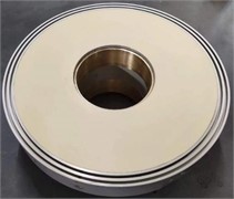
a) Upper thrust bearing
b) Lower thrust bearing
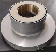
Fig. 12Assembled aerostatic rotary table
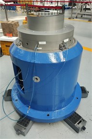
After assembling the air bearing on the rotating shaft, as depicted in Fig. 12, it is necessary to test the thrust plate on the bearing in a ventilated state. This test ensures smooth operation without any sticking, abnormal noise, or vibration. The aerostatic rotary table is designed to have a load capacity of 1000 kg, with a maximum supplied air pressure of 0.5 MPa. To prevent incidents of air film pressure failure that could compromise the precision of the aerostatic rotary table, the supplied air pressure for the upper thrust bearing during testing is set at 0.2 MPa, while the supplied air pressure for the lower thrust and radial bearings is set at 0.4 MPa. By conducting the limit performance test of the air bearing at a lower supplied air pressure, we can gather data to ensure sufficient design margin for the aerostatic rotary table’s usage.
4.2. Disturbance torque experimental research
The disturbance torque measurement device for the aerostatic rotary table is installed at the bottom of the turntable shaft. It consists of a Renishaw RESA30USA300B rotary encoder and a Renishaw RA32BUA300B99V readhead. The pitch of the rotary encoder is 30 μm, and resolution of the readhead is 0.0003″, measurement system accuracy is ±0.95″. The measurement device is shown in Fig. 13. Before the testing process, the bottom of the aerostatic rotary table is leveled using precision shims to ensure that the angle between the turntable and the ground is less than. During the measurement process, a small initial velocity is given to the aerostatic rotary table, and no additional external forces are applied to it afterwards. It can be assumed that the disturbance torque causes the air-bearing shaft to slowly decelerate until it comes to a stop. The dynamic angle of the shaft is recorded by the rotary encoder and readhead, and the angular acceleration of the turntable can be calculated using Eq. (10):
The disturbance torque is obtained by the sum Eq. (11):
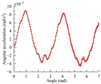
According to the measurements obtained from the 3D modeling software, the moment of inertia of the aerostatic rotary table is 1.029 kg·m2. During the testing process, the maximum angular acceleration recorded was 8.9×10⁻⁵ rad/s2. Therefore, the maximum disturbance torque on the aerostatic rotary table can be calculated as 9.2×10⁻⁵ N·m. The acceleration curve is shown in Fig. 14.
Fig. 13Measurement device of the disturbance torque
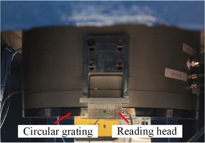
Fig. 14Angular acceleration measurement results
4.3. Load capacity experimental research
The single-axis aerostatic rotary table test system mainly consists of four components: the single-axis aerostatic rotary table system, data measurement and acquisition system, air supply system, and auxiliary fixtures. Fig. 15 and Fig. 16 depict the principle and physical layout of the test equipment. The test platform primarily consists of the air supply system (1), shut-off valve (2), SMC PFM711 flowmeter, resolution is 0.1 L/min (3), SMC gas source processor, resolution 0.05 MPa (4), Data acquisition and processing system (5), Data transmission cable (6), DataPhysics DP240 vibration and noise analyzer (7), Micro-Epsilon IFS2405 confocal displacement sensor, resolution 10 nm (8), weights (9), PCB 356A32 triaxial accelerometer, sensitivity is 100 mv/g (10), single-axis aerostatic rotary table (11), adjustment shims (12), horizontal base (13), air circuit (14) and triaxial motion displacement platform (15).
Fig. 15Test schematic diagram
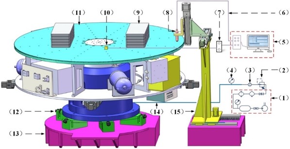
Fig. 16Testing apparatus
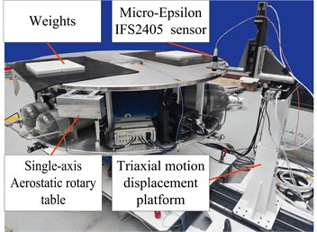
a) Aerostatic rotary table and test instruments
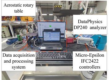
b) Data acquisition and processing equipment
The high-pressure air required for the aerostatic rotary table is provided by the air supply system. The high-pressure air is purified, and the pressure is regulated using a pressure regulator valve. The flow rate is measured using a flowmeter. The high-pressure air is then supplied to the bearing system through micro-orifice throttles, which form a high-pressure air film between the bearing surface and the thrust plate to provide support. During the test, the number of weights is adjusted to change the load on the aerostatic rotary table and thus alter the levitation amount of the aerostatic rotary table. The confocal displacement sensor is mounted on the triaxial motion displacement platform and positioned vertically above the upper thrust surface of the bearing. By recording the displacement changes between the capacitive displacement sensor and the bearing, the variation in the levitation amount of the bearing can be measured.
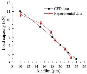
According to Fig. 17, the load capacity of the aerostatic rotary table obtained through experiments and simulations shows good agreement. The numerical simulation results can effectively predict the changes observed in the experimental values, with an error of less than 10 %. During the testing of the aerostatic rotary table, no abnormal phenomena such as self-excited vibration or rotational sticking were observed. The test results also indicate that the thrust bearings using Type A orifices are capable of meeting the design requirement of a 1000 kg load capacity.
Fig. 17Comparison of measured aerostatic rotary table loads and prediction results from CFD
4.4. Performance comparison
As shown in Table 3, the disturbance torque of the aerostatic rotary table designed in this paper is less than 2.3×10⁻³ N·m of the air-bearing table in Reference [10] and 1.33×10⁻³ N·m of the aerostatic rotary table in Reference [11] with the same load capacity. Additionally, it is also better than the 9×10⁻⁴ N·m of the aerostatic rotary table in Reference [18] with a load capacity of 150 kg.
Table 3Performance of different aerostatic rotary table
Aerostatic rotary table | Load capacity (kg) | Disturbance torque (N·m) |
Reference [10] | 1000 | 2.3×10⁻³ |
Reference [11] | 1360 | 1.33×10⁻³ |
Reference [18] | 150 | 9×10⁻⁴ |
Present study | 1000 | 9.2×10⁻⁵ |
5. Conclusions
This study examines the influence of orifice diameters on the flow field and performance of an aerostatic rotary table by investigating bearings with varying orifice sizes. To corroborate the theoretical findings, a single-axis aerostatic rotary table was designed, fabricated, and subjected. The outcomes of both simulation and experimental evaluation yield the subsequent conclusions:
1) The diameter of the orifice markedly influences the performance of bearings. As the diameter of the orifice shrinks, the pressure within the air film diminishes, resulting in a decrease in the load capacity of the aerostatic rotary table. Nonetheless, this decrease in pressure surprisingly enhances the bearing’s stiffness and significantly reduces air consumption.
2) The introduction of high-pressure gas into the air film via the orifice induces the Laval effect. Predesigning the orifice and the air film thickness can prevent the formation of intense eddy currents at the orifice, thus enhancing the stability of the bearings and reducing the disturbing torque.
3) The aerostatic rotary table based on micro-orifice throttling fulfills the design requirements of high load capacity and low disturbance torque. The designed single-axis aerostatic rotary table has a maximum disturbance torque of 9.2×10⁻⁵ N·m and the ultimate load capacity exceeding 1000 kg. This research provides a solution for the precise micro-gravity simulation test of large spacecraft.
4) In this study, the bearing flow field has undergone a simplification, with the primary focus being on the intricate flow field characteristics at the throttle hole of the air float table. It is envisioned that in the subsequent study, a more comprehensive exploration of the overall flow field will be conducted.
References
-
W. Hou et al., “Theoretical and experimental investigations on high-precision micro-low-gravity simulation technology for lunar mobile vehicle,” Sensors, Vol. 23, No. 7, p. 3458, Mar. 2023, https://doi.org/10.3390/s23073458
-
R. Zappulla, J. Virgili-Llop, C. Zagaris, H. Park, and M. Romano, “Dynamic air-bearing hardware-in-the-loop testbed to experimentally evaluate autonomous spacecraft proximity maneuvers,” Journal of Spacecraft and Rockets, Vol. 54, No. 4, pp. 825–839, Jul. 2017, https://doi.org/10.2514/1.a33769
-
H. Yu et al., “Regression model of rotor shape errors based on the ISSA-BP neural network,” Journal of Mechanical Science and Technology, Vol. 38, No. 4, pp. 1925–1938, Feb. 2024, https://doi.org/10.1007/s12206-024-0325-4
-
Y. Wu, C. Li, J. Li, and J. Du, “Lubrication mechanism and characteristics of aerostatic bearing with close-spaced micro holes,” Tribology International, Vol. 192, p. 109278, Apr. 2024, https://doi.org/10.1016/j.triboint.2024.109278
-
J. Li and P. Liu, “Dynamic analysis of 5-DOFs aerostatic spindles considering tilting motion with varying stiffness and damping of thrust bearings,” Journal of Mechanical Science and Technology, Vol. 33, No. 11, pp. 5199–5207, Nov. 2019, https://doi.org/10.1007/s12206-019-1009-3
-
S. Li et al., “Calculation and analysis of equilibrium position of aerostatic bearings based on bivariate interpolation method,” Lubricants, Vol. 12, No. 3, p. 85, Mar. 2024, https://doi.org/10.3390/lubricants12030085
-
B. R. Fernandez, L. Herrera, J. Hudson, and M. Romano, “Development of a tip-tilt air-bearing testbed for physically emulating proximity-flight orbital mechanics,” Advances in Space Research, Vol. 71, No. 10, pp. 4332–4339, May 2023, https://doi.org/10.1016/j.asr.2023.01.005
-
N. Qi, “Micro/low gravity simulation and experiment technology for spacecraft,” (in Chinese), Journal of Astronautics, Vol. 41, No. 6, pp. 770–779, 2020, https://doi.org/10.3873/j.issn.1000-1328.2020.06.014
-
J. L. Schwartz, M. A. Peck, and C. D. Hall, “Historical review of air-bearing spacecraft simulators,” Journal of Guidance, Control, and Dynamics, Vol. 26, No. 4, pp. 513–522, Jul. 2003, https://doi.org/10.2514/2.5085
-
J. Li, X. Mou, W. Sun, T. Yang, and T. Li, “A full physics simulation system for three axis air bearing platform of large satellite,” (in Chinese), Control Engineering, Vol. 3, pp. 22–26, 2001.
-
M. Peck, “An air bearing-based testbed for momentum control systems and spacecraft line of sight,” Advances in the Astronautical Sciences, Vol. 114, pp. 427–446, 2003.
-
F. Wang, X. Cao, Y. Yang, and D. Gao, “Small satellite large angle attitude maneuver hardware-in-the-loop simulation based on three-axis air bearing table,” in AIAA Modeling and Simulation Technologies Conference and Exhibit, Aug. 2006, https://doi.org/10.2514/6.2006-6733
-
T. Shima, M. Saito, K. Fukushima, and K. Yamada, “Automatic balancing for a three-axis spacecraft simulator,” Transactions of The Japan Society for Aeronautical and Space Sciences, Aerospace Technology Japan, Vol. 8, No. 27, pp. 15–22, 2010, https://doi.org/10.2322/tastj.8.pd-15
-
Z. Li and Y. Dong, “Balance of single axis air bearing table based on its swing characteristics,” (in Chinese), Review Science and Technology, Vol. 28, No. 2, pp. 46–49, 2010.
-
Y. Liu, M. Huo, and N. Qi, “Modeling of disturbance torque in an aerostatic bearings-based nano-satellite simulator,” Journal of Systems Engineering and Electronics, Vol. 29, No. 3, p. 618, Jan. 2018, https://doi.org/10.21629/jsee.2018.03.19
-
D. Du, “Research on the optimum parameters and unbanlanced torque based on the offset of mass-center of the air bearing testbed,” (in Chinese), Journal of Mechanical Engineering, Vol. 52, No. 19, p. 102, Jan. 2016, https://doi.org/10.3901/jme.2016.19.102
-
M. Hernandez-Herrera, “Attitude testing platform in a vacuum environment for a lean satellite with an electric thruster,” Journal of Small Satellites, Vol. 8, pp. 849–858, 2019.
-
X. Zhang, Y. Lu, W. Hou, L. Wang, P. Li, and J. Gu, “Development of aerostatic rotary table for micro-gravity test based on porous bronze,” (in Chinese), Journal of Harbin Institute of Technology, Vol. 55, No. 1, pp. 82–88, Jan. 2023, https://doi.org/10.11918/202110064
-
D. Perfetto, C. Pezzella, V. Fierro, N. Rezazadeh, A. Polverino, and G. Lamanna, “FE modelling techniques for the simulation of guided waves in plates with variable thickness,” Procedia Structural Integrity, Vol. 52, pp. 418–423, Jan. 2024, https://doi.org/10.1016/j.prostr.2023.12.042
-
W. Ma, J. Cui, Y. Liu, and J. Tan, “Improving the pneumatic hammer stability of aerostatic thrust bearing with recess using damping orifices,” Tribology International, Vol. 103, pp. 281–288, Nov. 2016, https://doi.org/10.1016/j.triboint.2016.06.009
-
C. Pany, “Panel flutter numerical study of thin isotropic flat plates and curved plates with various edge boundary conditions,” Politeknik Dergisi, Vol. 26, No. 4, pp. 1467–1473, Dec. 2023, https://doi.org/10.2339/politeknik.1139958
-
Sutardi and L. Z. R. Aditya, “Numerical studies of square edge and quadrant edge orifice flow meter performance with different diameter ratios and Reynolds numbers,” in Lecture Notes in Mechanical Engineering, Singapore: Springer Nature Singapore, 2022, pp. 254–264, https://doi.org/10.1007/978-981-19-0867-5_31
-
W. Li, G. Wang, K. Feng, Y. Zhang, and P. Wang, “CFD-based investigation and experimental study on the performances of novel back-flow channel aerostatic bearings,” Tribology International, Vol. 165, p. 107319, Jan. 2022, https://doi.org/10.1016/j.triboint.2021.107319
About this article

This work was supported by the National Natural Science Foundation of China under Grant No. 52305102 and 51875586. China Postdoctoral Science Foundation under Grant No. 2024M752383.
The datasets generated during and/or analyzed during the current study are available from the corresponding author on reasonable request.
Conceptualization, Hechun Yu and Xinjun Kou; methodology, Hechun Yu and Weijie Hou; software, Xinjun Kou and Libin Zang; validation, Guoqing Zhang and Wenbo Wang; formal analysis, Lijia Yan and Yongbo Hao.; investigation, Xinjun Kou and Weijie Hou; data curation, Xinjun Kou and Libin Zang; writing-original draft preparation, Hechun Yu and Xinjun Kou; writing-review and editing, Guoqing Zhang and Wenbo Wang; funding acquisition, Hechun Yu and Yongbo Hao. All authors have read and agreed to the published version of the manuscript.
The authors declare that they have no conflict of interest.
