Abstract
Bearing-rotor system dynamic characteristic is the key influence on high-speed power equipment stability. The experimental investigations focus on the dynamic characteristics of high-speed turbine expansion generator rotor, which was supported by gas aerostatic bearings. Nonlinear dynamic behavior of high-speed turbine expansion generator rotor, including gas film whipping and gas film half-speed whirling, were analyzed in the experiments. Static characteristic tests for effects of bearing supply gas pressure on the bearing axial clearance are carried out to provide the rotor axial position under different bearing supply gas pressure groups, which showed that the bearing thrust performance changed with bearing supply gas pressure. The experimental results of rotor dynamic characteristics under different bearing supply gas pressure groups show that gas film whirling and whipping occurred in the mentioned bearing-rotor system during the speed up process when the axial clearance for two ends were different. The shafting stability under the same axial clearance for two ends is better than the condition under the different bearing axial clearance. The paper gives some measures to improve the high-speed bearing-rotor system stability.
1. Introduction
High-speed turbine expansion generator has the advantages of high speed, compact structure and high power density, which has broad application prospects in the power generation devices of supercritical CO2 power cycle, Organic Rankine Cycle and natural gas pressure energy recovery system, etc. Combined with the characteristics of the above application environment, the aerostatic bearing was one of preferred support styles in high-speed turbine expansion generator. Lubrication medium of aerostatic bearing can take supercritical carbon dioxide, organic working medium and natural gas, which get from operational environment and return to the operational environment. That makes structural design of power cycle system simple and reasonable. From the research technique route of high-speed turbine expansion generator, it was necessary that bearing-rotor dynamic characteristic research were carried out. A large number of scholars take lots of researches on dynamic features of generators and equipments.
Dynamic and static characteristics of hydrostatic and hydrostatic-dynamic hybrid gas lubrication bearing rotor system were studied by experimental and theoretical analysis in Ref. [1-6]. Yang et al. [7] presented a criterion for the stability evaluation of a journal rotor-bearing system. The mechanism of oil whirl and oil whip was illuminated on the basis of a single-disk rotor supported on journal-bearing system test. The practicability of the journal-bearing engineering stability criterion and its methodology was also validated. An existing analytical hydrostatic gas bearing model was extended and modified to guide the bearing design with stiffness anisotropy in Ref. [8]. M. T. Neves [9] studied the influence of the loss coefficient of the throttle on the performance of the gas bearing. The loss factor under supersonic and subsonic velocity was calculated by ANSYS-CFX. The loss factor and the finite element method were used to solve the compressible Reynolds equation. The air film pressure distribution and air consumption were got. Compared with the previous study, the output loss of the throttle is set to constant. The results show that the function chosen by the loss factor has little effect on the bearing capacity of the bearing, but it has a great influence on the bearing air consumption of the bearing. In Ref. [10], The chaotic optimization method, multi-population collaborative strategy and adaptive control parameters are introduced into the genetic algorithms and ant colony optimization algorithm to propose a genetic and ant colony adaptive collaborative optimization algorithm for solving complex optimization problems, in order to overcome the deficiencies of weak local search ability in genetic algorithms and slow global convergence speed in ant colony optimization algorithm in solving complex optimization problems. The Ref. [11] studied the absence of gas stove with a diameter of less than 0.05 mm, used CFD to calculate the loss factor, and solved the pressure distribution of the bearing with a finite difference method. Works of Refs. [11-13] carried out experimental studies on effects of bearing supply gas pressure on bearing rotor system dynamic characteristics. Morosi [14] presented a detailed mathematical model for hybrid lubrication of a compressible fluid-film journal bearing, and built a multi-body dynamics model of a global system comprised of rotor and hybrid journal bearing to study the lateral dynamics of the system by Campbell diagrams and stability maps. They explored the feasibility of applying active lubrication to gas journal bearings by mechatronic system with the pneumatic and dynamic characteristics of a piezoelectric actuated valve system [15].
Based on high-speed turbine expansion generator testing system, experimental investigations are done on effects of the axial clearance on aerostatic bearing rotor dynamic characteristics, which focused on the rotor nonlinear dynamic behavior under different axial clearance. The paper provides technical support for safe operation of aerostatic bearing rotor system and high-speed turbine expansion generator.
2. High-speed double-stage expansion turbine generator testing system
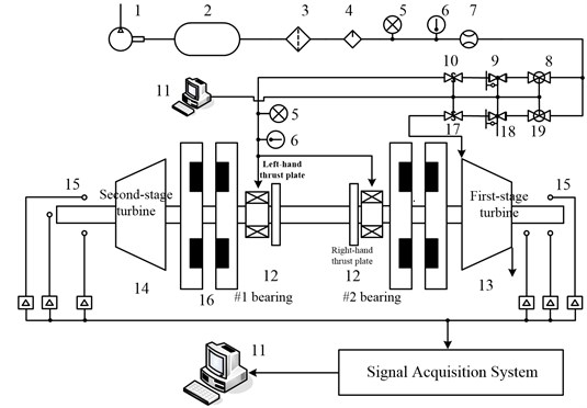
The test rig for a high-speed double-stage expansion turbine generator consists of a vibration signal testing and analysis subsystem, a high-speed double-stage expansion turbine generator test bench body and a bearing supply pressure subsystem, as shown in Fig. 1.
The vibration signal testing and analysis subsystem comprises eddy current displace sensors, accelerometers, and a data-collecting instrument. Three eddy current displacement transducers are placed at the first-stage turbine end for measuring lateral vibration displacement and rotational speed. Two eddy current displacement transducers are placed at the second-stage turbine end for measuring lateral vibration displacement. One eddy current displacement transducer is placed at the second-stage turbine end for measuring axial movement displacement. The measuring range of the sensors is 1 mm. The linearity is 10.4 V/mm, and the range of measuring frequency is from 0 Hz to 10 kHz.
The high-speed double-stage expansion turbine generator test bench body consists of aerostatic bearings, a PM disk type generator and a chassis. The high-speed double-stage expansion turbine generator adopts the PM disk type generator structure, which is composed of a symmetrical PM disk type rotor and a pair of stator windings. The stator winding has four electrode couples. The stator windings were not installed in the test body because the characteristics of the motor were not considered in the paper. Two aerostatic radial-thrust bearings are adopted in the high-speed double-stage expansion turbine generator. The chassis and the stator winding were not shown in Fig. 1. The high-speed double-stage expansion turbine generator has a rated speed of 45000 r/min and a rated power of 10 kW. The cooling system uses air as working fluid. The exterior of the high-speed PM motor is 355 mm long, 200 mm wide, and 230 mm tall.
A centrifugal air compressor, regulating valves, flow sensors, temperature sensors, and pressure sensors make up the bearing supply pressure subsystem. The compressor can provide the maximum pressure of 1.2 MPa and maximum mass flow of 3.90 kg/s. The airflow into the bearings is controlled by regulating valves and by employing an adjustable air pressure regulator connected to the supply air lines. A K-type thermocouple monitors the temperature of the bearing supply gas. A calibrated mass-flow meter measures the mass flow rate into each bearing with an uncertainty of 0.195 kg/s. The regulation valve controls the air pressure in proportion to the rotational speed of the test rotor in the acceleration process. When the commands for changing bearing supply pressures are given, the electro-pneumatic air regulator automatically adjusts the supply pressure, with approximately 0.4 s to 0.5 s time delay.
In Fig. 1, facing the computer, the left-hand bearing is defined as #1 bearing, and the right-hand bearing is defined as #2 bearing. The right-hand turbine is the first-stage turbine, and the left-hand turbine is the second-stage turbine. In the paper, the rotor is driven by high pressure air through the first-stage turbine.
Fig. 1Sketch map of experimental system structure: 1. Air compressor, 2. Gas tank, 3. Filter, 4. Dryer, 5. Pressure gauge, 6. Thermometer, 7. Flow meter, 8. Sub-pipeline pressure stabilizing valve, 9. Sub-pipeline electro-pneumatic air regulator, 10. Sub-pipeline safety shut-off valves, 11. Computer, 12. Radial-thrust gas bearing, 13. First-stage turbine, 14. Second-stage turbine, 15. Eddy current displace sensor, 16. PM discs, 17. Main-pipeline safety shut-off valves, 18. Main-pipeline electro-pneumatic air regulator, 19. Main-pipeline pressure stabilizing valve
2.1. Aerostatic bearings
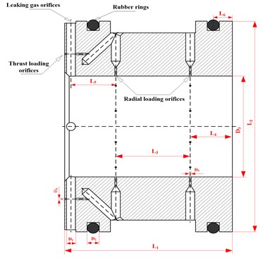
A pair of aerostatic radial-thrust bearings is adopted in the high-speed double-stage expansion turbine generator. A schematic of the aerostatic bearing is shown in Fig. 2. Hydrostatic lubrication is achieved by a double row of orifices along the axis. The number of the radial loading orifices is ten by the single row. The four leaking gas orifices along circumferential the uniform distribution is used to exhaust gas of the thrust bearings. The load-bearing capacity of the thrust bearing is attributed to the sixteen orifices along the circumference. The rubber rings are adopted to improve the performance of the bearings. Table 1 presents the geometric characteristics of the aerostatic bearings.
Table 1Geometric characteristics of the aerostatic bearings
Symbol / Unit | Values | Symbol / Unit | Values |
L1 / mm | 40.00 | D1 / mm | 2.00 |
L2 / mm | 52.00 | D2 / mm | 3.10 |
L3 / mm | 17.00 | D3 / mm | 25.00 |
L4 / mm | 11.50 | D4 / mm | 0.30 |
L5 / mm | 10.50 | D5 / mm | 0.30 |
L6 / mm | 3.65 | – | – |
Fig. 2Schematic of the aerostatic bearings
2.2. The PM disk type generator rotor
The PM disk type generator rotor is the double thrust plate rotor structure of a double-stage radial-turbine coaxial with four PM discs. The double-stage turbines and the four PM discs are installed on the rotor by cylindrical bonds. The nuts are used to fix at the axial direction outside the turbines. The four discs are the same structure size. Eight PM blocks are arranged by N-S electrode alternately along the circumferential direction on every disc. Table 2 presents the geometric characteristics of the PM rotor. The schematic diagram of the rotor for three dimensional structure is shown in Fig. 3.
Table 2Geometric characteristics of the PM rotor
Geometric parameters | Unit | Values |
Bearing span | mm | 112.75 |
Disc mass | kg | 0.31 |
Inside disc span | mm | 169.70 |
Outside disc span | mm | 195.28 |
Rotor mass | kg | 2.49 |
Radial turbine mass | kg | 0.24 |
Rotor axial length | mm | 372.24 |
Impeller span | mm | 286.28 |
Fig. 33D structure schematic diagram of the rotor

3. Static characteristic tests of axial clearance
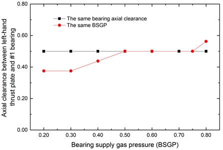
Shutting off the main-pipeline electro-pneumatic air regulator made the rotor stay still. When the axial clearance between the left-hand thrust plate and #1 bearing was zero, it was taken as the axial clearance benchmark null position. When the axial clearance between the right-hand thrust plate and #2 bearing was zero, it was taken as a maximum of the axial clearance. The standardized method was used to quantify the axial clearance based on the maximum of the axial clearance. The maximum of the axial clearance was 1 after treatment. The axial clearance value between the left-hand thrust plate and #1 bearing was measured by an eddy current displacement transducer when the BSGP for #1 bearing and # 2 bearing change from 0.20 MPa to 0.80 MPa. The BSGP value was also made dimensionless based on 1.00 MPa. During the whole course of tests, the BSGP parameters of #1 bearing and #2 bearing increased from 0.20 to 0.80 by 0.05 increments. The figures from 4 to 6 were plotted by BSGP on the vertical axis and axial clearance on the horizontal based on the test data.
The straight line parallel with the vertical axis represented that the axial clearance value between left-hand thrust plate and #1 bearing was equal to that between right-hand thrust plate and #2 bearing in Fig. 4. This straight line was not obtained by the experiment. It’s only as a reference curve. The points of the other broken line represented the #1 bearing axial clearance values when both #1 and #2 BSGP is the same. In theory, the bearing axial clearance is the same on both sides under the same BSGP if #1 and #2 bearing have the same thrust performance. The experimental results in Fig.4 showed that the thrust performances for #1 and #2 bearing existed differences. The bearing axial clearance is different when the BSGP is the same both #1 and #2 bearing.
As shown in Fig. 4, when the #1 and #2 BSGP with the same value was less than 0.60, the axial clearance for #1 bearing end was less than that for #2 bearing end. When the #1 and #2 BSGP with the same value was more than 0.80, the axial clearance for #2 bearing end was less than that for #1 bearing end. The thrust performance of #1 bearing changed obviously with BSGP. When BSGP for #1 and #2 bearing were both 0.50, or 0.60, or 0.70, or 0.80, the axial clearances for two ends were the same.
Fig. 4Axial clearance changing with BSGP
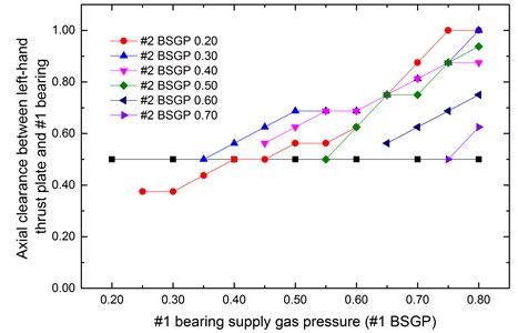
The Fig. 5 was plotted by #2 BSGP on the vertical axis and axial clearance on the horizontal based on the test data. The six broken lines in Fig. 5 represented that the axial clearance for #1 bearing end changed with #2 BSGP when #1 BSGP remained unchanged.
The six broken lines were all under the straight line parallel with the vertical axis, which indicated that the axial clearances for #1 bearing end were less than that for #2 bearing when #2 BSGP was greater than #1 bearing. The axial clearances for #1 bearing end turned smaller and smaller with the increase of #2 BSGP when #1 BSGP remained unchanged. The axial clearances for two ends were the same, when BSGP for #1 and #2 bearing were respectively (0.50, 0.55) or (0.70, 0.75).
The Fig. 6 was plotted by #1 BSGP on the vertical axis and axial clearance on the horizontal based on the test data. The six broken lines in Fig. 6 represented that the axial clearance for #1 bearing end changed with #1 BSGP when #2 BSGP remained unchanged. The most points of lines were up the straight line with the same bearing axial clearance except the BSGP for #1 and #2 bearing at (0.25, 0.20), (0.30, 0.20) and (0.35, 0.20). The axial clearances for two ends were the same, when BSGP for #1 and #2 bearing were respectively (0.40, 0.20) or (0.45, 0.20) or (0.75, 0.70).
Fig. 5Axial clearance changing with #2 BSGP
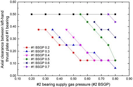
Fig. 6Axial clearance changing with #1 BSGP
The static characteristic results showed that the bearing thrust performance for #1 and #2 bearings changed with bearing supply gas pressure, and the bearing thrust performance for #1 bearing changed obviously. Combined with the static characteristic results, the axial position of the rotor can be confirmed according to the bearing axial clearance value under different bearing supply gas pressure groups. The bearing supply gas pressure groups were obtained as shown in Table 3 when the axial clearances for two ends were the same.
Table 3BSGP groups under the same axial clearance
BSGP groups | |||||||||||
#1 bearing | 0.50 | 0.60 | 0.70 | 0.75 | 0.50 | 0.70 | 0.35 | 0.55 | 0.40 | 0.45 | 0.75 |
#2 bearing | 0.50 | 0.60 | 0.70 | 0.75 | 0.55 | 0.75 | 0.30 | 0.50 | 0.20 | 0.20 | 0.70 |
4. Rotordynamic experiments of high-speed turbine generator under different axial clearances
During the rotordynamic characteristic results of high-speed turbine generator, the first-stage turbine was used to drive the coaxial rotor by high pressure air. Based on the static characteristic results, rotordynamic experiments were carried out in four different cases in Table 4. In order to the accuracy and repeatability of the test results, bearing supply gas pressure groups of the same axial clearance were selected, as shown in Table 2 E3 and E4. In order to rule out the influence of bearing supply gas pressure, BSGP value of #2 bearing in E3 was between the value in E1 and in E2. Vibration data for #2 bearing end were adopted to contrastively analyze the rotordynamic characteristics.
Table 4BSGP groups
Experiment number | #1 bearing axial clearance | #2 bearing axial clearance | #1 BSGP | #2 BSGP |
E1 | 0.3125 | 0.6875 | 0.60 | 0.80 |
E2 | 0.75 | 0.25 | 0.65 | 0.50 |
E3 | 0.50 | 0.50 | 0.75 | 0.70 |
E4 | 0.50 | 0.50 | 0.75 | 0.75 |
4.1. Characteristic analysis for E1 and E2
The Fig. 7 is a 3D spectrum for local amplification of low frequency area. Low frequency vibration M with 51 Hz frequency and 25 μm amplitude appeared at 10898 r/min. Frequency value of the low frequency M didn’t change with power frequency increase, which presented feature of gas film whipping.
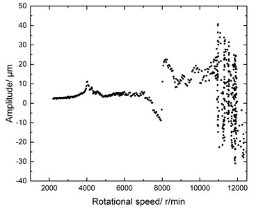
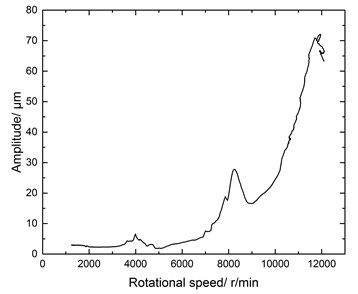
As shown in Fig. 8, when gas whip occurred, rotational speed increased from 10898 r/min to 11917 r/min, and the power frequency vibration amplitude increased from 30 μm to 70 μm accordingly. The rotor didn’t pass the critical speed area at 19717 r/min. In the bifurcation diagram shown in Fig. 9, the chaos characteristics were presented after gas film whipping. The boundary of chaos presented expanding tendency. Axes track and spectrum characteristic in the chaotic region were shown in Fig. 10.
Fig. 73D spectrum for local amplification of low frequency area for E1
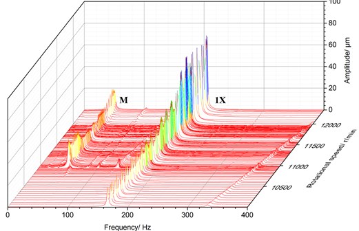
Fig. 8Frequency response curve for E1
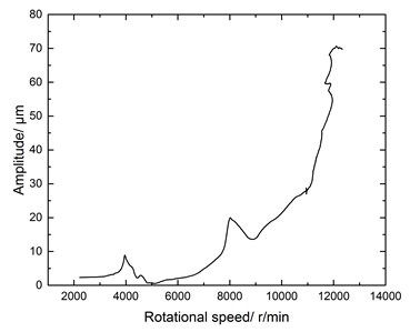
Fig. 9Bifurcation diagram of CF area for low frequency area of E1
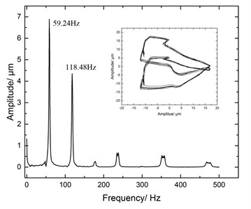
The rotor dynamic response for E2 was different of the E1. There were three low frequencies, N, Q and P shown in Fig. 11. It for N was a half-speed whirling at the speed of 7109 r/min. The whirl frequency was 59.24Hz, and the whirl amplitude was 6.00 μm. The whirl ratio was 0.50. The period 2 bifurcation feature was presented in Fig. 12 when half-speed whirling appeared. The Fig. 13 showed the axes track and spectrum characteristic of half-speed whirling.
Gas film whipping occurred at 10488 r/min, and the corresponding frequency and amplitude respectively were 50 Hz, and 25 μm, as shown in Q area of Fig. 11. The gas film whipping disappeared from 10782 r/min to 11502 r/min and reappeared at 11502 r/min in P area of Fig. 11. The chaos feature developed along with the appearing of gas film whipping on the bifurcation diagram, just as gas film whipping of Q and P area.
Fig. 10Axes track and spectrum analysis at 11289 r/min
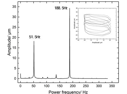
Fig. 113D spectrum for local amplification of low frequency area for E2
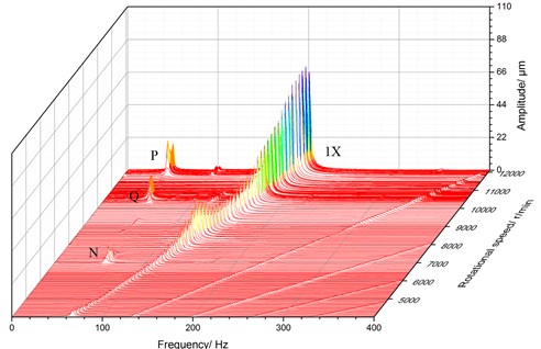
Fig. 12Bifurcation diagram for E2
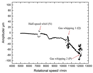
Fig. 13Axes track and spectrum analysis at 7109 r/min
The frequency response curve was similar to the E1 in Fig. 14.
Fig. 14Frequency response curve for E2
4.2. Characteristic analysis for E3 and E4
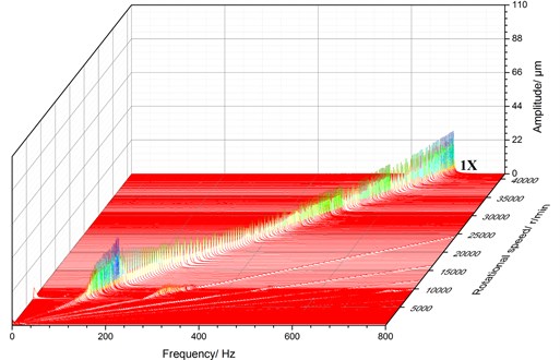
In the experiment E3, gas film whipping and gas film whirling didn’t appear during the speed up process, and the highest speed in the E3 was at 41000 r/min, as shown in Fig. 15.
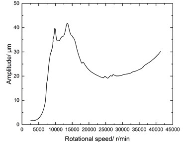
The region of critical speed appeared ahead of time relative to E1 and E2. The peak in the region of critical speed was at 9850 r/min, and the corresponding maximal amplitude was 35 μm in Fig. 16, which was half of E1 and E2. Bearing supply gas pressure value of #2 bearing in E3 was selected between E1 and E2. Effects of bearing supply gas pressure on the lateral vibration were excluded.
Based on above comparative analysis from E1 to E3, rotordynamic characteristics were better when the axial clearances for two ends were the same.
Fig. 153D spectrum for E3
In order to the accuracy and repeatability of the test results, the other bearing supply gas pressure groups of the same axial clearance were selected, as in E4 of Table 2. As shown in Fig. 17, gas film whipping and gas film whirling didn’t appear during the speed up process, and the highest speed in the E4 was at 41000 r/min. There were two peak values at 9775 r/min and 13510 r/min in the region of the critical speed. The other features in E3 are similar to E4.
According to the comparison and analysis, gas film whirling and whipping occurred in the mentioned bearing-rotor system during the speed up process when the axial clearance for two ends were different, which reduce the bearing-rotor system stability. When the axial clearance for two ends were the same, gas film whirling and whipping disappeared under the same condition, and the bearing-rotor system in the paper had better stability.
Fig. 16Frequency response curve for E3
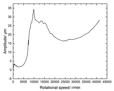
Fig. 173D spectrum for E4
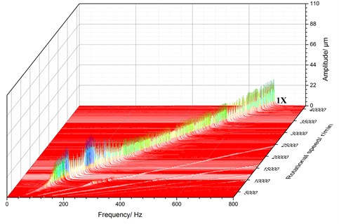
Fig. 18Frequency response curve for E4
5. Conclusions
Dynamic response characteristics of high-speed turbine expansion generator rotors are discussed in the paper by the experimental methods.
Effects of BSGP on the axial clearance characteristics are given by static characteristic tests. The static characteristic results provide support for confirming BSGP groups of speed up experiment. Meanwhile the rotor axial position under different BSGP groups can be got to provide basic data of rotor dynamic analysis.
Rotor dynamic characteristic experimental results show that shafting stability under the same axial clearance for two ends is better than the condition under the different axial clearance. The paper gives one measure for improving bearing-rotor system stability, which is also good to enhance operational stability of high-speed turbine expansion generator rotor.
References
-
Andrés L. S., Ryu K. Hybrid gas bearings with controlled supply pressure to eliminate rotor vibrations while crossing system critical speeds. Journal of Engineering for Gas Turbines and Power, Vol. 130, 2008, https://doi.org/10.1115/1.2966391.
-
Andrés L. S., et al. On the predicted performance of oil lubricated thrust collars in integrally geared compressors. Journal of Engineering for Gas Turbines and Power, Vol. 137, Issue 5, 2014, p. 52502-2.
-
Cable T. A., Andrés L. S., Wygant K. On the predicted effect of angular misalignment on the performance of oil lubricated thrust collars in integrally geared compressors. Journal of Engineering for Gas Turbines and Power, Vol. 139, Issue 4, 2017, https://doi.org/10.1115/1.4034722.
-
Andres L. S. Hybrid flexure pivot-tilting pad gas bearing: analysis and experimental validation. Journal of Tribology, Vol. 128, Issue 7, 2006, p. 551-558.
-
Qin Z. Y., Yan S. Z., Chu F. L. Dynamic characteristics of launch vehicle and spacecraft connected by clamp band. Journal of Sound and Vibration, Vol. 330, Issue 10, 2011, p. 2161-2173.
-
Qin Z. Y., Yan S. Z., Chu F. L. Dynamic analysis of clamp band joint system subjected to axial vibration. Journal of Sound and Vibration, Vol. 329, Issue 21, 2010, p. 4486-4500.
-
Yang J., Yang K., Chen C., et al. A criterion for evaluation stability of journal bearings-rotor system. Proceedings of GT2008, ASME Turbo Expo: Power for Land, Sea and Air, 2008.
-
Liu L. X., Spakovszky Z. S. Effects of bearing stiffness anisotropy on hydrostatic micro gas journal bearing dynamic behavior. Journal of Engineering for Gas Turbines and Power, Vol. 129, Issue 1, 2007, p. 177-184.
-
Neves M. T., Schwarz V. A., Menon G. J. Discharge coefficient influence on the performance of aerostatic journal bearings. Tribology International, Vol. 43, Issue 4, 2010, p. 746-751.
-
Deng W., Zhao H., Zou L., et al. A novel collaborative optimization algorithm in solving complex optimization problems. Soft Computing, Vol. 21, Issue 15, 2017, p. 4387-4398.
-
Miyatake M., Yoshimoto S. Numerical investigation of static and dynamic characteristics of aerostatic thrust bearings with small feed holes. Tribology International, Vol. 43, Issue 8, 2010, p. 1353-1359.
-
Han D., Yang J., Chen C., Tang C. Experimental research on dynamic characteristics of gas-hybrid bearing-flexible rotor system. Journal of Vibroengineering, Vol. 16, Issue 5, 2014, p. 2363-2374.
-
Han D., Tang C., Hao L., Yang J. Experimental studies on the effects of bearing supply gas pressure on the response of a permanent magnet disk-type motor rotor. Journal of Mechanical Science and Technology, Vol. 30, Issue 11, 2016, p. 4887-4892.
-
Morosi, S., Santos I. F. On the modeling of hybrid aerostatic – gas journal bearings. Proceedings of the Institution of Mechanical Engineers. Journal of Engineering Tribology, Vol. 225, Issue 7, 2011, p. 641-653.
-
Morosi, S., Santos I. F. Active lubrication applied to radial gas journal bearings. Part 1: Modelling. Tribology International, Vol. 44, Issue 12, 2011, p. 1949-1958.
About this article
The work is supported by National Natural Science Foundation (Grant No. 11602268), and the support is gratefully acknowledged.

