Abstract
The closing resistor sheet in the 800 kV tank circuit breaker, used in Northwest China, has been repeatedly damaged due to internal stress concentration during the opening and closing processes. This paper utilizes thermal field emission scanning electron microscopy to analyze the microstructure and composition of the resistor sheet. Alumina ceramic, the primary component, significantly influences the sheet’s thermal conductivity and mechanical properties. Meanwhile, the carbon component, though minor, provides an effective conductive path. The microhardness of the resistor sheet at different radial positions was measured via a microhardness test system, and it was found that the hardness of the resistor sheet at various radial positions was different and had the minimum value near the outer edge of the resistor sheet. Using multi-physics field analysis software, the 800 kV tank circuit breaker with a closing resistor was modeled, and the stress changes in the closing resistor under impact loads were analyzed. When the surface of the closing resistor was uneven, the stress concentrated on its outer edge, resulting in easily damaging the outer edge.
Highlights
- Material composition and microhardness testing
- Simulation-based stress analysis using multi-physics software
- Impact of surface smoothness on mechanical integrity
1. Introduction
With China's economy booming and society advancing, the demand for electricity is rising. Simultaneously, the widespread adoption of clean energy is a notable trend. UHV DC transmission technology is now the focal point of China's power grid development due to its high transmission capacity, long-distance capabilities, and minimal losses. In UHV DC transmission projects, converter stations, as the core link for AC/DC conversion, produce numerous harmonics during conversion, impacting grid power quality. To address this, AC filters are installed for harmonic filtering and reactive power compensation. However, frequent operation of the filter group necessitates specialized circuit breakers for converter station AC filter switching. These circuit breakers must meet general and specific requirements, including handling higher voltages and cutting off greater capacitance currents. In higher voltage systems, AC filter circuit breaker assemblies require closing resistors to reduce closing surges and overvoltages [1]-[3]. However, frequent action of AC filter circuit breakers and exposure to mixed AC and DC voltages during switching increase the frequency of closing resistor failures, impacting circuit breaker safety and reliability, as well as power supply system quality. Common issues include mismatch between circuit breaker components and closing resistors and concentration of local stress on closing resistor contact parts during switching, leading to damage.
Ma Xiaojun et al. investigated breakdown discharge incidents within an extra-high voltage converter station's circuit breaker, attributing the initial cause to electric field distortion from damaged closing resistors [4]. Liu Kang et al. highlighted the potential for closing resistor damage and circuit breaker equipment due to long-term mechanical and current impacts, supported by simulation analyses showing a positive relationship between closing resistor stress and splitting/closing impact loads [5]. Xie Jinpeng et al. observed wear, cracks, and other damage in some closing resistors during open-can inspections of extra-high voltage AC filter circuit breakers, identifying uneven contact surface forces and local pressure overrun as main causes [6]. Niu Bo et al. analyzed abnormal circuit breaker operation resulting from closing resistor defects, linking impact vibrations during opening and closing to closing resistance-insulating rod collisions and subsequent failures due to electric field aberration and partial discharge [7]. Feiyue Ma et al. initiated a study on metal particle contamination in AC filter circuit breaker devices, noting the potential for internal insulation damage and critical/breakdown voltage reduction [8]. Yanyan Bao et al. investigated the electrical-thermal coupling characteristics of pre-insertion resistors in AC filter circuit breaker for UHV grid, and found that the uneven distribution of carbon material may lead the local temperature to exceed the maximum allowable temperature and damage the resistor [9].
This paper takes the closing resistor of 800 kV AC filter can-type circuit breaker as an example, and introduces its structure, composition and working principle during the opening and closing process. Through the finite element simulation software, the impact load on the closing resistor during the opening and closing process is simulated, the stress distribution on the closing resistor is derived and compared with the material properties, and conclusions are drawn to provide guidance for the safe and reliable operation of the closing resistor.
2. 800 kV tank circuit breaker with closing resistor
2.1. The 800 kV tank circuit breaker
In this paper, an 800 kV tank circuit breaker with closing resistor was taken as an example to introduce the structure of the tank circuit breaker, as shown in Fig. 1.
Fig. 1Tank circuit breaker structures
The upper part of the arc interrupter is the incoming and outgoing line bushing, and the current transformer is immediately below the bushing. Both the current transformer and the bushing are installed above the grounded arc interrupter tank. The lower part of the arc interrupter is equipped with a hydraulic spring mechanism, which can be used for single-pole operation or three-level linkage operation via electrical device, and each level is composed of arc interrupter, bushing, and hydraulic operation structure.
Switching on the closing resistor can effectively reduce the operating overvoltage generated by long-distance power transmission. Generally, the pre-switching time is 7-12 ms. The input logic of the closing resistor can be divided into parallel type and series type, as shown in Fig. 2, the input logic of the parallel type of closing resistor is that the auxiliary breaker is put in first which is followed by the main breaker. The input logic of the series type of closing resistor is that the main breaker is put in first which is followed by the auxiliary breaker [10]-[12].
Fig. 2The Working principle of closing resistor
a) Parallel type
b) Series type
When the circuit breaker is closed, the auxiliary breaker linked with the closing resistor is connected to the circuit before the main breaker, absorbs the energy in the circuit, reduces the recovery voltage and the arc extinguishing pressure. A few milliseconds after the main breaker is closed, the auxiliary breaker are opened. As the contact closing progresses, the spring connected to the main breaker is compressed, and the dynamic contact linked with the closing resistor returns under the compression of spring force; the auxiliary breaker of the closing resistor starts to act. When the auxiliary breaker of the closing resistor is separated, the closing resistor exits the circuit. The time difference that the auxiliary breaker is connected earlier than the main breaker is called the closing time, and the effective access time is (10±2) ms [13]-[14].
2.2. Closing resistor sheet
The closing resistor of 800 kV tank circuit breaker is shown in Fig. 3. Due to the derivations in production process, there are some fluctuations in the appearance and performance parameters of the closing resistor. In this paper, five pieces of closing resistors were tested, and their average value, standard derivation and standard uncertainty were calculated. The measurement results are shown in Table 1.
Fig. 3Structural dimensions of resistor sheet
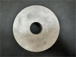
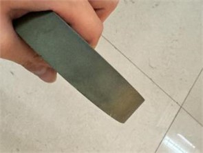
Table 1Actual measured values of the appearance and performance parameters of the closing resistor
Serial number | External diameter (mm) | Inside diameter (mm) | Thicknesses (mm) | Density (kg/m3) | Resistivity (Ω·m) |
1 | 127.14 | 34.40 | 25.33 | 2235 | 126.18 |
2 | 126.98 | 34.54 | 25.41 | 2252 | 120.11 |
3 | 126.64 | 35.21 | 25.32 | 2256 | 121.23 |
4 | 127.69 | 35.42 | 25.24 | 2250 | 120.32 |
5 | 127.21 | 34.82 | 25.37 | 2246 | 122.23 |
Average value | 127.132 | 34.878 | 25.334 | 2247.8 | 122.014 |
Standard deviation | 0.382 | 0.433 | 0.063 | 8.012 | 2.475 |
Standard uncertainty | 0.171 | 0.194 | 0.028 | 3.583 | 1.107 |
The closing resistors for 800 kV tank circuit breakers are high-voltage, non-inductive, carbon-ceramic linear resistors made up of fully mixed clay, alumina and graphite [15]-[18]. Carbon ceramic resistors are featured by sturdiness, durability, excellent heat transfer performance and excellent mechanical properties. An anti-leakage coating is added to the outer edge of the resistor to ensure its good tolerance [19]-[20]. From Table 2, it can be seen that the standard deviation and standard uncertainty of resistor density and resistivity are relatively large. This indicates that during the sintering process of the resistor, the control of the density consistency of the resistor is relatively weak, which also leads to significant fluctuations in the resistance of the resistor.
3. Experimental method
3.1. Thermal field emission scanning electron microscope
Carbon Ceramic Linear Resistors are made by fully mixing clay, alumina and graphite, and the content of each component, porosity, and the content of impurities all have an impact on its mechanical properties. The Quanta FEG 450 Thermal Field Emission Scanning Electron Microscope with an electron beam to scan the surface of the sample was used to study the surface morphology, chemical composition and other properties of the material. And the energy dispersive spectroscopy (EDS) attached to the microscope can be used to analyze the composition and content of resistor sheet. The acceleration voltage of the microscope ranges from 200 V to 30 kV, the probe current is adjustable up to ≤ 2 μA, and the magnification ranges from 20X to 106X.
3.2. Microhardness testing system
Hardness reflects the ability of a material to resist local plastic deformation and is an important index of mechanical property. Hardness measurement is to contact a hard object (indenter) of a certain shape and size with a certain pressure on the surface of the material to measure the resistance of the material in deformation process. In this paper, the fully automatic microhardness testing system (W1102D37) was used to test the hardness of the polished resistor sheet. The diamond square pyramid was used as the indenter. The angle between the two opposite sides of the regular square pyramid was 136°, and its bottom surface was square. The system’s test force ranged from 0.01 to 2 kgf; the maximum test height was 130 mm, with a throat depth of 175 mm. The test force accuracy was ±1.5 % for loads less than 200 g and ±1 for loads exceeding 200 g.
4. Results
4.1. Microstructure and composition of closing resistors
Fig 4 is a microscopic structure diagram of a closing resistor observed by a thermal field emission scanning electron microscope. It shows that the cross-sectional morphology of the closing resistor is a ceramic structure with aggregates, sintered clay binder, and pores evenly distributed. The surface crystallization is complete, and most of the ceramic grains are tens of μm in size.
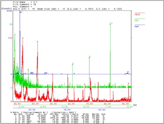
The composition and content of the closing resistor were analyzed using an energy dispersive spectrometer, as shown in Fig 5. The main components of the closing resistor are alumina ceramics, graphite and other impurities, of which oxygen elements account for about 59.2 % of the total mass fraction, aluminum elements account for about 34.6 %, silicon elements account for about 2.1 %, and carbon elements account for about 2.9 %. Therefore, the closing resistor is mainly made of alumina ceramics, and the proportion of graphite content is relatively small, but it forms an essential conductive path for the resistor. Alumina ceramics have excellent heat transfer and mechanical properties, which together ensure the safe and reliable operation of the resistor sheet.
Fig. 4Microstructure of closing resistance
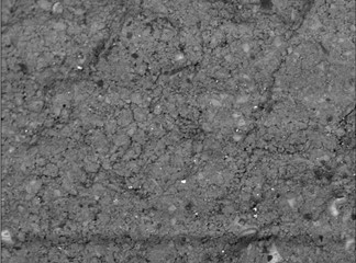
Fig. 5Content of each component of the resistor sheet
4.2. Vickers hardness measurement
In the microhardness test, the average value of the lengths of the two diagonals of the measured square pit is used to calculate the indentation area, and then the ratio of the load to the indentation area is calculated. The hardness represented by this ratio is the Vickers hardness, represented by HV.
The indentation area is:
Vickers hardness HV is:
where is the load, and the unit of which is N; is the diameter of the indentation; is the indentation area; and the unit of HV is GPa.
During testing, the closing resistor is ground and polished to ensure a flat and shiny surface, and then tested according to a hardness test stand. The test force was 0.2 kgf (1.96 N) and the loading time was 10 seconds. The hardness test was carried out at six locations in different directions of the same closing resistor at the same distance from the centre of the circle, and the test was repeated three times. Fig. 6(a) shows the micrograph of the hardness indentation on the surface of the resistor sheet, and Fig. 6(b) shows the Vickers hardness value of the resistor calculated according to Eq. (2).
Fig. 6Results of resistor sheet microhardness test
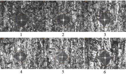
a) Hardness indentation on the surface of the resistor sheet
b) Hardness distribution on the surface of the resistor sheet
Fig. 6 shows that under the force of 0.2 kgf, no cracks appeared on the surface of the resistor sheet. According to the following formula:
The average Vickers hardness of the resistor sheet is 76.13 GPa, which standard derivation and standard uncertainty are 6.277 GPa and 2.807 GPa, respectively.
The microhardness of the interface area is a comprehensive reflection of the interface properties, including the size of the porosity, the change of the crystal’s average size, the level of the orientation index and the content of impurities mixed in the material. The microstructural features of the interfacial transition area are affected by many factors. The surface hardness of the resistor sheet varies slightly with the radial position. In the area near the outer edge the hardness decreases significantly, indicating that there is a weak interface area in the range of 5-15 mm from the surface of the material.
5. Simulation analysis
5.1. Model building
To obtain a stress distribution of the closing resistor of the circuit breaker which is much closer to actual opening and closing process, the physical field simulation software was usually employed in modern research. Importing the simplified model into the simulation software not only can obtain a much more accurate macroscopic stress distribution, but also clarifies the stress effect between different regions, which makes the mechanical characteristics of the closing resistor more direct and easier to analyze, and thereby greatly improving the accuracy of the conclusion [20].
Multiphysics software has multiple modules, which can perform single mechanical field analysis or multi-field coupling. It provides a pre-analysis method for equipment with which that cannot carry out specific experiments and observations, saving a lot of trouble. Since the operating conditions of specific equipment are often not affected by a single factor, multi physics simulation provides a good platform by combining a variety of physical studies to make the results more accurate [22].
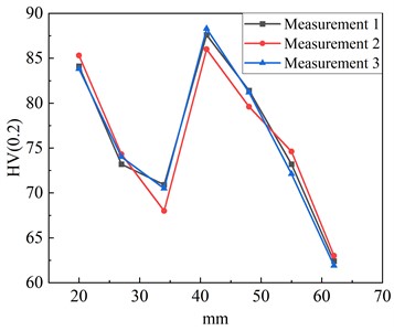
In this paper, the LW13-800 tank circuit breaker with closing resistor was used as a model, and the closing resistor stack was a 6-column series structure, as shown in the physical model in Fig. 7 and the simplified model in Fig. 8. Each column resistor sheet was assembled on the insulating rod in series. Both ends of the insulating rod were threaded structures. One end was directly connected to the connecting plate, and the other end was equipped with a spring, connecting plate and nut. When the nut was fastened to the insulating rod, the spring was compressed via the connecting plate, and the elastic force of the spring was applied between the resistor sheets to ensure reliable conduction between the resistors. After the 6-column resistor string was assembled, the connecting plate and the copper plate were connected in series, and then assembled on the flange of the arc extinguishing chamber through the insulating support.
Fig. 7The closing resistor stack
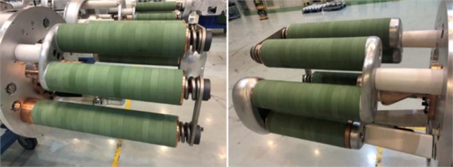
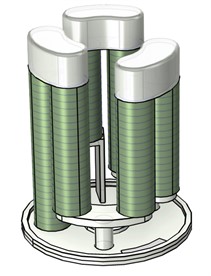
Fig. 8Simplified circuit breaker model
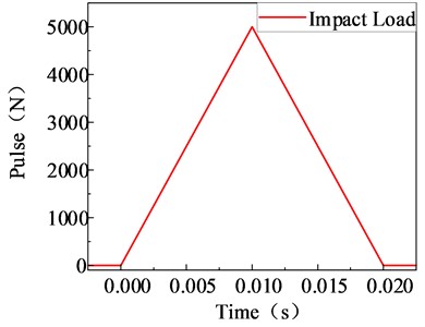
Under the actual working conditions, the upper end of the 6-column resistor sheet was connected to the spring in a compressed state. Under the working state, the upper end spring exerted a preload force of 5000 N downward to compress the resistance piece to avoid sliding or gaps. Meanwhile, the closing resistor was impacted by the contact in the opening and closing process, so an impact load was applied to the bottom area. The load was 5000 N, and the action time was 0.02 s, and the peak value appeared at 0.01 s. The impact load illustrated in Fig. 9.
5.2. Theoretical basis of mechanical analysis
5.2.1. Finite element method
This paper uses finite element analysis software, which calculates displacements, stresses, and strains in structures, therefore requires an understanding of the software’s solution theory. Since the finite element method is to decompose the structure into a finite number of small units to approximate the solution, its theoretical analysis is also built on the matrix equation again, and its specific solution equation is as follows.
Displacement of the unit:
where is the node displacement vector inside the cell, is a function of the displacement coordinates, is the displacement vector of the node, is the cell number.
Fig. 9Impact load distribution
Construct the equation:
By correlating the characteristic parameters of each small unit, the relevant characteristics of the whole structure under external load are calculated.
Geometric equations is:
Principal equation is:
where is the elastic strain component, is the elastic stress component, is the stiffness matrix, is the elasticity matrix.
Equilibrium equation:
The stresses in the entire structure are calculated by establishing the equilibrium equations for all nodes of the structure in the finite element, which are as follows:
where is the overall stiffness matrix, is the load matrix, is the displacement component. According to this equation, the stress distribution of each node can be found.
5.2.2. Theoretical analysis methods in mechanics
During the operation of the circuit breaker breaking and closing. The force on the closing resistor always corresponds to the time-varying load input to the operating mechanism during the opening and closing operations. And the inertial and damping forces in the input time-varying load cannot be neglected, therefore, when we calculate the equilibrium equation of time mechanics, we cannot ignore its inertia force, which generates the following force equilibrium equation:
where is the structural mass matrix, is the damping matrix, is the stiffness matrix, is the generalized force vector, is the generalized coordinate vector. The above equations can be used to establish the equilibrium equation of the force of the closed resistor sheet under the action of shock and solve the stress distribution.
5.3. Mechanical simulation results
5.3.1. Mechanical analysis of a single resistive sheet
As mentioned above, when the resistor string was assembled, the resistor sheet was pressed on the connecting plate by the elastic force of the spring. According to the requirements of the drawing, when the spring was compressed to the required size, the elastic force was about 5000 N, i.e., in normal assembled state, the end face of each resistor sheet bore this pressure. Moreover, after the assembly of the resistor stack was completed, the gravity of the entire assembly was loaded on its mass center. According to this boundary condition, the static analysis of the resistor assembly was carried out. It focused on the stress state of the resistor sheet closest to the fracture position of each resistor string. The load application and simulation results are shown in Fig. 10 and Fig. 11.
Fig. 10Impact load
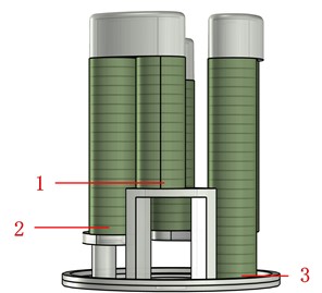
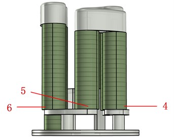
Fig. 11Simulation results
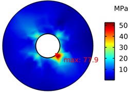
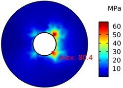
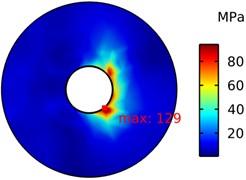
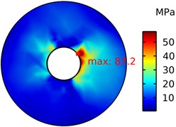
The results show that when the closing resistor is assembled under the pressure of the spring and its own gravity, the locations where the maximum stress of the closing resistor appears are all located near the inner prongs, of which the maximum stress near the inner prongs of the No. 5 closing resistor is 129 MPa, and the maximum stress exceeds the permissible stress, and there is a risk of breakage of the closing resistor. This paper concludes that the cause of the stress concentration phenomenon in the inner prong of the closing resistance is mainly due to the fact that there is a hard contact between the inner prong of the closing resistance and the contact position of the insulating rod, and the collision in the process of switching and closing makes the inner prong position to have a phenomenon of extrusion and collision.
5.3.2. Mechanical analysis of a resistive sheet with an uneven surface
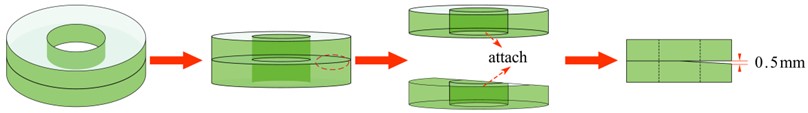
It is difficult to ensure the absolute smoothness of resistor sheet’s surface in processing process. Dismantling and inspecting the faulty resistor sheet showed that there were obvious friction marks on the surface of a large number of resistor sheets, and there were two bright areas on the two sections of the broken resistor sheet, which were due to the friction between two adjacent sheets. Therefore, the flatness tolerance of the resistor sheet had a certain effect on the rupture of the resistor sheet. It was verified by means of simulation. For calculation convenience, the model was simplified, and only the stress distribution between the two resistor sheets was concerned. The upper and lower resistor sheets were loosely connected in series through the insulating rod with a 0.5 mm gap between them, and only one side of them was closely appressed. The simplified model is shown in Fig. 12.
Fig. 12Simplified model
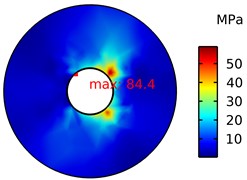
A fixed constraint was imposed on the bottom, and the magnitude of the impact load was unchanged. With the top pressing force 5000 N unchanged, the stress distribution of the lower and upper resistor sheets is shown in Fig 13.
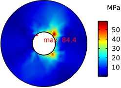
Fig. 13The stress distribution of the lower and upper resistor sheets
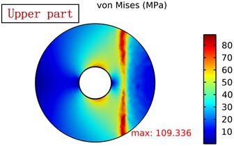
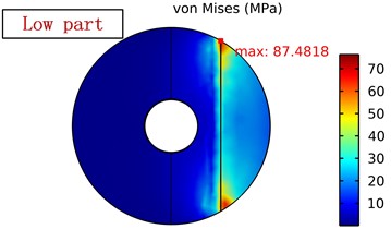
The results show that, when the surface of the closing resistor is not completely smooth, the position of the contact surface of the closing resistor due to friction and other reasons will lead to the contact part of the stress concentration, and the location of the maximum stress gradually to the transition near the outer edge, when the degree of unevenness of 0.5 mm, the maximum stress is close to the permissible stress, accompanied by the role of the cause of material ageing, the closing resistor there is a risk of breakage. In the field operation of the broken closing resistor recovery observation found that the closing resistor contact surface unevenness caused by the form of breakage and the field breakage form in line with.
6. Conclusions
In this paper, multi-physics simulation software was used to analyze the mechanical characteristics of the closing resistor of 800 kV high-voltage circuit breakers, and the following conclusions were obtained.
1) The main component of the resistor sheet is alumina ceramics, and the mass proportion of carbon element is small, which is 2.9 %; the average Vickers hardness of the resistor sheet is 76.6 GPa. The surface hardness of the closing resistor varies slightly along the radius. Especially in the area around the inner and outer edges of the resistor, the hardness decreases significantly. This phenomenon is due to changes in the structural density of the material in the vicinity of the inner and outer edges of the resistor within a radius of approx. 5-15 mm or to the uneven distribution of fillers and adhesives during the manufacturing process.
2) Under the condition of no impact, when the surface of the closing resistor is in good contact, although stress concentration occurs on some resistor sheets of the resistor stack, it does not reach the maximum allowable stress and meets the design requirements.
3) Under normal impact conditions, when the surface of the closing resistor is in good contact, a large stress appears on the outer and inner edges of the resistor sheet. The gap between the inner edge of the closing resistance and the insulating rod is small, under the action of the impact load, it is easy to produce collision and friction, resulting in the maximum stress of the inner edge of the inner prism is larger than the outer prism.
4) Under normal impact conditions, when there is a gap in the surface of the closing resistor, the maximum stress at the contact position of the closing resistor is transferred from the inner prong to the outer prong, and the location where the maximum stress occurs corresponds macroscopically to the breakage position of the actual broken closing resistor in the field.
In this paper, the maximum stress on the closing resistance is only considered in the simulation of opening and closing impact load, and the transfer process of the stress wave between structures is not considered, which is incomplete compared with the actual situation, and a more in-depth study should be carried out on the basis of this.
References
-
X. Han et al., “The overview of development of UHV AC transmission technology in China,” (in Chinese), Chinese Journal of Electrical Engineering, Vol. 40, No. 14, pp. 4371–4386, 2020, https://doi.org/10.13334/j.0258-8013.pcsee.182251
-
H. Heiermeier and R. Raysaha, “Power testing of preinsertion resistors: limitations and solution,” 2017 IEEE Manchester PowerTech, Vol. 32, No. 4, pp. 1688–1698, Jun. 2017, https://doi.org/10.1109/ptc.2017.7980971
-
T. Lazimov, E. A. Saafan, and N. Babayeva, “Transitional processes at switching-off capacitor banks by circuit-breakers with pre-insertion resistors,” in Modern Electric Power Systems (MEPS), Jul. 2015, https://doi.org/10.1109/meps.2015.7477204
-
X. Ma, “Fault analysis of 750 kV circuit breaker breakdown based on multi-physical field simulation,” (in Chinese), Ningxia Electric Power, pp. 27–33, 2023.
-
K. Liu et al., “Stress distribution numerical simulation and influencing factor analysis of stress under operating shock of pre-insertion resistor of 750 kV dead tank circuit breaker,” (in Chinese), High Voltage Apparatus, Vol. 59, No. 8, pp. 180–185, 2023, https://doi.org/10.13296/j.1001-1609.hva.2023.08.021
-
J. Xie, S. Zhang, and J. Li, “Analysis on a closing resistor failure of tank circuit breaker in a 750 kV substation,” (in Chinese), Electric Safety Technology, Vol. 24, No. 7, pp. 58–61, 2022.
-
B. Niu et al., “Fault analysis of pre-insertion resistors for 800 kV circuit breakers in AC filters field,” (in Chinese), High Voltage Apparatus, Vol. 56, No. 7, pp. 36–43, 2020, https://doi.org/10.13296/j.1001-1609.hva.2020.07.006
-
F. Ma et al., “Fault analysis of circuit breaker’s closing resistor for 750 kV AC filter,” (in Chinese), Power Capacitor and Reactive Power Compensation, Vol. 40, No. 4, pp. 145–151, 2019, https://doi.org/10.14044/j.1674-1757.pcrpc.2019.04.025
-
Y. Bao, K. Liu, D. Wen, Y. Li, H. Wang, and H. Zhang, “Electrical-thermal coupling characteristics of pre-insertion resistors in AC filter circuit breaker for UHV grid,” Mathematical Biosciences and Engineering, Vol. 20, No. 7, pp. 12056–12075, Jan. 2023, https://doi.org/10.3934/mbe.2023536
-
J. Liu, “Mechanical characteristic testing and status evaluation of sf6 high-voltage circuit breaker,” (in Chinese), High Voltage Apparatus, Vol. 56, No. 6, pp. 173–180, 2020, https://doi.org/10.13296/j.1001-1609.hva.2020.06.025
-
Z. Zhao, J. Guo, F. Yu, X. Rao, and X. Wu, “Study on working condition of 750 kV AC filter breaker in ± 1100 kV UHVDC system,” The Journal of Engineering, Vol. 2019, No. 16, pp. 839–844, Nov. 2018, https://doi.org/10.1049/joe.2018.8410
-
B. Niu, F. Ma, S. Sun, and Y. Xu, “Research on operation and fault diagnosis technology for EHV/UHV SF6 circuit breakers pre-insertion resistors,” Elsevier BV, Energy Reports, Nov. 2021.
-
K. Chen et al., “Working principle and testing technology of circuit breaker closing resistor for 1100kV GIS,” in IOP Conference Series: Earth and Environmental Science, Vol. 330, No. 5, p. 052006, Oct. 2019, https://doi.org/10.1088/1755-1315/330/5/052006
-
M. A. Haseeb and M. J. Thomas, “Disconnector switching induced transient voltage and radiated fields in a 1100 kV gas insulated substation,” Electric Power Systems Research, Vol. 161, pp. 86–94, Aug. 2018, https://doi.org/10.1016/j.epsr.2018.04.001
-
F. Lupone, E. Padovano, O. Ostrovskaya, A. Russo, and C. Badini, “Innovative approach to the development of conductive hybrid composites for Selective Laser Sintering,” Composites Part A: Applied Science and Manufacturing, Vol. 147, p. 106429, Aug. 2021, https://doi.org/10.1016/j.compositesa.2021.106429
-
Y. Zhang et al., “Exploration on the characteristics of new ceramic materials for insulators used in SF6 gas insulated HVDC equipment,” (in Chinese), Chinese Journal of Electrical Engineering, Vol. 41, No. 1, pp. 174–182, 2021, https://doi.org/10.13334/j.0258-8013.pcsee.201870
-
X. Cai and P. Feng, “Reaction mechanism and oxidation resistance at 700-900 °C of high porosity NiAl intermetallic,” Corrosion Science, Vol. 191, p. 109731, Oct. 2021, https://doi.org/10.1016/j.corsci.2021.109731
-
A. Bondar, I. Iordache, and P. Svasta, “Carbon/ceramic composites designed for electronic application,” in 1st Electronic Systemintegration Technology Conference, pp. 708–713, Jan. 2006, https://doi.org/10.1109/estc.2006.280089
-
T. A. Mohammed and S. Abebe, “Numerical investigation of steel-concrete composite (SCC) beam subjected to combined blast-impact loading,” Heliyon, Vol. 8, No. 9, p. e10672, Sep. 2022, https://doi.org/10.1016/j.heliyon.2022.e10672
-
J. Y. Huang, J. C. Yuan, T. T. Zhu, T. Zhong, Y. F. Xu, and S. N. Luo, “Dynamic compressive strength of alumina ceramics,” Ceramics International, Vol. 48, No. 24, pp. 36371–36382, Dec. 2022, https://doi.org/10.1016/j.ceramint.2022.08.196
-
M. Marin, A. Hobiny, and I. Abbas, “The effects of fractional time derivatives in porothermoelastic materials using finite element method,” Mathematics, Vol. 9, No. 14, p. 1606, Jul. 2021, https://doi.org/10.3390/math9141606
-
A. D. Hobiny and I. A. Abbas, “Nonlinear analysis of dual-phase lag bio-heat model in living tissues induced by laser irradiation,” Journal of Thermal Stresses, Vol. 43, No. 4, pp. 503–511, Apr. 2020, https://doi.org/10.1080/01495739.2020.1722050
About this article

The authors have not disclosed any funding.
The datasets generated during and/or analyzed during the current study are available from the corresponding author on reasonable request.
Yanyan Bao: conceptualization, methodology, writing-original draft preparation, writing-review and editing. Kang Liu: data curation, formal analysis, investigation, project administration, resources, software. Feng Wang: supervision, validation, visualization.
The authors declare that they have no conflict of interest.
