Abstract
Water-lubricated bearings are pivotal components in ship propulsion shafting, The mechanical properties of composite materials serve as the foundation for water-lubricated bearing materials. In this paper, taking the 3D composite structure material of arthropod outer carapace as a biological model, a bionic design of a water-lubricated bearing composite material based on rigid and flexible substances coupled with microstructure is proposed, and its load-carrying properties are analyzed through simulation and experimentation. The research results showed that the rigid fiber helix angle of 30° would be better for enhancing mechanical performance. When the basic parameters of the RVE (representative volume elements) are determined, the arrangement of it will also affect the mechanical properties of the composite material to a certain extent, and from the test results, the three RVEs combination mode can obtain better bearing capacity.
1. Introduction
Compared with traditional stern bearings, water-lubricated bearings have many advantages of pollution free, impact resistance, vibration and noise reduction performance, but it also has low carrying capacity caused by low viscosity of water and poor lubrication caused by the grooves design [1, 2]. Therefore, it is necessary to carry out more in-depth research on bearing structure design and material selection to improve the strength and toughness [3, 4].
Water-lubricated bearing composite material is a development hotspot at present. Wang [5] added various nano-powders to NBR to study its mechanical and tribological properties, and the test results showed that the performance of this material was better than that of NBR. Yu [6] used polyether ether ketone and carbon fiber as rigid reinforcement materials and bonded with polytetrafluoron as matrix material to prepare a new type of water-lubricated bearing material. Based on SPA material, Duramax Marine [7] developed a new type of polymer alloy water-lubricated bearing material, which optimizes bearing capacity. Wang [8] reduced the “edge effect” of traditional water-lubricated tail bearings by adding a thin layer of damping on the outside of the bearing bushing.
In recent years, bionic design and porous structure have gradually become one of the main methods to improve the wide-band vibration and noise reduction of engineering materials. However, there are still few bionic studies on water-lubricated bearing materials. In nature, the biological structure of mantis shrimp, beetle, lobster and other arthropods is characterized by high strength and light weight [9]. Compared with single structure composite materials, the typical structure of biomimetic composite materials mainly includes hierarchical structure [10], spiral structure [11, 13], gradient structure [14], layered structure [15] and pore structure. These structures give biomaterials superior mechanical and impact properties. Thomas et al. [16] studied beetles and found that their fiber arrangement was helical. They used glass fibers to prepare helical fiber laminates and verified their excellent mechanical properties through mechanical tests. Zhao used 3D printing technology to test the mechanical properties of the fabricated biomimetic structures with different helical angles, and found that lower single-layer helical angles could improve isotropy and enhance structural toughness. Chen Bin [17] studied the epidermal structure of chafer beetle and found that there was a honeycomb lamellar structure in its outer carapace, which could not only stop cracking but also reduce the density of the material and effectively enhance the strength and toughness of the outer cortex of chafer beetle.
In general, it is an innovative idea worth promoting to use these biological models for bionic design of water-lubricated bearing materials. Focusing on the structure and material of water-lubricated bearing and based on the anterior epidermis of arthropod outer carapace from the biomimetic perspective, the bionic design of rigid and flexible heterogeneous coupled with microstructure is created for water-lubricated bearing materials. Finally, through the compressive deformation behavior study of this bionic material in this paper, a new idea for the preparation of water-lubricated bearing materials with high strength and high toughness is provided.
2. Bionic design
This paper proposed a new bionic structure based on the outer carapace of the American crayfish. According to the microscopic analysis, the fiber structure layer composed of rigid and flexible heterogeneous materials is parallel to the surface of the outer carapace and contains oval holes. The fiber layer rotates along the normal direction of the outer carapace plane to form a layered spiral structure, which is called the Bouligang structure and constitutes three epidermal structural layers of the outer carapace [18]. The Bouligang structure could not only provide good support but also eliminate partial external impact energy. In addition, this structure presents low density for its reticular microstructure.
Fig. 1Schematic diagram of bionic design process
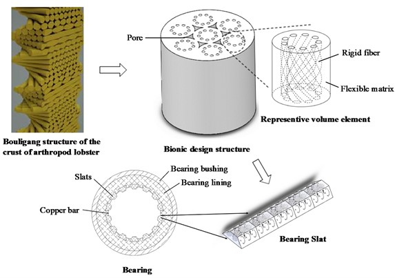
According to the performance requirements of the water-lubricated bearings, a simplified bionic structure is designed as shown in Fig. 1. The bionic structure model includes rigid helical fiber structure and flexible matrix. which contains a plurality of cylindrical representative volume elements (RVE), with spiral fiber set in each RVE. The multiple spiral fibers are rounded into a circle and the arrangement direction is perpendicular to the material surface. The fiber and the surrounding matrix constitute a RVE. Multiple RVEs are enclosed to form a periodic mesoscopic structure, with the gap distribution between the RVEs forming a beehive-like structure. The strip helical fibers were designed with constant or variable pitch, and the helical angle could change gradient, thus the pseudo-bouligang structure is formed. The bionic design carried out in this way can provide light weight, high strength and high toughness for the design of water-lubricated bearing materials. Generally, the bionic structure is distributed in the axial direction and radial direction of bearing slats by gradient, which can design water-lubricated bearings suitable for specific working situations.
3. Analysis
3.1. Theoretical considerations
Mesoscopic mechanics method is one of the main methods for analysis of composite material mechanics behavior. Its principle is through the establishment of the macroscopic properties of the composite and the quantitative relationship between mesoscopic parameters, that is the representative methods or expression for the overall physical performance parameters of the composite, set up theoretically based on the physical properties of component materials and the way of interaction, the reinforced fiber and matrix are regarded as homogeneous materials with different properties and as RVE. Then, through the analysis of fiber volume fraction, distribution mode, matrix properties and the interaction between them, the macroscopic mechanical properties of materials are predicted to provide a basis for the study of its deformation mechanism [19].
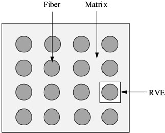
Representative tissue units are selected according to the geometric features of the mesostructure of the composite material, and the composite material is formed by periodic expansion of RVEs [20], as shown in Fig. 2. RVE is the main research subject in the mesoscopic study of composite materials, so, through the mesomechanical study and analysis of RVE, the homogeneous load boundary conditions are applied to simulate the deformation of composite materials under the action of load.
Fig. 2Periodic mesostructure and RVE
3.2. Simulation of compression deformation
RVE is widely used to simulate the dynamic behavior of composites with complex 3D structures. In the process of loading, as for the RVE of the biomimetic composite material designed in this paper, most of the load is carried by rigid fibers, and the flexible matrix allows the stress to be transmitted through the shear process and distributed more evenly to all fibers. In this paper, widely used water lubricated bearing material nitrile rubber is selected as the flexible matrix of the RVE, and carbon fiber with high modulus as the rigid fiber part. The material properties are shown in Table 1.
Table 1Properties of the RVE
Elastic modulus (MPa) | Poisson’s ratio | |
Carbon fiber | 2.1×10⁵ | 0.307 |
Nitrile rubber | 6.1 | 0.49 |
The helical angle of rigid fibers is an important parameter in the bouligang structure of bionic design. Seven biomimetic structures designed with different helical angle of rigid fiber structures were designed, as shown in the Table 2. Each fiber diameter is 1 mm and the height of RVE is 10 mm.
Table 2Helical angle of rigid fiber structures
S.N. | Angle | S.N. | Angle |
1 | No | 5 | 30° |
2 | 0° | 6 | 40° |
3 | 10° | 7 | 50° |
4 | 20° |
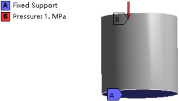
In the simulation analysis, 1 MPa surface load is applied perpendicular to the top surface of the RVE. It is assumed that the bond interaction between the tail end of the fiber and the flexible matrix makes the bottom end of the rigid spiral fiber not twist, so the bottom degrees of freedom of the fiber and the matrix are constrained, as shown in Fig. 3.
Fig. 3Settings of simulation analysis
3.3. Compression test
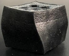
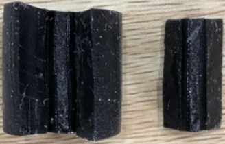
The pore distribution between RVE is another important parameter of bionic structure. Based on the analysis of the helical angle of the bionic structure, two samples, as shown in Fig. 4, with different pore distribution patterns were prepared by 3D molding technology and the better angle from the results of simulation, and the mechanical properties of the samples were analyzed by auniversal testing machine.
Fig. 4Compression test specimen
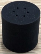
a) Three RVEs assembly
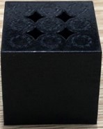
b) Four RVEs assembly
Three RVEs Assembly is a combination of three volume units with smaller pores between the units, while Four RVEs Assembly is four volume units with larger pores. The rigid fiber material of the RVE is nylon glass fiber with strength of 3500 MPa and diameter of 1mm. The flexible matrix material is nitrile rubber with strength of 5 MPa.
In the compression test, the sample is placed in the central position of the pressing plate of the universal testing machine, and the pressing plate is flat and smooth, and the pressing plate is parallel to the surface of the sample in a state of just contact, as shown in Fig. 5. The model is destroyed or its height is reduced to a predetermined value by compression along the axial direction, the direction of fiber extension, of the model at a constant rate, typically 2 mm/min. During the test, the load on the model and the height of the model or its strain variables are measured, and the compressive stress and compressive elastic modulus of the composite model are measured and calculated.
Fig. 5Schematic diagram of compression test
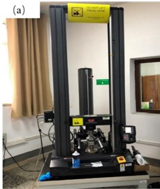
a) Universal testing machine
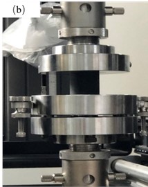
b) Loading part
4. Results and discussion
4.1. Simulation results
In the process of analysis, it is necessary to refine the mesh where the load is applied and where the rigid and flexible materials meet, so that the mesh division quality is above 0.8. The compressive deformation simulation analysis results of the seven RVEs in Table 2 under the same boundary conditions are shown in Table 3.
From the simulation results, it can be concluded that after adding carbon fiber, the bearing capacity of the composite material is greatly improved compared with the pure flexible matrix material, meanwhile, the compressive performance is improved, and the overall mechanical properties of the material is also improved.
With the increase of the helical angle, the deformation of both matrix and fiber increases slowly, but the stress of matrix decreases gradually, while the stress of fiber increases first and then decreases. The maximum stress value is obtained when the helical angle is 30°. Therefore, a helical angle of 30° can provide higher compressive strength.
4.2. Compression test results
The compression load was set to 90 % of sample height, and the damage effect and deformation mechanism under compression load was analyzed.
(1) Compressive stress-strain curve. As can be seen from Fig. 6, the compression stress of both arrangements present exponential growth with strain. The compression process can be divided into two stages: large deformation stage and small deformation stage. In large deformation stage, the elastic matrix first absorb load, the internal pores in the sample are compressed. Therefore, the macroscopic elastic modulus of the sample is relatively small. With the increasing compressive load, the material density will increase that lead to rapid stress increase, namely the stage of small deformation. At this stage, the elastic matrix and the rigid fiber support load together. The cross section of the sample get larger and larger, but the increment of stress is larger than the increment of strain. This indicates that the rigid fiber has been supporting most load. Thus, this bionic design can provide better bearing performance for water-lubricated bearing materials.
Table 3Results of deformation and stress
Fiber angle | Flexible matrix | Rigid fiber | ||
Deformation (mm) | Stress (MPa) | Deformation (mm) | Stress (MPa) | |
No | 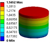 | 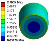 | ||
0° | 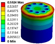 | 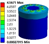 | 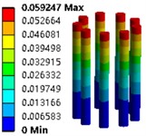 | 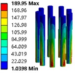 |
10° | 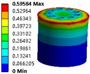 | 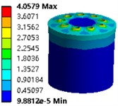 | 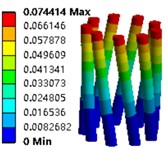 | 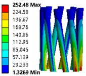 |
20° |  | 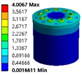 | 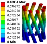 | 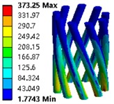 |
30° | 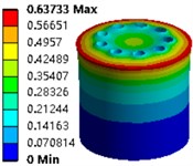 | 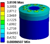 | 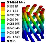 | 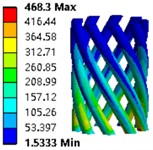 |
40° | 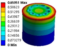 | 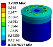 | 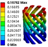 | 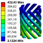 |
50° | 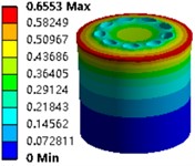 | 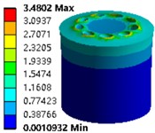 | 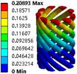 | 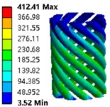 |
Fig. 6Compressive stress-strain curve
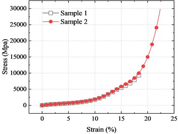
a) Three RVEs assembly sample
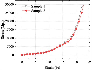
b) Four RVEs assembly sample
(2) Compressive strength and elastic modulus. According to the compression calculation method, the compression strength and elastic modulus of the tested data were calculated as follows:
where σc is compressive stress, Ec is elastic modulus, P is the maximum load, F is the cross-sectional area of the sample, ε is strain, L is the height before compression, ΔL is the deformation amount of the sample.
The calculation results of the test data of the two samples are shown in Table 4.
Table 4Test data calculation results
Maximum load (N) | Cross-sectional area (mm2) | Compressive stress (MPa) | Deformation amount (mm) | Elastic modulus (MPa) | |
Three RVEs | 29847 | 0.307 | 35.9 | 23.5 | 0.038 |
Four RVEs | 29591 | 0.49 | 28.0 | 23 | 0.050 |
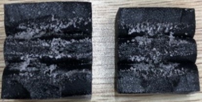
(3) Damage type. Remove the compression load after 90 % height compression has been reach. The two samples after elastic recovery are shown in Fig. 7.
Fig. 7Damage status
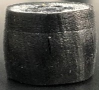
a) Three RVEs assembly
b) Four RVEs assembly
There are obvious powdery substance on the top surface of the two samples, while the side surface are relatively integrated. After unloading, the three RVEs presents slightly convex in the middle, while the four RVEs presents a torsion form. This is because the pore size of the four RVEs is larger than that of the three RVEs. After with high load, irrecoverable distortion has occurred under the guidance of the rigid fiber.
The specimens have been hardened after compression test. Shear failure is the mainly failure mode so that the fiber buckling makes them detach from the surrounding matrix. When the load further increased, the fibers begin to distort and extrude the matrix, resulting in cracks inside the composite. With the load exceeding the yield limit, the cracks begin to expand rapidly from inside to outside until the surface of the matrix material cracks. In order to further analyze the compression deformation state of the two structural modes, the samples were cut and the internal morphology was observed. The topography photos are shown in Fig. 8.
Fig. 8Internal topography
a) Three RVEs assembly
b) Four RVEs assenmbly
The internal morphology showed that the internal element of the three RVEs is still stable, and the internal friction and shear deformation are smaller than those of the four RVEs. Instead, the internal element of the four RVEs has been deformed with cracks and burrs appearing, and the rigid fibers have been broken. This situation indicates that the pore size between RVE should not be too large, which has too much influence on the stability of the biomimetic structure.
5. Conclusions
In this paper, taking the outer shell of lobster as the biomimetic object, a water-lubricated bearing biomimetic composite material coupled with rigid and flexible heterostructure is proposed. Then the related finite element analysis of the deformation of the material is carried out. On this basis, the specimens were prepared by 3D printing. Lastly, the compression mechanical properties were tested. The conclusions are as follows:
1) The helical angle of rigid fibers significantly influences the mechanical properties of biomimetic structures. Simulation results demonstrate that a helical angle of 30° yields superior compressive strength.
2) The distribution of pores within microstructures serves as another crucial parameter impacting the mechanical properties of biomimetic structures. Experimental findings reveal that a combination mode incorporating three representative volume elements (RVEs) achieves enhanced bearing capacity.
3) The design of biomimetic structures, integrating rigid and flexible heterostructures with microstructures, proves to be effective in enhancing the comprehensive mechanical properties of composites.
References
-
S. Wu, “Lubrication performance and thermal structure coupled analysis of water-lubricated rubber alloy slab bearings,” Chongqing University, Chongqing, 2011.
-
Y. Jin et al., “Feature recognition on friction induced vibration of water-lubricated bearing under low speed and heavy load,” Journal of Marine Science and Engineering, Vol. 11, No. 3, p. 465, Feb. 2023, https://doi.org/10.3390/jmse11030465
-
X.-R. Zhou, “Experimental study on friction and wear of nano-sized molybdenum disulfide water-lubricated rubber-plastic stern bearings,” Wuhan University of Technology, Wuhan, 2017.
-
K.-J. Wu, “Multiscale mechanical design of high-performance structures inspired by “spear and shield”-type biological competition,” University of Science and Technology of China, Hefei, 2021.
-
J.-X. Wang, Z. Chen, and D.-T. Qing, “Study on friction properties of water lubricated plastic bearing,” Mechanical Engineering Materials, Vol. 11, pp. 36–38, 2002.
-
H.-L. Yu, “Experimental research on marine pump water lubrication bearing lubricating performance,” Shanghai Jiao Tong University, Shanghai, 2012.
-
R. L. Orndorff and R. C. Spangler, “SPA super demountable bearing,” US6648510 B2, 2003.
-
M.-X. Wang, “FE simulation and calculation of water lubricated damping stern bearing,” Ship Standardization Engineer, Vol. 5, pp. 53–56, 2013.
-
H.-L. Qin, “Study on mechanical properties of biomimetic laminated structural fiber composites,” Jilin University, Changchun, 2020.
-
J. A. Kluge, O. Rabotyagova, and G. G. Leisk, “Spider silks and their applications,” Trends in Biotechnology, Vol. 26, No. 5, pp. 244–251, 2008.
-
T. Lenau and M. Barfoed, “Colours and metallic sheen in beetle shells – abiomimetic search for material structuring principles causing light interference,” Advanced Engineering Materials, Vol. 10, No. 4, pp. 299–314, 2010.
-
D. Ebenstein, C. Calderon, and O. P. Troncoso, “Characterization of dermal plates from armored catfish pterygoplichthys pardalis reveals sandwich-like nanocomposite structure,” Journal of the Mechanical Behavior of Biomedical Materials, Vol. 45, pp. 175–182, 2015.
-
J. C. Weaver et al., “The stomatopod dactyl club: a formidable damage-tolerant biological hammer,” Science, Vol. 336, No. 6086, pp. 1275–1280, Jun. 2012, https://doi.org/10.1126/science.1218764
-
P. Y. Chen, J. Schirer, and A. Simpson, “Predation versus protection: fish teeth and scales evaluated by nanoindentation,” Journal of Materials Research, Vol. 27, No. 1, pp. 100–112, 2012.
-
R. Menig, M. H. Meyers, and M. A. Meyers, “Quasi-static and dynamic mechanical response of haliotis rufescens (abalone) shells,” Acta Materialia, Vol. 48, No. 9, pp. 2383–2398, 2000.
-
L. Cheng, A. Thomas, and J. L. Glancey, “Mechanical behavior of bio-inspired laminated composites,” Composites Part A, Vol. 42, No. 2, pp. 211–220, 2011.
-
B. Chen, “Study on microstructures and biomimetic composites of biological composites,” Materials Review, Vol. 12, No. 5, p. 70, 1998.
-
I. Etsion, “State of the art in laser surface texturing,” Journal of Tribology Transactions of the ASME, Vol. 127, No. 1, pp. 248–253, 2005.
-
K. Liu, “Research on elastic property prediction and failure behavior of 2D-C/SiC composites,” Dalian University of Technology, Dalian, 2021.
-
Y.-X. Duan, H. Yang, and Y. Zhuo, “Model for short fibre reinforced rubber material,” China Synthetic Rubber Industry, Vol. 43, No. 3, pp. 186–191, 2020.
About this article

The authors give sincere thanks to the editors and the reviewers for their patient work and constructive suggestions. This work is supported by the State Key Program Grant of Natural Science Foundation of China (No. 51071244).
The datasets generated during and/or analyzed during the current study are available from the corresponding author on reasonable request.
Ruiqing Li: writing-review and editing; Yong Jin: conceptualization. Wu Ouyang: project administration. Jian Huang: methodology. Shuang Sun: writing-original draft preparation. Bin Luo: formal analysis.
The authors declare that they have no conflict of interest.
