Abstract
Through the description of the methodology of the development of a bite force measurement device it will be shown how interdisciplinary work of Engineers and Health Professionals bring enhance of life quality to general population. Bite force measurement is a reliable exam to check stomatognathic system (SS) conditions. In order to provide a reliable, low cost and do-it-yourself gnathodynamometer a Dentist joined Bioengineering Laboratory (LabBio) at UFMG. The development of a 3D printed resin structure was made using CAD/CAM and tested by means of FEM. A Carbon Nano Tube (CNT) extensometer developed at CTNANO at UFMG to capture the structure deformation were fixed in two geometries that showed good results in FEM simulation and will be tested in an EMIC universal mechanical testing machine (DL1000) equipped with a 1 kN load cell. The electrical response of the extensometers was monitored using a Keithley 2000 digital multimeter (Tektronix), connected to a computer and remotely controlled by a LabView application (View Point Systems), a data storage protocol in a SD card and in the clouds using IoT and an data acquisition system will be tested. In bench tests both geometries showed good results with deformation capturable from 40 N. Data was codified using an Arduino Nano and a program was developed for data acquisition and storage. The interdisciplinary work generates prototypes with promising results in bench tests. The fruit of the team work may generate a toll that improves life quality of population by allowing more people to be tested and lowering health costs.
1. Introduction
Bite force is a key element for the survival of most animal species, including the human species. The bite is used as a defense and attack weapon, and for obtaining, cutting, and chewing food and influences craniofacial morphology [1-7]. With the softening of food feeding habits, even feed time changed for humans who live in big centers [2].
Bite force measurement is a noninvasive, non-infiltrative and non-ionizing test that provides reliable information that can be used to verify the functional conditions of the stomatognathic system (SS) relevant to clinical dental and general health conditions, quality of life, research, anthropology, phylogenetic knowledge and development of new materials and technologies [2, 8-34]. The measurement of individual’s bite force generates data about the his/her grinding capacity. The higher the bite force, higher the grinding capacity and higher is the mastication efficiency [35] what impact aging quality of life [14, 32] among other things. Eating habits may be simultaneously associated with the development of masticatory function, nervous system development and cardiovascular rhythm [36].
The existing gnathodynamometers on the market have a high cost, making it difficult for emerging countries to acquire them. The vast majority of bite force measurement devices are sold in American Dollars or Euros, which, with the unfavorable exchange rate in developing countries, raises the price and the difficult to acquire in private practices. Another point is importing taxes, raising more the prices and the customs bureaucracy. For instance, in Brazil there is only one manufacturer of bite force meters, for such the accessibility to the devices is not easy for use in most dental offices and public health services. Moreover, some of them are difficult to transport due to the peripherals necessary to record the data obtained in the bite force tests, the size and weight of the dispositive, number of cases need and so on, thus compromising their use in public health services, particularly those that serve communities far from and/or isolated from the larger cities. For such an on-board system of data obtained in the bite tests recording and saving is crucial to ease transport.
The Suita health program in Japan uses bite force measurements to control population aging quality of life using pressure films. For instance, the 50 type R manufactured by Fujifilm Corp needs a special scanner (Occluser FDP-703) also manufactured by Fujifilm Corp [37]. Three major problems arise from this: the raise in cost, the difficult to transport the pressure films to be read in the scanner of transport the scanner to read the pressure films in loco, and the difficulty of transport raises to. If the pressure films receive load during transportation a bias was created.
Another point that took the team to develop the dispositive to measure human bite force is the public dental health care in Brazil that is poor for many reasons that are not in the scope of this work but one has to be highlighted. There is the role health agent in Brazilian health care, but this individual does not have, and is not in its obligations, a proper dental training that allows him to diagnose a lot of stomatognathic system problems and diseases what brings a worse prognosis to the patient when diagnosed and increases the costs of publica health system. With an easy to transport device he will be able to detect oral problems early contributing to better prognosis treatment and lowering of costs to the public health system. It is always good to explain that Brazil has very distant and poor districts that the health agent visits from time to time, lots of people living in very small communities in the rural zone. To test these individuals the dispositive must be light and easy to transport. The test itself is simple and the reading of the results is simple too, allowing the health agent with minimal training to perform the bite force tests.
Based on this, we have endeavored to develop a low-cost device using CAD/CAM and nano technology to develop and manufacture the geometry of the device, especially, the part of the gnathodynamometer that will be bitten, hereinafter referred to as the bite tip. Computational simulation by Finite Element Method (FEM) was used to test the deformation pattern of the bite tip before printing it with a 3D printer and performing bench tests to determine the best region (with greater sensitivity) in which to assemble the extensometer, and its best position.
To provide an easier way to transport and work with the gnathodynamometer, data will be sent to the cloud. This facilitates the use of the gnathodynamometer in public health, especially when acquiring data in distant and or isolated communities. In the Brazilian public health service, the technical position of Health Agent has been implemented. These Agents visit people’s home to check their health conditions. In case of doubts or any symptoms, they first send the people to the nearest health posts and, if necessary, to hospitals.
Fundamental conditions for the gnathodynamometer, (especially for the bite tip) are: absence of edges that can cause damage, made of nontoxic material that does not deform, lose its physical properties or stability during the disinfection process, deforms in a way that can be captured with precision when applying pressures from 40 N to 1 kN to capture the lower bite force (in incisive in children) [20] and the highest (in molars in adults) [38]and does not fail, fracture or lose its properties under these pressures.
For measurement of the bite force, the bite tip must be inserted into several regions in the mouth, depending on the investigation. Therefore, the bite tip should have a functional topography and its thickness must not exceed 10 mm due to the risk of compromising the data obtained [8].
The need to develop the dispositive require expertise of professionals of different areas. To develop the geometry a dentist was necessary to check if it is suitable for intra oral bite tests, to develop the required geometry, choose the material and submit to finite element analysis a mechanical engineering was necessary. To develop the acquisition data system, the transmission and recording system an electrical engineering was necessary. In the development of carbon nano tube extensometer was done by physicists. The mechanical calibration can be done by the any component of the team in a testing machine or chewing simulators that are reliable [39] and the clinical validation will be made a dentist. The aim of this work is to show how Engineering, Physics and health professionals working as a team can develop a device to measure bite force.
2. Methods
The main objective is performing a topological development of a volume for a body that will serve as a “load cell” (the bite tip) in the measurement of bite force, following contour conditions, materials and predefined efforts, and to test de accuracy of the carbon nano tube extensometer.
This work was carried out in partnership between the Graduate Program in Mechanical Engineering of Universidade Federal de Minas Gerais (Belo Horizonte, MG, Brazil) and Plenun Bioengenharia (Jundiai, SP, Brazil).
Use of FEM reduces the time required for planning and bench testing of products in the most diverse areas, makes the creation process cheaper, and the combination of simulation with bench tests can explain the internal physical mechanisms of developing products in more in-depth details/or/in a more in-depth manner [40].
Fig. 1Region of geometry alterations. Inside de Orange rectangle the region where bite pressure will be applied, and the different geometry types would be applied and tested using FEM. Inside de green rectangle is the region where the handlebar will be fixed for positioning the bite tip in the patient’s mouth. This geometry was maintaining all the time. Arrows showing the place of bite pressure application
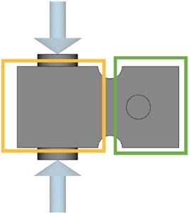
The initial idealized geometry, called rectangle (Fig. 1), developed under supervision of a dentist and mechanical engineers in accordance with intra oral pre requisites of the mouth regarding anatomic and physiologic patterns, was a solid cube, with a depth of 20 mm, 10 mm high and 10 mm wide, with two extensions (one at the top and one at the bottom) measuring 5 mm in diameter and 1.5 mm high, where the bite will be made (Fig. 1). The characteristics of the force applied by FEM in the pre-defined geometry was also decided by dentist and mechanical engineers characterizing the human bite. Only compression force was exerted on this first FEM simulation to look for failure in the geometry and material polymer used.
There is a relief with a radius of 1.5 mm at the top and bottom of the cube, separating its active portion (with the bite tip shown inside the orange rectangle in Fig. 1) from the holding part, after the relief (inside green rectangle in Fig. 1). On the opposite side of the bite tip, the piece will be fixed to a handlebar, used to wield the cube into be better position in the patient’s mouth during bite force tests. This part of the geometry was developed only by mechanical engineers.
Another six geometries developed by mechanical engineers were tested, all maintaining the geometry of the portion where the handle piece will be fixed. In Fig. 1 the region inside the green rectangle was kept the same way in all geometries, and in the region inside de orange rectangle (Fig. 1) the geometries were changed. They are: rectangle with 2 mm wall thickness, where a rectangular relief was created keeping the 2 mm wall; double “Y”: horizontal “double Y” structures with 1 mm walls; vertical “H”: with the intention of making the central region touch to avoid overloads, keeping 2 mm on the side walls and 1 mm on the H end; oval 1: (with the largest vertical diameter of 4.5 mm and horizontal of 3 mm); oval 2: with largest vertical diameter of 6 mm and horizontal of 3 mm) and asterisk: with 1 mm walls.
The region of force application is showed in the diameters highlighted in Fig. 2(c) and 3. In each geometry a minimum load of 40 N was applied to seek a minimum deformation capable of being captured by the CNT extensometer and a maximum load of 1 kN was applied to see if the deformation could be captured, and if there would be no failure in the structure. The loads applied were defined by the dentist and the CNT extensometer were developed by physicists.
The work was undertaken by applying direct deformations with values of 0.001 % = 10 N and 1.0 % = 1 kN. Therefore, 1.0 % deformation with 1 kN load is the condition to print the geometry for bench tests. These parameters were determined by the mechanical engineering team.
For finite element simulation, the SPACECLAIM (ANSYS, Canonsburg, PA, USA) and WORKBENCH (Oracle, Austin, TX, USA) programs were used. A static and compressive load was used for analysis and was applied by delimiting the areas of action with maximum deformation of 1 % on the surfaces at the interface with the strain gauge. To obtain the final contour conditions of the gnathodynamometer, two three-dimensional cubic solid elements (deformable and non-deformable region) were generated, a three-dimensional solid element of coupling of the two cubes was generated, a curvature mesh with 1.5 mm radius was generated, the tube was generated with 5 mm in diameter and 1.5 mm in height (force application site). Two curved meshes were united at each end of the coupling element, the meshes of the two hubs were united with the coupling element and the deformable part made the mesh union of the tubes. To generate another geometry of the gnathodynamometer, only the boundary conditions of the deformable part were changed. It was generated, hexahedral mesh with a size of 0.5 mm and tolerance of 0.025 mm for each of the three-dimensional solid elements. The choice of the programs and the FEM simulation were made by mechanical engineers with the supervision of load application on the load cell (direction and intensity) made by dentist.
The desired extensometer must have a minimal resolution of 1×10⁻⁶mm, the maximum deformation allowed by it should be 1 % of the total length, it must be rosette-shaped to enable capture of deformations in two directions, and its electrical resistance should be 350 Ohms. To enable adaptation at the bite tip, the maximum base dimensions of the extensometer must be 10 mm long and 7 mm wide at its base. The grills must be 2 mm long and 3 mm wide, and with their terminals these dimensions should be 4 mm long and 7 mm wide. Larger dimensions of the extensometer demand a larger bite tip and may compromise bite force data. An extensometer manufactured using nanotechnology, using carbon nano tubes (CNT) was used.
The arrangement formed by the CNT in the extensometer provides a network of conductive pathways for electrons, which is susceptible to disturbances induced by nano-scale mechanical deformations. When the film of nanotubes is pulled, the distance between the CNTs increases, decreasing the probability of tunneling the electrons between one tube and another. Consequently, the electrical resistance of the film increases. The opposite effect occurs when the film is compressed, which results in a decrease in its electrical resistance [41].
Two types of strain gauges were tested: a commercial model Omega (Spectris Company, Egham, Surrey, United Kingdom), based on a copper and nickel alloy and an experimental model based on a thin carbon nano tube film (CNT), developed at CT Nano, Universidade Federal de Minas Gerais (Belo Horizonte, MG, Brazil) [41]. These texts were made by physicists and electrical engineers.
CNT film is installed on a layer of insulating polymer deposited on the structure. This polymer, which can be acrylic, silicone, polyurethane, epoxy, polyamide based, among others, serves two purposes: to prevent the sensor from short circuiting when in close contact with metal structure and increase the adhesion of the film on the surface of the gnathodynamometer, to ensure a good load transfer. The electrical contacts of the sensor are made of silver paste and a second layer of polymer is deposited on the system to prevent unwanted effects of moisture influencing the measurement process. The CNT commercial 120 ohms extensometer were properly fixed. This part of the experiment was conducted by an electric engineer.
The on-board data recording and saving were developed using an Arduino nano prototyping platform to capture the electric signals of the extensometers, amplify and record it in a micro USB card. This was developed by an electrical engineer. The possibility of recording and storing data in the clouds was raised and for such the prototyping platform must be changed to a WeMos platform.
3. Results
3.1. Material definition
Based on the fundamental conditions of the gnathodynamometer listed in the foregoing text, the material proposed jointly by dentist and mechanical engineer for use is an autoclavable biocompatible resin, Dental Resin SG – Formlabs (Somerville, Ma, USA), because it has already been approved by ANVISA (National Agency of sanitary vigilance) and has well known mechanical properties, about which data is available for access at https://archivemedia.formlabs.com/upload/XL-DataSheet.pdf [42], printed in a 3D printer Formlabs Form 2 (Formlabs, Somerville, Ma, USA) with SLA technology.
3.2. FEM and geometry of the bite tip
Analysis of the deformations made by the FEM showed that the original geometry did not provide ideal conditions for bench tests. So, 6 other geometries were developed and tested, and showed the following results: the original geometry, and a rectangle with a 2 mm wall were shown to be extremely stiff. The geometries of double “Y”, vertical “H” showed to be fragile. The oval geometry 1 showed to be suboptimum, a little stiffer than the ideal. Oval 2 and asterisk geometries showed deformations close to expected.
Table 1Results of Deformation obtained with finite element simulation. MaL = maximum load; MiL = minimum load, VS = vertical strain; HS = horizontal strain; R = right side of the geometry, L = left side of the geometry
Model | MaL VS | MaL HS | MiL VS | MiL HS | ||||
R | L | R | L | R | L | R | L | |
Original/Rectangle | 0.04 % | 0.04 % | 0.01 % | 0.01 % | 0.00 % | 0.00 % | 0.00 % | 0.00 % |
Rectangle/2 mm wall | 0.03 % | 0.03 % | 0.01 % | 0.01 % | 0.00 % | 0.00 % | 0.00 % | 0.00 % |
Double “Y” | 0.02 % | 0.02 % | 1.70 % | 1.70 % | 1.30 % | 1.30 % | 0.00 % | 0.02 % |
Vertical “H” | 1.60 % | 1.60 % | 1.10 % | 1.10 % | 0.04 % | 0.04 % | 0.17 % | 0.17 % |
Oval 1 | 0.60 % | 0.45 % | 0.8 % | 0.56 % | 0.10 % | 0.01 % | 0.02 % | 0.01 % |
Oval 2 | 0.93 % | 0.76 % | 0.89 % | 0.58 % | 0.06 % | 0.05 % | 0.04 % | 0.02 % |
Asterisk | 0.80 % | 0.80 % | 0.20 % | 0.20 % | 0.02 % | 0.02 % | 0.05 % | 0.05 % |
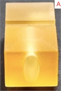
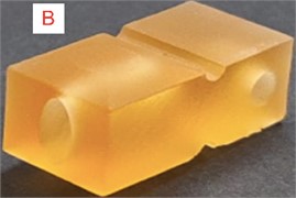
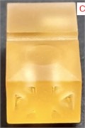
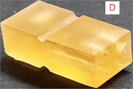
Therefore, the Oval 2 (Fig. 2(a, b)) and Asterisk (Fig. 2(c, d)) geometries were defined for follow-up with bench tests. The Oval 2 geometry presented results below 1 % of considerable deformation in the vertical and longitudinal directions of compression, provided relevant information about both directions of the force applied. The Asterisk geometry exhibited simulation with symmetrical results and deformations that differed a great deal between the axes described. 3D Printed geometries can be observed in Fig. 2.
Fig. 23D printed geometries chosen for bench tests: a) oval 2 geometry frontal view; b) oval 2 geometry lateral view; c) asterisk geometry frontal view; d) asterisk geometry lateral view
3.3. Extensometer
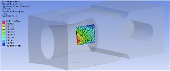
The choice of the best place to was based on the patterns of the load cell deformations. Quadrilaterals areas with the geometry of the extensometers were used to find the region in the load cell que have deformations que are better captured by the extensometers. The area with the geometry of the extensometer was tested by trial and error in different areas of the load cell geometry looking for the ideal place to fix the extensometer using FEM simulation. The best position to fix the extensometer in the Oval 2 and Asterix geometries was determined based on the deformations can be seen in Fig. 3 and Fig. 4 respectively. The electrical response of the two extensometers, obtained during test, showed that the CNT extensometer showed hysteresis, so it was discharged until improvements. The electrical response of the two extensometers, obtained during a compression test.
Fig. 3Results of FEM simulation of Oval 2 geometry showing the best location to fix the CNT extensometer
3.4. Codification, transmission and storage of data
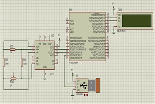
Electrical signal triggered by the deformed extensometer is sent to a converter module that sends the decoded data to a display, for reading. Using an Arduino Nano prototyping platform (Gravitec, Florianóplois, SC, Brazil) data can be storage in a micro SD 2G card; time provided by Real Time Clock RTC DS3231 (Maxim integrated, San Jose, CA, USA). Data can be sent to the clouds, for that it is necessary change the Arduino nano for a WeMos D1 1286, or 8266 platform. With the data on the clouds ThingSpeak(The MathWorks Inc, Natick, MA, USA) can be used to generate reports which send numerical data from the most widely differing devices, allowing this data to be visualized in the form of charts, over time, in any device connected to the clouds. If there is no internet signal, data will be stored on a micro SD card module for later uploading [43]. Diagram of the prototyping platform can be seen in Fig. 5.
Fig. 4Asterisk geometry. Results of FEM simulation of asterisk structure showing best location to fix CNT extensometer
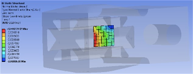
Fig. 5Diagram of extensometer data codification and transmission
3.5. Team work
The gaps of expertise of each professional area in the development of the load cell were clear to entire team. During the process of development expected appearing doubts of difficulties for a team member were solved by another member(s) of the team showing a time saving and an upgrade in the dispositive quality. Besides being an qualitative variable and, as such, subordinated to every team member personal impression, there was a consensus that the investigation described in this manuscript brought the same level of difficulties/problems that any other investigation would bring, but, due to the multidisciplinary team work problems were solved quicker, better and smarter than each team member was capable to solve alone (if he/she was able to solve it alone). Data provided by each member of the team in the development of the dispositive had an exponential effect on the entire development process.
3.6. Costs
The cost of the 3D printer was not included in this calculus, only material used. The printer wear was considered negligible and for such it was priced in 1 U$D. The polymer used costs 5 US$ in round numbers. The Arduino nano, wires, solders, 3d printing of a case for the arduino costs 21 U$D, the WeMos prototyping platform 25 US$. The cost of assembling the electrical part by a technician was estimated at 40 U$D. The manufacture costs of the dispositive are around 66 U$D with the Arduino nano and 70 U$D with the WeMos platform.
4. Discussion
The computational simulation performed through FEM was shown to be highly effective for reducing the costs and time spent on the creation, by lowering the printing from seven to two geometries of the gnathodynamometer for bench testing, in agreement with the literature [40].
The aim of this investigation appears to have been achieved since a gnathodynamometer can be quickly built, with proper low-cost CAD/CAM peripherals and, according to the preliminary bench results, with the necessary accuracy of results required for bite force data. Two 120 Ω extensometers found in the market were used and showed accuracy. The CNT extensometer showed hysteresis and needs more investigations to improve accuracy probably due to the distance between the strains gouge grids.
The Codification system was able to transmit data with precision and we developed a practical way to read and store data in the clouds. If access to internet is not possible there is a SD card in the device for later uploading, allowing easier transportation of the gnathodynamometer.
The dimensions of the bite tip are very similar to van Vuuren’s et al. [44] bite tip. The authors proved, in pre-clinical tests, that with this dimension, placing the bite tip between the teeth is more precise. Clinical investigations are necessary to study the ease and precision of positioning the gnathodynamometer in mouth and comfort for the tested individual.
Since there is no need to carry a computer or a scanner necessary, for instance for pressure films [37, 45, 46], because data will be store at the micro SD card or uploaded to the clouds, the hole set (clamp with bite tips, case with data codification and storage) is light and relatively small what make the transport of the gnathodynamometer easier, ideal for field data collection ideal for use in public health where there is no dental office available.
The costs to manufact the gnathodynamometer are about 35 times less than the final price for consumer of the dispositive used by Dizdarevic et al. [28] witch costs US$ 2,500.00. Of course, the final price for consumer of the dispositive developed here will rise due to profit and costs (manufacturer and seller), taxes but it is clear that will have a lower cost. The dispositive manufactured in by Kratos used by Manzon et al. [47]is bigger, heavier and costs approximately seven times more than the gnathodynamometer presented here and has a final price for consumers of 900 U$D in round numbers. To cost half the price of Kratos dispositive the final cost of the dispositive produced here would have to be raised almost 7 times, making it clear the price reduction compared with the ones in the market.
Teamwork was reported by each member as challenging in the beginning due to the unfamiliarity of a first-time participation in this team composition (mechanical an electric engineers, physicists, and dentist) but as the project progresses the team became more acquainted even with the terminology used by each profession and mainly with the way of thinking of them. It is a consensus that the teamwork eases the development and brings good ideas that contribute significantly to the final quality of the dispositive.
5. Conclusions
The interdisciplinary work generates prototypes with promising results in bench tests. The objective of construction of a low cost dispositive was achieved. The prototype developed showed promising results in FEM. Teamwork ease and save time in the development process of the dispositive.
References
-
A. Thomson, “Facial development,” International Journal of Orthodontia, Oral Surgery and Radiography, Vol. 11, No. 8, pp. 705–723, Aug. 1925, https://doi.org/10.1016/s0099-6963(25)90385-7
-
K. Maki, T. Nishioka, A. Morimoto, M. Naito, and M. Kimura, “A study on the measurement of occlusal force and masticatory efficiency in school age Japanese children,” International Journal of Paediatric Dentistry, Vol. 11, No. 4, pp. 281–285, Jul. 2008, https://doi.org/10.1046/j.1365-263x.2001.00298.x
-
D. E. Lieberman, G. E. Krovitz, F. W. Yates, M. Devlin, and M. St. Claire, “Effects of food processing on masticatory strain and craniofacial growth in a retrognathic face,” Journal of Human Evolution, Vol. 46, No. 6, pp. 655–677, Jun. 2004, https://doi.org/10.1016/j.jhevol.2004.03.005
-
W. R. Proffitt, H. W. Fields Jr, B. E. Larson, and D. M. Sarver, Contemporary Orthodontics. Elsevier, 2019.
-
K. D. Zink, D. E. Lieberman, and P. W. Lucas, “Food material properties and early hominin processing techniques,” Journal of Human Evolution, Vol. 77, pp. 155–166, Dec. 2014, https://doi.org/10.1016/j.jhevol.2014.06.012
-
M. L. Noback and K. Harvati, “The contribution of subsistence to global human cranial variation,” Journal of Human Evolution, Vol. 80, pp. 34–50, Mar. 2015, https://doi.org/10.1016/j.jhevol.2014.11.005
-
M. F. Laird, E. R. Vogel, and H. Pontzer, “Chewing efficiency and occlusal functional morphology in modern humans,” Journal of Human Evolution, Vol. 93, pp. 1–11, Apr. 2016, https://doi.org/10.1016/j.jhevol.2015.11.005
-
G. V. Black, “An investigation of the physical characters of the human teeth in relation to their diseases, and to practical dental operations together with the physical characters of filling materials,” The Dental Cosmos, Vol. 37, pp. 460–484, 1895.
-
M. A. Lamb, “Monthly bibliography of dental literature,” The Dental Cosmos, Vol. 37, pp. 466–468, 1895.
-
M. T. Marunick and R. H. Mathog, “Mastication in patients treated for head and neck cancer: A pilot study,” The Journal of Prosthetic Dentistry, Vol. 63, No. 5, pp. 566–573, May 1990, https://doi.org/10.1016/0022-3913(90)90078-q
-
P. Kemppainen, A. Waltimo, H. Palomäki, O. Salonen, M. Könönen, and M. Kaste, “Masticatory force and function in patients with hemispheric brain infarction and hemiplegia,” Journal of Dental Research, Vol. 78, No. 12, pp. 1810–1814, Nov. 2016, https://doi.org/10.1177/00220345990780120701
-
S. Yamashita, S. Sakai, J. P. Hatch, and J. D. Rugh, “Relationship between oral function and occlusal support in denture wearers,” Journal of Oral Rehabilitation, Vol. 27, No. 10, pp. 881–886, Oct. 2000, https://doi.org/10.1046/j.1365-2842.2000.00602.x
-
Y. Y. Shiau, C. C. Peng, S. C. Wen, L. D. Lin, J. S. Wang, and K. L. Lou, “The effects of masseter muscle pain on biting performance,” Journal of Oral Rehabilitation, Vol. 30, No. 10, pp. 978–984, Sep. 2003, https://doi.org/10.1046/j.1365-2842.2003.01159.x
-
W. Sun et al., “Ultrasound parameters of bone health and related physical measurement indicators for the community‐dwelling elderly in Japan,” Geriatrics and Gerontology International, Vol. 7, No. 2, pp. 154–159, Jun. 2007, https://doi.org/10.1111/j.1447-0594.2007.00390.x
-
T. K. Goto, T. Yamada, and K. Yoshiura, “Occlusal pressure, contact area, force and the correlation with the morphology of the jaw‐closing muscles in patients with skeletal mandibular asymmetry,” Journal of Oral Rehabilitation, Vol. 35, No. 8, pp. 594–603, Jul. 2008, https://doi.org/10.1111/j.1365-2842.2007.01837.x
-
K. S. Kim, Y. S. Byun, Y. J. Kim, and S. T. Kim, “Muscle weakness after repeated injection of botulinum toxin type a evaluated according to bite force measurement of human masseter muscle,” Dermatologic Surgery, Vol. 35, No. 12, pp. 1902–1907, Dec. 2009, https://doi.org/10.1111/j.1524-4725.2009.01319.x
-
G. S. Throckmorton, J. Rasmussen, and R. Caloss, “Calibration of T‐Scan sensors for recording bite forces in denture patients,” Journal of Oral Rehabilitation, Vol. 36, No. 9, pp. 636–643, Aug. 2009, https://doi.org/10.1111/j.1365-2842.2009.01978.x
-
S. Kiliaridis, “Masseter muscle thickness and maxillary dental arch width,” The European Journal of Orthodontics, Vol. 25, No. 3, pp. 259–263, Jun. 2003, https://doi.org/10.1093/ejo/25.3.259
-
G. Caroena, M. Mori, M. R. R. Gesualdi, E. A. Liberti, E. Ferrara, and M. Muramatsu, “Mastication effort study using photorefractive holographic interferometry technique,” Journal of Biomechanics, Vol. 43, No. 4, pp. 680–686, Mar. 2010, https://doi.org/10.1016/j.jbiomech.2009.10.025
-
G. Mountain, D. Wood, and J. Toumba, “Bite force measurement in children with primary dentition,” International Journal of Paediatric Dentistry, Vol. 21, No. 2, pp. 112–118, Aug. 2010, https://doi.org/10.1111/j.1365-263x.2010.01098.x
-
A. Shimada, S. Hara, and P. Svensson, “Effect of experimental jaw muscle pain on EMG activity and bite force distribution at different level of clenching,” Journal of Oral Rehabilitation, Vol. 40, No. 11, pp. 826–833, Aug. 2013, https://doi.org/10.1111/joor.12096
-
L. Lenguas, J. Alarcon, F. Venancio, M. Kassem, and C. Martin, “Surface electromyographic evaluation of jaw muscles in children with unilateral crossbite and lateral shift in the early mixed dentition. Sexual dimorphism,” Medicina Oral Patología Oral y Cirugia Bucal, Vol. 1, pp. e1096–e1102, Jan. 2012, https://doi.org/10.4317/medoral.17942
-
J. Kostrzewa-Janicka, E. Mierzwińska-Nastalska, G. Jarzębski, and P. Okoński, “Vertical jaw separation for vertical thickness of occlusal stabilization splint,” International journal of stomatology and occlusion medicine, Vol. 5, No. 1, pp. 20–27, Feb. 2012, https://doi.org/10.1007/s12548-012-0034-y
-
D. Flanagan, H. Ilies, B. O. ’Brien, A. Mcmanus, and B. Larrow, “Jaw bite force measurement device,” Journal of Oral Implantology, Vol. 38, No. 4, pp. 361–364, Aug. 2012, https://doi.org/10.1563/aaid-joi-d-10-00101
-
R. A. M. de Abreu, M. D. Pereira, F. Furtado, G. P. R. Prado, W. Mestriner, and L. M. Ferreira, “Masticatory efficiency and bite force in individuals with normal occlusion,” Archives of Oral Biology, Vol. 59, No. 10, pp. 1065–1074, Oct. 2014, https://doi.org/10.1016/j.archoralbio.2014.05.005
-
S. R. Crawford, A. M. Burden, J. M. Yates, P. Zioupos, and K. Winwood, “Can masticatory electromyography be normalised to submaximal bite force?,” Journal of Oral Rehabilitation, Vol. 42, No. 5, pp. 323–330, Jan. 2015, https://doi.org/10.1111/joor.12268
-
P. Mahoney et al., “Deciduous enamel 3D microwear texture analysis as an indicator of childhood diet in medieval Canterbury, England,” Journal of Archaeological Science, Vol. 66, pp. 128–136, Feb. 2016, https://doi.org/10.1016/j.jas.2016.01.007
-
D. Dizdarevic, T. Masic, and E. Muslic, “Lower jaw grip strength in healthy and sick population measured by special force transducer,” Acta Informatica Medica, Vol. 25, No. 4, p. 236, Jan. 2017, https://doi.org/10.5455/aim.2017.25.236-239
-
M. C. Goiato et al., “Does pain in the masseter and anterior temporal muscles influence maximal bite force?,” Archives of Oral Biology, Vol. 83, pp. 1–6, Nov. 2017, https://doi.org/10.1016/j.archoralbio.2017.06.029
-
A. Tarkowska, L. Katzer, and M. O. Ahlers, “Assessment of masticatory performance by means of a color-changeable chewing gum,” Journal of Prosthodontic Research, Vol. 61, No. 1, pp. 9–19, Jan. 2017, https://doi.org/10.1016/j.jpor.2016.04.004
-
Alireza Heydari, Yahya Baradaran Nakhjavani, Elnaz Askari Anaraki, Siavash Arvan, and Maryam Shafizadeh, “Bite force of children and adolescents: a systematic review and meta-analysis,” Journal of Clinical Pediatric Dentistry, Vol. 15, No. 1, p. 47, Jan. 2023, https://doi.org/10.22514/jocpd.2023.022
-
Y.T. Jou, “Dental deafferentation and brain damage: A review and a hypothesis,” The Kaohsiung Journal of Medical Sciences, Vol. 34, No. 4, pp. 231–237, Feb. 2018, https://doi.org/10.1016/j.kjms.2018.01.013
-
N. Almotairy, A. Kumar, M. Trulsson, and A. Grigoriadis, “Development of the jaw sensorimotor control and chewing – a systematic review,” Physiology and Behavior, Vol. 194, pp. 456–465, Oct. 2018, https://doi.org/10.1016/j.physbeh.2018.06.037
-
T. Takeshima, Y. Fujita, and K. Maki, “Factors associated with masticatory performance and swallowing threshold according to dental formula development,” Archives of Oral Biology, Vol. 99, pp. 51–57, Mar. 2019, https://doi.org/10.1016/j.archoralbio.2018.12.012
-
M. Iwasaki et al., “Capacitive-type pressure-mapping sensor for measuring bite force,” International Journal of Environmental Research and Public Health, Vol. 19, No. 3, p. 1273, Jan. 2022, https://doi.org/10.3390/ijerph19031273
-
M. Okada, K. Okada, and M. Kakehashi, “Common eating habit patterns are associated with a high maximum occlusal force and pre-eating cardiac vagal tone,” PeerJ, Vol. 11, p. e15091, Mar. 2023, https://doi.org/10.7717/peerj.15091
-
K. Oki et al., “The significance of posterior occlusal support of teeth and removable prostheses in oral functions and standing motion,” International Journal of Environmental Research and Public Health, Vol. 18, No. 13, p. 6776, Jun. 2021, https://doi.org/10.3390/ijerph18136776
-
V. F. Ferrario, C. Sforza, G. Zanotti, and G. M. Tartaglia, “Maximal bite forces in healthy young adults as predicted by surface electromyography,” Journal of Dentistry, Vol. 32, No. 6, pp. 451–457, Aug. 2004, https://doi.org/10.1016/j.jdent.2004.02.009
-
O. Santiago, M. V. L. Ferreira, and R. Huebner, “Do chewing simulators influence the test results of dental materials? Systematic review,” Jaw Functional Orthopedics and Craniofacial Growth, Vol. 3, No. 1, pp. 1–18, Jun. 2023, https://doi.org/10.21595/jfocg.2023.23270
-
G.-Y. He, D.-Y. Sun, S.-L. Zang, J. Chen, and Z.-H. Fang, “Evaluation of the elastic-plastic properties of TiN coating by nanoindentation technologies using FEM-reverse algorithm,” Surface and Coatings Technology, Vol. 409, p. 126855, Mar. 2021, https://doi.org/10.1016/j.surfcoat.2021.126855
-
T. H. R. Da Cunha et al., “High-yield synthesis of bundles of double – and triple-walled carbon nanotubes on aluminum flakes,” Carbon, Vol. 133, pp. 53–61, Jul. 2018, https://doi.org/10.1016/j.carbon.2018.03.014
-
“Formlabs”, https://archive-media.formlabs.com/upload/xl-datasheet.pdf
-
“ThingSpeak”, https://thingspeak.com/
-
L. Jansen van Vuuren, J. M. Broadbent, W. J. Duncan, and J. N. Waddell, “Maximum voluntary bite force, occlusal contact points and associated stresses on posterior teeth,” Journal of the Royal Society of New Zealand, Vol. 50, No. 1, pp. 132–143, Jan. 2020, https://doi.org/10.1080/03036758.2019.1691612
-
T. Kosaka et al., “A prediction model of masticatory performance change in 50 – to 70-year-old Japanese: The Suita study,” Journal of Dentistry, Vol. 104, p. 103535, Jan. 2021, https://doi.org/10.1016/j.jdent.2020.103535
-
M.-Y. Chang, G. Lee, Y.-J. Jung, and J.-S. Park, “Effect of neuromuscular electrical stimulation on masseter muscle thickness and maximal bite force among healthy community-dwelling persons aged 65 years and older: a randomized, double blind, placebo-controlled study,” International Journal of Environmental Research and Public Health, Vol. 17, No. 11, p. 3783, May 2020, https://doi.org/10.3390/ijerph17113783
-
L. Manzon, I. Vozza, and O. Poli, “Bite force in elderly with full natural dentition and different rehabilitation prosthesis,” International Journal of Environmental Research and Public Health, Vol. 18, No. 4, p. 1424, Feb. 2021, https://doi.org/10.3390/ijerph18041424
About this article
This study was funded by “National Council for Scientific and Technological Development – CNPq”. Brasilia, DF, Brazil. Grant number: 313145/2020-2.
The datasets generated during and/or analyzed during the current study are available from the corresponding author on reasonable request.
Orlando Santiago Júnior – conceptualization, investigation, methodology, writing - original draft preparation. Thiago H. R. da Cunha – data curation, formal analysis, methodology. Rodrigo G. Lacerda – data curation, methodology. Elizabeth Akemi Fujito – data curation, methodology. Marcus Vinicius Lucas Ferreira – methodology, writing-review and editing. Rudolf Huebner – conceptualization, project administration, resources, writing-review and editing.
The authors declare that they have no conflict of interest.
This article does not contain any studies with human participants performed by any of the authors
