Abstract
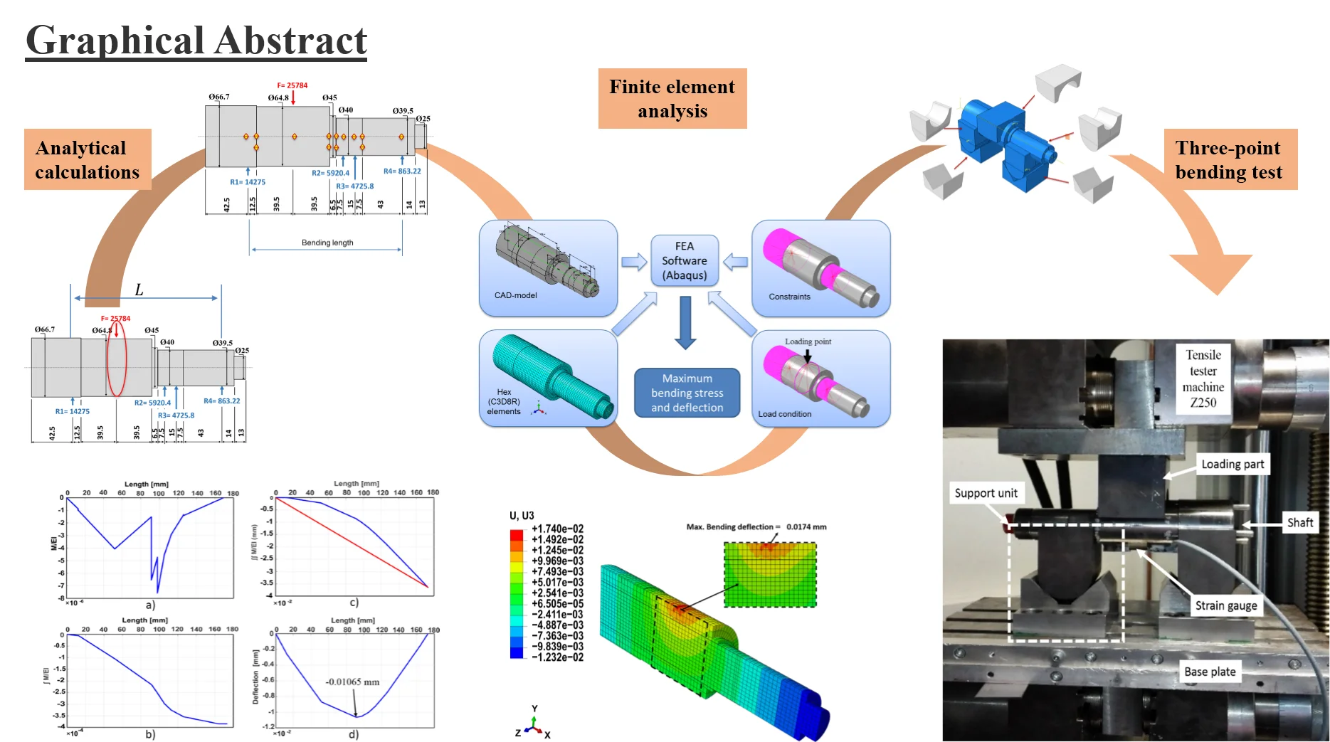
Increasing industrial demand for new products including advanced production technology leads to substantial natural resources consumption. Furthermore, huge environmental pollution and emerging environmental legislation motivate the machine tools industry as one of the major resource consumers on a global scale to develop methods for more sustainable use of the Earth's resources. Machine tools re-engineering concerning design and failure analysis is an approach by which outdated machines are upgraded and restored to like-new machines. To evaluate the mechanical failure of the used machine components and to ensure their reliable future performance, it is essential to make material, design, and surface investigations. In this paper, an experimental approach based on the principle of a three-point bending test is presented to evaluate the shaft elastic behavior under loading. Moreover, finite element analysis and numerical integration method are used to determine the maximum linear deflection and bending stress of the shaft. Subsequently, a comparison between the results is made. In conclusion, it was found that the measured bending deflection and stress were well close to the admissible design values. Therefore, the shaft can be used again in the second life cycle. However, based on previous surface tests conducted, the shaft surface needs re-carburizing and refining treatments to ensure the reliable performance of the surface.
Highlights
- Machine tools re-engineering concerning design and failure analysis is an approach by which outdated machines are upgraded and restored to like-new machines
- Mechanical failures analysis is necessary to evaluate the future material behavior of the old machine elements.
- Deflection of the shaft, as a case study, can be determined by numerical integration and FEA methods.
- Deflection and strain measurement can be performed by design an experimental approach based on three-point bending.
- Comparison of the results shows the elastic behavior of the old components.
- Old components can be used in multiple life cycles with or without some surface treatments.
1. Introduction
According to DIN 8586, rotary draw bending (RDB) is a forming process used for producing tubes with precise bending radii and wall thickness by the creation of a bending moment using RDB machines. Those machines are widely used in many industrial applications such as automotive industry, factories construction, and aerospace industry. Over the last decade, many new RDB machines were produced, and simultaneously, a tremendous amount of outdated bending machines exist. Therefore, some manufacturers use re-technique such as Re-engineering, Remanufacturing, Retrofit or Rebuild to recover and update an obsolete machine in order to manage their environmental responsibilities, reduce the production cost and decrease the resource consumption. RDB machine was analyzed to abstract the main components and assemblies, then, the shaft in Swing Arm and Bend Head assembly as a study case was investigated to evaluate its reliable performance.
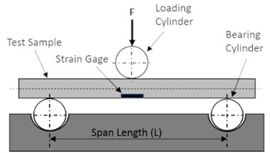
Shafts are used to transmit the rotary motion and power in the mechanical machines. The designer should ensure that the shaft geometry can cover the requirements of the material strength and shaft-supported components. A fluctuated loads condition or combined torsion and bending loads condition are the usual work conditions of shafts, which usually cause shaft deflection. Deflection analysis relies on the overall shaft geometry and the work condition. In general, shafts deflect linearly as a beam and angularly as a torsion bar [1]. To reuse the old shaft, it is necessary to take into consideration that the old shaft may not be suitable to reuse it again because of the effect of the first life cycle on the material strength. On the other hand, if the shaft shows poor performance under loading, shaft failure becomes predictable. Elastic properties and stiffness of materials under loading have high importance in the engineering design as well as it is significant to understand the effect of the material stiffness losing on the fracture of the designed components during its lifetime. Therefore, researchers and scientists developed many experimental techniques such as tensile test, three-point bending test, and four-point bending test, to determine the material mechanical characteristic [2]. A large number of investigations have been done to find appropriate techniques for assessing bending attributes of materials. Furthermore, global standardization organizations like the German Institute for Standardization (DIN), American Society for Testing and Materials (ASTM), and European Structural Integrity Society (ESIS) recommended some methods [3]. Three-point bending method is proposed in ASTM D790, ISO 178. It is a method specifies the mechanical behavior of the test sample subjected to a vertical load applied to its longitudinal axis at the midpoint between two supports [4-6]. The maximum bending moment along the length of the sample is at the loading point, and the transverse shear stress is constant between the supporting points and loading point. During the test, tensile stress is produced in the convex lower part of the test sample, compression stress is simultaneously created in the concave upper portion of the test sample, and shear stress is generated along the neutral axis [5]. In order to control the shear stress, the span length should be selected carefully [7]. The span length selection depends on the depth of a rectangular cross-section or the diameter of a circular cross-section of the test specimen. This testing method provides a reasonable estimation about the bending stress-strain response of the shaft material to a real load without destructing the shaft. Moreover, the bending stiffness of the shaft can be evaluated, and the effect of the first life cycle on the shaft material can be understood. A schematic of a three-point bending test setup is shown in Fig. 1(a).
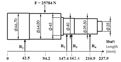
Fig. 1a) Sketch of the three-point bending test setup, b) shaft schematic shows load, reactions, and nominal dimensions
a)
b)
2. Methodology
Shaft deflection analysis and measurement consisted of the following steps. Firstly, maximum linear deflection and bending stress under a load of 25785 N were calculated by using numerical integration method and compared with the values acquired from finite element analysis (FEA) method by using Abaqus software. Secondly, a three-point bending test was designed and used to measure the shaft deflection and strain. The test approach was divided into two parts. The first part was regarding the test construction and fixture design including the calculation of the Hertzian stresses between the mating surfaces in the test assembly to design the test support parts and loading pin. Part two was related to measuring the strain and deflection on the shaft by using a strain gage and tensile tester machine (Z250) in order to compare the results with the previously calculated design values. At the end of this research and based on the reliable performance of the shaft in comparison to the design requirements, a decision was made to reuse the shaft in the second life cycle after applying some recommended surface treatments based on the results of the surface tests conducted previously [1].
3. Analytical calculations
A literature review to find a suitable method to estimate shaft deflection and slop indicates a wide variety of suitable scientific methods. Numerical integration, graphical integration, and FEA methods are the essential recommended methods in the case of a stepped shaft to calculate the maximum deflection [8]. In this analysis, the numerical integration method has been chosen. This method as a successive integration is an algebraically intensive concept but can be performed with the help of many software such as MATLAB and MATHCAD [9]. The proposed shaft is loaded with a 25785 N centered force, propped by three bearings, and a keyway is mounted at its end. Fig. 1(b) shows the shaft sketch.
The material that the shaft made of is C15Pb steel, which was specified by performing a test in (SPECTRO Analytical Instruments GmbH) company in Germany using Spectro technology. This material has a Yield strength of 385 MPa, the tensile strength of 500 MPa, Poisson’s ratio of 0.28, and Hardness of 143 HB. The deflection () and slope () along the shaft were determined according to Eq. (1)-(3) by using MATLAB software. Where is the applied moment, is the modulus of elasticity, and is the cross section’s area moment of inertia:
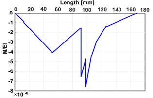
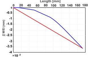
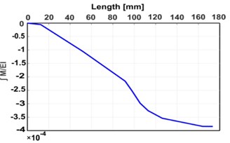
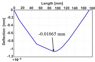
Moment function () is calculated at every point along the shaft that includes force, reaction, or change of the shaft diameter. Then, it is integrated to calculate the shaft slope function (), which is secondly integrated to determine the shaft deflection function () as plotted in Fig. 2(c). In this figure, the shaft deflection at a specific point is the vertical distance between the deflection curve and the base line that connected the support sites. Fig. 2 shows the results of the numerical integration method.
Fig. 2Analytical results: a) M/EI diagram, b) ∫M/EI diagram, c) ∬M/EI diagram, d) deflection diagram
a)
b)
c)
d)
To determine the maximum bending stress, bending moments along the bending length were calculated. The maximum moment of 728921 N.mm occurs at the loading point. At this point, the maximum bending stress was calculated according to Eq. (4) [10]. Here, , , and are the bending force, bending length, and shaft radius, respectively.
As a result of the analytical approach, the maximum bending deflection is 0.01065 mm, and the maximum bending stress is 33.903 MPa.
4. Finite element analysis approach
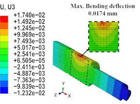
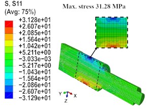
To understand how the stresses distribute along the shaft and to determine the maximum linear deflection value, the computational and powerful software Abaqus is employed. In the modeling process, the geometric shape, material properties, physical constraints, and the loading condition were defined. In the studied case, the shaft is supported by bearings located at its left and right ends, and a maximum load of 25785 N is applied to the shaft using a chain drive. This load is responsible for the rotation of the shaft and the generation of the torque that will be transferred to the bending arm through a keyway. Based on this work condition, the bending length of the shaft is between the left bearing and the shaft end where the keyway is mounted. The shaft geometry was divided into 29774 nods using Hex (C3D8R) elements. As a result, the maximum linear deflection of the shaft under a maximum loading condition is 0.0174 mm, and the maximum bending stress is 31.28 MPa. Both are induced at the shaft cross section where the force is applied, which are well below the permissible values. Fig. 3 shows the results of the FEA.
Fig. 3FEA results: a) bending deflection, b) bending stresses distribution
a)
b)
5. Experimental work
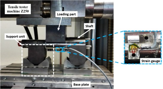
To measure the maximum linear deflection and maximum bending stress under a load of 25785 N, test methodology based on the principle of three-point bending test was performed. The experiment was carried out by certified operators and equipment as cited to the best experiences and appropriate guidelines. It was made in the laboratories of the Chair of Forming Technology /Mechanical Engineering Department at the University of Siegen in Germany. The test fixture was designed in a way that allows the shaft to bend elastically and gives no further stresses to the shaft. Furthermore, the test set-up with the designed fixture allows measuring the required data readily. The experimental apparatus construction was as follows. Two support parts with the contour of the shaft were designed, manufactured and mounted on the V blocks, which already existed. The support parts were designed to rotate freely to eliminate the frictional constraints. This assembly named a support unit where the shaft is sat. The support unit is mounted on a base plate. In this base plate, rectangular grooves for aligning and guiding the support unit are designed. Therefore, the distance between the two support units as well as the position of the loading unit can accurately and freely be selected and fixed. The loading unit, through which the load was applied to the shaft, was designed and screwed into 250 kN capacity load cell provided by Tensile tester machine Z250. The strain was measured using a strain gage glued to the bottom of the shaft under the loading point. The required data were observed during testing to evaluate and estimate the future behavior of the shaft. Fig. 4 shows the test set-up with the designed fixture.
Fig. 4The three-point bending test set-up
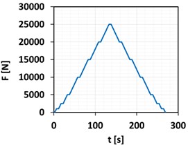
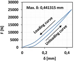
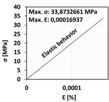
The force-time (-) curve and force-deflection (-) curve plotted by the tensile tester machine Z250 are shown in Fig. 5(a) and (b) respectively. Furthermore, the stress-strain (-) curve, which explains the elastic behavior of the shaft, is illustrated in Fig. 5(c). It can be noticed that the shaft bends elastically with a maximum bending strain of 0.00016937 during loading and go back to zero strain value after unloading.
The results of the analytical model, the FEA model, and the experimental approach were compared and reported in Table 1.
Fig. 5Measured values: a) force-time curve, b) force-deflection curve, c) stress-strain curve
a)
b)
c)
Table 1Comparison between the results obtained by the three approaches
Design specifications | Analytical model | FEA model | Experimental results |
Max. bending stress | 33.903 MPa | 31.28 MPa | 33. 8732661 MPa |
Max. bending deflection | 0.0106 mm | 0.0174 mm | 0.441315 mm |
6. Conclusions
The elastic behavior of the shaft was investigated under three-point bending test. Additionally, a finite element model was implemented using the FEA software Abaqus to predict the deflections and stresses in the shaft as a beam under loading. As a primary conclusion, the FEA model accurately reflects the experimental elastic behavior of the shaft. Moreover, the maximum bending stress and deflection values determined by the experiment is prognosticated with accurate results from the numerical Integration model. According to the experimental findings, it can be deduced that the value of the measured deflection of about 0.441315 mm was slightly higher than the calculated deflection. The difference reason is that the measured value represents the deflection of the whole test assembly and not only the deflection of the shaft. While the highest stress value of 33.8732661, which was determined by measuring the highest strain under maximum loading, was very close to the stress value calculated by using FE analysis method and numerical integration method. That means that the reliability of the shaft is still within the design limits. In conclusion, it is found that the used shaft still keeps the required material strength to be used in the second life cycle. However, there are apparent defects and wear on the shaft surface, which inspected previously [1], because of the influence of the first life cycle, so it is recommended to perform some surface treatments before the shaft is reused.
References
-
Engel B., Sara Salman Hassan Al Maeeni Failure analysis and fatigue life estimation of a shaft of a rotary draw bending machine. International Journal of Mechanical and Mechatronics Engineering, Vol. 11, Issue 11, 2017, p. 1763-1767.
-
Radovic M., Lara Curzio E., Riester L. Comparison of different experimental techniques for determination of elastic properties of solids. Materials Science and Engineering, Vol. 368, 2004, p. 56-70.
-
Petrescu Irina, Mohora Cristina, Ispas Constantin Determination of Young’s modulus for CFRP using the three-point bending test. Proceedings in manufacturing systems, Vol. 6, Issue 4, 2011, p. 254-260.
-
Zaharia S. M., Morariu C. O., Nedelcu A., Pop M. A. Experimental study of static and fatigue behavior of cfrp-balsa sandwiches under three-point flexural loading. BioResources, Vol. 12, Issue 2, 2017, p. 2673-2686.
-
Miljojković Jasmina, Bijelić Ivan, Vranić Nenad, Radovanović Nikola, Živković Milutin Determining elastic modulus of the material by measuring the deflection of the beam loaded in bending. Tehnički Vjesnik, Vol. 24, Issue 4, 2017, p. 1227-1234.
-
Nikhil R., Shivakumar S., Anupama K., Manjunath S., Raghuvir P. B., Mathew T. M. Experimental and numerical investigation of mode II failure behavior evaluation using three-point bend, end notched flexure test. MATEC Web Conferences, Vol. 144, 2018, p. 02009.
-
Morada G., Vadean A., Boukhili R. Failure mechanisms of a sandwich beam with an ATH/epoxy core under static and dynamic three-point bending. Composite Structures, Vol. 176, 2017, p. 281-293.
-
Collins Jack A. Mechanical Design of Machine Elements and Machines: a Failure Prevention Perspective. John Wiley and Sons, USA, 2003.
-
Odom E. M., Egelhoff C. J. teaching deflection of stepped shafts: Castigliano’s theorem, dummy loads, Heaviside step functions and numerical integration. 41st ASEE/IEEE Frontiers in Education Conference, 2011.
-
Callister W. D., Rethwisch D. G. Materials Science and Engineering: An Introduction. 9th Edition, John Wiley and Sons, 2013.
