Abstract
A multifunctional waist rehabilitation bed is designed for the traction therapy of human spine and gait rehabilitation training. The rehabilitation bed has four degrees of freedom, the rotation in the x, y, and z axis, and the movement in the z axis, which realizes traction treatment of lumbar spine rotation around coronal axis, vertical axis, sagittal axis and gait rehabilitation training. Considering the stability and safety during the rehabilitation process, the kinematic model of coronal-axis-rotation part, vertical-axis-rotation part and rehabilitation bed are established. Using MATLAB, the model and numerical simulation were carried out to obtain the curve of joint change when the waist rehabilitation bed was used for different functions, which verifies the effectiveness of the mechanism.
1. Introduction
With the increasingly serious global aging problem and the occurrence of various diseases, sports injuries and traffic accidents, the number of patients with lumbar or gait impairment has increased significantly [1]. In addition to early surgical treatment and necessary medical treatment, the study found, most patients early in the illness after non-surgical therapy can achieve an effective therapeutic effect [2]. Traction therapy and gait rehabilitation are common non-surgical therapies. Traction therapy applies force and reaction force to the spine to achieve separation of the articular surface, stretching the surrounding soft tissue and changing the angle or line between the bone structures [3, 4]. Gait rehabilitation training aims to achieve waist rehabilitation training by simulating the gait trajectory of the lower limbs of the human body [5].
Since the traction therapy is simple, widely applicable crowd characteristics, can be widely used in ordinary homes, nursing homes and rehabilitation hospitals, have great economic value. A large number of medical device companies have conducted research on traction beds. Lojer designed Manuthera 242 [6], the Mobility treatment can be carried out 3-dimensionally using the traction, flexion, lateral flexion and rotation features of the table, as well as gravity. Yin [7] designed a cable-pneumatic-muscle hybrid-driven waist rehabilitation robot for human waist and gait rehabilitation training, which enhanced the adaptability and safety to the patient.
A multifunctional waist rehabilitation bed designed in this paper combines traction therapy and gait rehabilitation training. In order to achieve the above functions, the rehabilitation bed has four degrees of freedom, the rotation in the x, y, and z directions, and the movement in the z direction, which realizes traction treatment of lumbar spine rotation around coronal axis, vertical axis, sagittal axis and gait rehabilitation training.
2. Mechanical structure design
2.1. Functional analysis
In this paper, a 4R waist rehabilitation bed is designed. The role of each function is shown in Table 1.
Table 1Waist rehabilitation bed function table
Function | Treatment |
Coronal-axis-rotation | a) When the nucleus pulposus protrudes backward (including left, right and central protrusions), it inclines downward. b) When the nucleus pulposus protrudes into the abdominal cavity, which is very rare in this patient, it inclines upward |
Vertical-axis-rotation | Scoliosis caused by left and right lumbar disc herniation |
Sagittal-axis-rotation | Scoliosis caused by left and right lumbar disc herniation |
Gait rehabilitation training | Promote central nervous system control of walking function, improve lower limb movement, sensory function, and correct abnormal gait of patients [7] |
2.2. Structural design
From Table 1, it is concluded that the waist rehabilitation bed requires four degrees of freedom. Fig. 1 shows a three-dimensional model of the bed. The designed mechanism includes coronal axis rotation part, sagittal axis rotation part, vertical-axis-rotation part and vertical axis movement part. The sagittal axis rotation parts are directly driven by the motor with reducer, which achieve the rotation around sagittal axis. The coronal-axis-rotation part and vertical axis rotation parts use the crank rocker mechanism, and the push rod motor is the active part, which has the characteristics of large thrust, stable movement and controllable speed. The forward and backward moving traction parts are composed of roller screw mechanism, which has the characteristics of smooth movement, high transmission efficiency, good synchronization and high precision.
Fig. 1Mechanical structure of waist rehabilitation bed

3. Kinematic analysis
3.1. Kinematics analysis of coronal-axis-rotation and vertical-axis-rotation
The coronal-axis-rotation and vertical-axis-rotation parts are connected by a push rod motor to move the bed body. Structure sketch of mechanism is shown as Fig. 2. l1 represents the distance between the bed’s rotating joint and the motor’s fixed position on the bed. l2 represents the distance between the bed’s rotating joint and the motor’s fixed position of on the axis. l3 represents the length of the push rod motor. φ1 represents the rotational angle of the bed. ω1 represents the rotational speed of the bed.a1 represents the rotational acceleration of the bed.
From the triangle cosine theorem, there are:
Eq. (1) derives the time, and organizes it to obtain ω1, as in:
Eq. (2) derives the time, and organizes it to obtain a1, as in:
Fig. 2Schematic diagram of mechanism
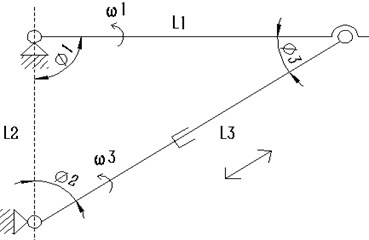
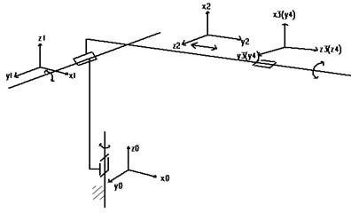
Fig. 3D-H link coordinate system
3.2. Kinematics analysis of rehabilitation bed
Robot’s kinematics analysis and solution are the basis of mechanism design, performance analysis and control, which include forward kinematics and inverse kinematics [8]. According to the 3D model of 4R rehabilitation bed in Fig. 1, each link coordinate system manipulator can be obtained in Fig. 3.
In Fig. 3, the bed’s D-H link parameters established by using the D-H method are shown in Table 2.
Table 2Rehabilitation bed’s D-H connecting rod parameter
Joint number | θ (°) | d(mm) | a (mm) | α (°) |
0-1 | θ1(0) | 0 | 0 | 90 |
1-2 | θ2(90) | 0 | 0 | 90 |
2-3 | θ3(0) | 0 | 0 | 90 |
3-4 | 0 | d4 | 0 | 90 |
According to [9], get each link coordinate system as follows:
A3=[c3-s3s3c3000000001001],A4=[1001000000001d401].
In the Eq. (4), si=sinθi, ci=cosθi.
Each connecting rod transformation matrix is multiplied, the rehabilitation bed’s transformation matrix A14 can be got, as in Eq. (5):
The inverse kinematics of the manipulator describes the mapping of end effector’s the Cartesian space to the joint space [14]. The inverse solution is to calculate the joint variables, such as θ1, θ2, θ3, d4, when the end position of the joint is known. The joint variables are solved as follows:
4. Numerical results and analysis
4.1. Simulation of oscillating slider mechanism
In this paper, the sagittal-axis-rotation and vertical axis movement parts are directly driven by the stepping motor, which can run smoothly. The coronal axis rotation and vertical axis rotation parts is driven by push rod motor, which form the oscillating slider mechanism. Installation parameters of two push rod motors are shown in Table 3.
Table 3Installation parameter table of push rod motor
Function | L1 / mm | L2 / mm | Motor parameter |
Coronal-axis-rotation | 200 | 200 | Push rod motor initial length 250 mm, stroke 100 mm |
Vertical-axis-rotation | 225 | 200 |
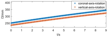
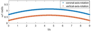
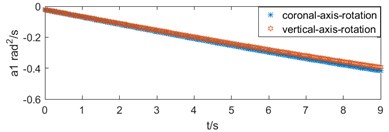
The length variation of the push rod motor is simulated by MATLAB in two motion modes, as shown in Fig. 4(a). The variation laws of bed’s the speed and acceleration are obtained, as shown in Fig. 4(b) and (c).
4.2. Simulation of gait rehabilitation
According to the requirement analysis of gait rehabilitation training, when normal people twist their waist, the trajectory of pelvic center approximates a circle, and the motion plane is horizontal. The trajectory equation is as follow:
Among them, x is displacement along sagittal axis, y is displacement along coronal axis, A is amplitude of motion, T is a period of motion.
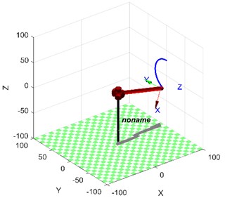
According to the Chapter 3, the kinematic model of the waist rehabilitation bed combined with the trajectory Eq. (7), the schematic diagram is obtained by using MATLAB simulation, as shown in Fig. 5.
Fig. 4Motion diagram: a) push rod motor’s length variation, b) bed’s speed variation, c) bed’s acceleration variation
a)
b)
c)
Fig. 5Gait trajectory simulation
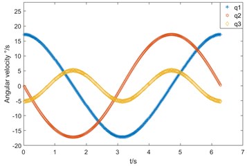
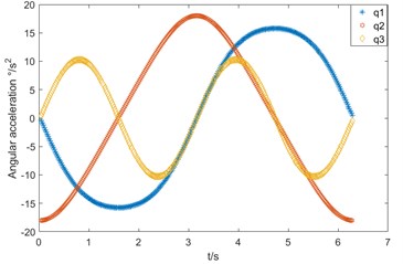
The joint variables of each joint in the waist rehabilitation bed are calculated by inverse kinematics with known motion trajectories. The velocity and acceleration of joint q1, q2 and q3 can be obtained by the first and second derivation of joint variable with time t. As shown in Fig. 7(a) and (b).
Fig. 6Joint motion diagram in gait rehabilitation: a) angular speed variation, b) angular acceleration variation
a)
b)
5. Conclusions
1) A multi-functional series waist rehabilitation bed was designed. It has four degrees of freedom, the rotation in the x, y, and z axis, and the movement in the z axis, which realizes traction treatment of lumbar spine rotation around coronal axis, vertical axis, sagittal axis and gait rehabilitation training.
2) Make the mechanism sketch and establish the kinematics model of coronal-axis-rotation and vertical-axis-rotation parts. The numerical simulation is carried out with this model. The velocity and acceleration curves are smooth without mutation. It is known from the dynamics knowledge that the waist rehabilitation bed’s movement is stable and safe.
3) For the waist rehabilitation bed, the reference coordinate system of each link is established by D-H, which gives the positional relationship between the links and the end of the bed and derives the kinematics of the rehabilitation bed.
4) According to the law of gait movement, the trajectory of gait rehabilitation function is designed. Combining the forward and inverse kinematics solutions, the velocity and acceleration curves of each joint are obtained by simulation, which are smooth continuous sinusoidal or cosine curves. It shows that the waist rehabilitation bed is effective.
References
-
Lee K. K., Teo E. C. Effects of laminectomy and facetectomy on the stability of the lumbar motion segment. Medical Engineering and Physics, Vol. 26, Issue 3, 2004, p. 183-192.
-
Cao Jinghui, et al. Control strategies for effective robot assisted gait rehabilitation: The state of art and future prospects. Medical Engineering and Physics, Vol. 36, Issue 12, 2014, p. 11555-1566.
-
Diego M. A., et al. Spinal cord patients benefit form massage therapy. International Journal of Neuroscience, Vol. 112, Issue 2, 2002, p. 133-142.
-
Swenson R., Haldeman S. Spinal manipulative therapy for low back pain. Journal of the American Academy of Orthopaedic Surgeons, Vol. 11, Issue 4, 2003, p. 228.
-
Esquenazi, et al. Robotic-assisted gait training and restoration. American Journal of Physical Medicine and Rehabilitation, Vol.91, Issue 91, 2012, p.217-31.
-
Manuthera 242 Mobilisation Table. Lojer, http://www.lojer.com/product/manuthera-242-mobilisation-table.
-
Yin Guangcai, et al. Mechanism design and kinematics analysis of a hybrid-driven waist rehabilitation robot. Journal of Mechanical Transmission, Vol. 4, 2016, p. 68-73.
-
Manocha Dinesh, Canny J. F. Efficient inverse kinematics for general 6R manipulators. IEEE Transactions on Robotics and Automation, Vol. 10, Issue 5, 1994, p. 648-657.
-
Rigelsford Jon Introduction to robotics: analysis, systems, application. Industrial Robot: An International Journal, Vol. 30 Issue 3, 2003, https://doi.org/10.1108/ir.2003.04930cae.002.

