Abstract
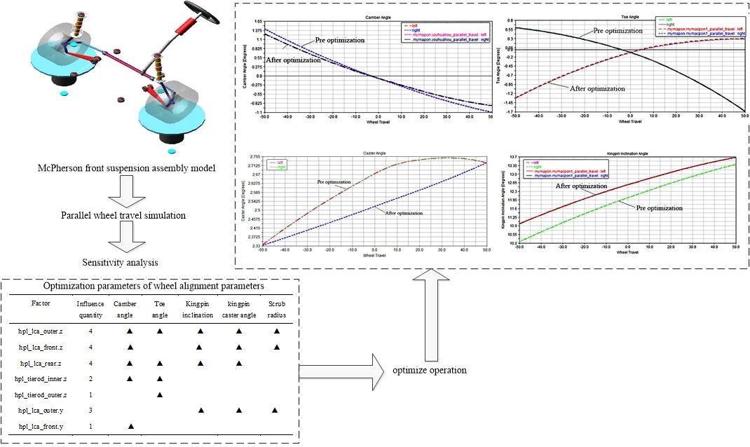
Suspension system is one of the key parts of vehicle, the performance of suspension system has great influence on vehicle handling stability and safety. In order to improve the performance of suspension system, the Macpherson suspension of a vehicle is taken as the research object, the suspension model is established by ADAMS/Car, and carried out parallel wheel travel simulation to analyze the key parameters variation of camber angle, toe angle, caster angle, kingpin inclination angle and scrub radius. Simulation results show that camber angle and scrub radius are beyond normal design range and require optimization. Wheel alignment parameters are determined by sensitivity analysis, and optimized by ADAMS/Insight. Then carried out simulation to analyze the performance of optimized suspension system. Results show that optimized suspension system satisfies the requirements of vehicle stability and safety.
Highlights
- This paper determined the optimized parameters of suspension system according to the parallel wheel travel simulation and sensitivity analysis
- The influence of scrub radius on suspension is considered during suspension optimization
- Wheel alignment parameters are determined by sensitivity analysis, and optimized by ADAMS/Insight
1. Introduction
Suspension system is an elastic device connecting frame and axle of vehicle, which transfer the force or torque between wheel and axle, cushion vibration and impact from ground to the vehicle body, and ensure vehicle normal running [1]. Wheel alignment parameters will change during the up-down movement of wheels, and too large variation range of wheel alignment parameters will adversely affect vehicle handling stability and safety.
The key parameters of suspension system include camber angle, toe angle, kingpin inclination angle, caster angle and scrub radius [2]. Liang et al. [3] determined hard point coordinates which have great influence on the front wheel alignment parameters by sensitivity analysis, and optimized the McPherson front suspension system by genetic algorithm, but it has not analyzed whether the optimized parameters of front suspension system meet the design requirements. Shi et al. [4] fitted wheel alignment parameters and tire radius by DOE Response Surface, optimized suspension alignment parameters by genetic algorithm toolbox, and results shows that this method enables suspension system has better performance. Trabelsi et al. [5] proposed a new design method to satisfy the static and dynamic design requirements of suspension system, and consideration of static and dynamic requirements globally in the preliminary design stage. Lu et al. [6] established the McPherson front suspension model of a vehicle by ADAMS/Car, and optimized the front suspension structure by Insight module, but hasn’t analyzed the variables which have great influence on wheel alignment parameters. Lee et al. [7] established a set of constraint equations for the joints constituting the suspension, and obtained the desired kinematic characteristics of the suspension by ADS, but that method only considered the camber angle and roll center height. Bhargav et al. [8] studied on the most widely used multi-objective evolutionary algorithms, such as NSGA-Ⅱ, SPEA2 and PESA-Ⅱ, and the advantages and disadvantages of the three algorithms are analyzed.
The McPherson suspension system simulation model of a micro electric vehicle is established by ADAMS/Car, the parallel wheel travel simulation analysis is carried out, the variation of camber angle, toe angle, caster angle, kingpin inclination angle and scrub radius are analyzed, and the wheel alignment parameters are determined by sensitivity analysis to optimized suspension system parameters.
2. Establishment of suspension model
The front wheel of micro electric vehicle researched in this paper adopts McPherson independent suspension, when the suspension is working, the shock absorber and the coil spring are assembled into one, which has good motion characteristics, strong handling stability and riding comfortability [9].
2.1. Determination of spatial topology
The spatial topology of McPherson suspension is shown in Fig. 1, where Fig.1, 1 is the left and right lower swing arm, 2 is the steering knuckle, 3 is the hub bearing, 4 is the wheel, 5 is the absorber,6 is the coil spring, 7 is the vehicle body, 8 is the steering tie rod, 9 is the steering gear rack, A is the upper fulcrum of the piston pole, B is the lower fulcrum of the piston pole, C is the center of steering knuckle, D is the wheel center, E is the joint of steering knuckle and lower swing arm, F is the joint of steering knuckle and steering tie rod, and G is the joint of steering tie rod end and hinged of steering gear rack.
Fig. 1Spatial topology of McPherson independent suspension
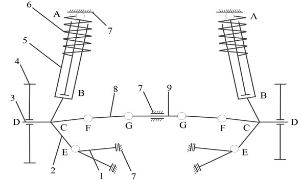
As shown in Fig. 1, the shock absorber consists of upper and lower piston pole, left and right lower swing arm 1 is connected with the center of steering knuckle 2, the lower fulcrum of the piston pole and vehicle body 7 through spherical pair. The upper fulcrum of the piston pole A is connected with vehicle body 7 through spherical pair, and the lower fulcrum of the piston pole is connected with steering knuckle 2 through spherical pair, which can only move and rotate along the axis. The outer end of steering tie rod 8 is connected with the steering knuckle arm through spherical pair, and the inner end of steering tie rod 8 is connected with the subframe through revolute pair [10].
The camber angle is the angle between the vertical axis of the wheel center plane and the vertical of road plane[11], the caster angle is the angle between the kingpin axis and the vertical of road plane in the Vehicle Longitudinal Plane [12], the kingpin inclination angle is the angle between the kingpin axis and the vertical the road plane in the lateral plane of the vehicle[13] and the scrub radius is distance between the kingpin axis and the center of the tire print on the ground [14].
The camber angle, caster angle, kingpin inclinational angle and scrub radius are shown in Fig. 2.
Fig. 2Camber angle, caster angle, kingpin inclinational angle and scrub radius
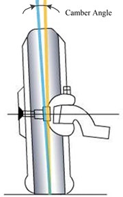
a) Camber angle
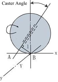
b) Caster angle
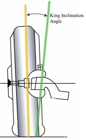
c) Kingpin inclinational angle
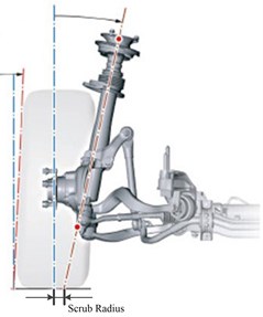
d) Scrub radius
Major constraint relations of McPherson suspension components are shown in Table 1.
Table 1Major constraint relations of McPherson suspension components
Connector | Connector | Kinematic constraint |
Upper end of piston pole | Vehicle body | Spherical pair |
Steering knuckle | Lower end of piston pole | Cylindrical pair |
Outer end of steering tie rod | Steering knuckle | Spherical pair |
Inner end of steering tie rod | Steering knuckle | Spherical pair |
Outer end of lower swing arm | Vehicle body | Revolute pair |
Inner end of lower swing arm | Steering knuckle | Spherical pair |
2.2. Parameters setting
The McPherson suspension model is obtained by modifying the hard point coordinates based on the original model of Adams/Car. According to the parameters of micro electric vehicle, the static load radius is set to 208.6 mm, the tire stiffness is set to 200 N/rad, the sprung mass is set to 342 Kg, the hight of mass center is set to 320 mm, the wheelbase is set to 1765 mm, and front wheel drive. The McPherson suspension model is assembled with MDI_SDI_TESTRIG test bench, the McPherson front suspension assembly model is shown in Fig. 3, and then carried out parallel wheel travel simulation.
Fig. 3McPherson front suspension assembly model
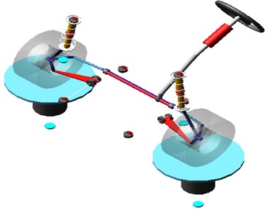
2.3. Analysis of simulation results
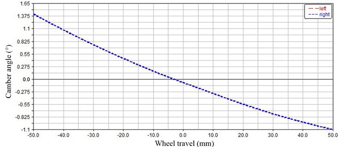
In order to facilitate simulation analysis, we adopt an idealized hypothesis method in this paper. The variation of camber angle is shown in Fig. 4. As shown in Fig. 4, the value of camber angle ranges from –1.09° to 1.42° during whole process, and the camber angle is –0.14° at static balance. The fluctuation of camber angle is small during the upward process, and the variation range of camber angle during the upward process is –1.09° to –0.14°. The fluctuation of camber angle is larger during the downward process, and the maximum value is 1.42°. According to the requirement of camber angle value –2° to 0.5°during the upward process [15], it can be known that the suspension of micro electric vehicle does not meet the design requirement and needs to be optimized.
Fig. 4Variation of camber angle
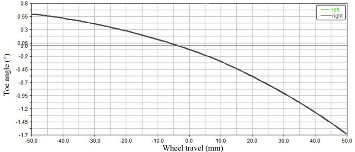
The variation of toe angle is shown in Fig. 5. As shown in Fig. 5, the value of toe angle ranges from 0.599° to 1.684° during whole process, and the toe angle is –0.075° at static balance. The fluctuation of toe angle is small during the upward process, and the maximum of toe angle is –1.684°. The fluctuation of toe angle is larger during the downward process, and the maximum of toe angle is 0.599°. According to the design requirements of vehicle suspension, the toe angle should between 0 to 0.5°during the upward process [16], so the toe angle does not meet the design requirements and needs to be optimized.
Fig. 5Variation of toe angle
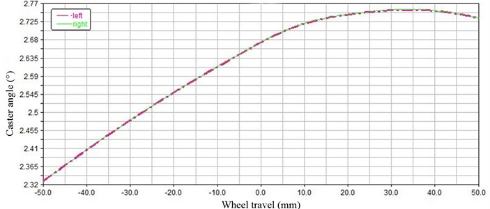
The variation of caster angle is shown in Fig. 6. As shown in Fig. 6, the value of caster angle ranges from 2.328° to 2.755° during whole process, the change amount is 0.428°, and the caster angle is 2.673° at static balance. The fluctuation of caster angle is small during the upward process, and the maximum of caster angle is 2.755°. The fluctuation of caster angle is larger during the downward process, and the minimum of caster angle is 2.328°. According to the design requirements of vehicle suspension, the caster angle satisfies the design requirements.
Fig. 6Variation of caster angle
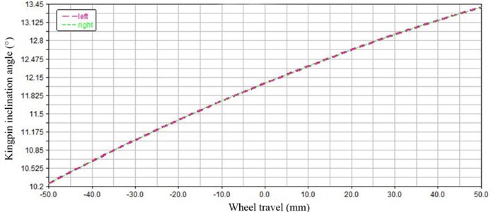
The variation of kingpin inclination angle is shown in Fig. 7. As shown in Fig. 7, the value of kingpin inclination angle ranges from 10.257° to 13.394° during whole process, and the kingpin inclination angle is 12.04° at static balance. The fluctuation of kingpin inclination angle is larger during the upward process, and the maximum of kingpin inclination angle is 13.394°. The fluctuation of caster angle is small during the downward process, and the maximum of kingpin inclination angle is 10.257°. According to the design requirements of vehicle suspension, the kingpin inclination angle should between 5° to 15° [17], so the kingpin inclination angle satisfies the design requirements.
Fig. 7Variation of kingpin inclination angle
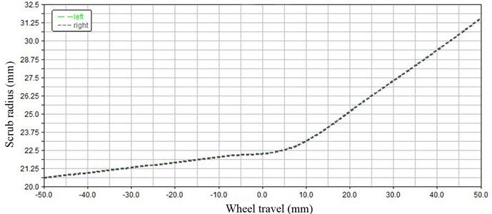
The variation of scrub radius is shown in Fig. 8. As shown in Fig. 8, the value of scrub radius ranges from 20.64 mm to 31.559 mm during whole process, and the scrub radius is –22.29 mm at static balance. The fluctuation of scrub radius is larger during the upward process, and the maximum of scrub radius is 31.559 mm. The fluctuation of scrub radius is small during the downward process, and the maximum of scrub radius is 20.64 mm. According to the design requirements of vehicle suspension, the scrub radius should between –10 mm to 30 mm during the upward process [18], so the scrub radius does not meet the design requirements and needs to be optimized.
Fig. 8Variation of scrub radius
3. Sensitivity analysis
After the parallel wheel travel simulation, the optimization variables of wheel alignment parameters are determined by sensitivity analysis. Four optimization objectives are created at the Adams/Insight, which are camber angle, caster angle, kingpin inclination angle and scrub radius. The variation range of each value is set at –50 mm to 50 mm [17]. After sensitivity analysis, the factors have greatest impact on optimization objectives are determined. Considering that the main optimization parameters are camber angle and scrub radius, the optimization parameters of wheel alignment parameters are finally determined, as shown in Table 2.
Table 2Optimization parameters of wheel alignment parameters
Factor | Influence quantity | Camber angle | Kingpin inclination angle | Caster angle | Scrub radius |
hpl_lca_outer.z | 4 | ▲ | ▲ | ▲ | ▲ |
hpl_lca_front.z | 4 | ▲ | ▲ | ▲ | ▲ |
hpl_lca_rear.z | 4 | ▲ | ▲ | ▲ | |
hpl_tierod_inner.z | 2 | ▲ | |||
hpl_tierod_outer.z | 1 | ||||
hpl_lca_outer.y | 3 | ▲ | ▲ | ▲ | |
hpl_lca_front.y | 1 | ▲ |
Combined with Table 2, the hard point coordinates of wheel alignment parameters affecting vehicle handling and stability are final determined as the Y and Z coordinates of hpl_lca_front, the Z coordinates of hpl_lca_rear, the Y and Z coordinates of hpl_lca_outer, the Z coordinates of hpl_tierod_inner and the Y and Z coordinates of hpl_tierod_outer.
4. Comparative analysis of simulation
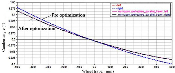
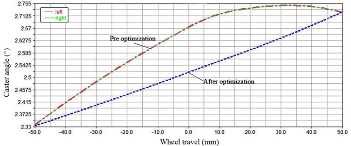
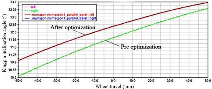
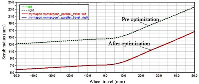
After determined the optimization objectives, then carried out optimization and obtained hard point coordinates data after optimization. The optimization model is obtained by changed the original suspension hard point coordinates based on optimized hard point coordinates data. Parallel wheel travel simulation is carried out after above amendments, the wheel alignment parameters curves before and after optimization are shown in Fig. 9 to Fig. 12.
4.1. Comparative analysis of camber angle before and after optimization
The curves of camber angle before and after optimization is shown in Fig. 9. As shown in Fig. 9, the value of optimized camber angle ranges from –1.237° to 0.911° during whole process, and the camber angle is 0.075° at static balance. During the upward process, the value of camber angle ranges from 0.075° to 0.911°, and the maximum of camber angle is 0.911°. During the downward process, the maximum of camber angle is –1.237°, and the change amount is 2.418°. It can be known that the optimized camber angle satisfies the design requirements.
Fig. 9Camber angle before and after optimization
4.2. Comparative analysis of caster angle before and after optimization
The curves of caster angle before and after optimization is shown in Fig. 10. As shown in Fig. 10, the value of optimized caster angle ranges from 2.336° to 2.749° during whole process, the change amount is 0.413°, and the caster angle is 2.54° at static balance. According to the design requirements of vehicle suspension, the caster angle changes from 1° to 7° of front-engine and front-wheel drive layout, and generally does not exceed 3° of the vehicles [19], It can be known that the optimized caster angle satisfy the design requirements.
Fig. 10Caster angle before and after optimization
4.3. Comparative analysis of kingpin inclination angle before and after optimization
The curves of kingpin inclination angle before and after optimization is shown in Fig. 11. As shown in Fig. 11, the value of optimized kingpin inclination angle ranges from 10.398° to 13.681° during whole process, and the kingpin inclination angle is 12.7° at static balance.
After optimization the change range of kingpin inclination angle is further reduced, the maximum of kingpin inclination angle is 13.681° during the upward process and 10.983° during the downward process, and the change amount is 2.137°. According to the design requirements of the vehicle suspension, the optimized kingpin inclination angle is more satisfy the design requirements.
Fig. 11Kingpin inclination angle before and after optimization
4.4. Comparative analysis of scrub radius before and after optimization
The curves of scrub radius before and after optimization is shown in Fig. 12. As shown in Fig. 12, the value of optimized scrub radius ranges from 5.82 mm to 16.66 mm during whole process, the change amount is 10.85 mm, and the scrub radius is 7.19 mm at static balance. The maximum of scrub radius is 16.665 mm during the upward process and 5.817 mm during the downward process. According to the design requirements of vehicle suspension, the scrub radius should within –10 mm to 30 mm. It can be known that optimized scrub radius satisfies the design requirements.
Fig. 12Scrub radius before and after optimization
The wheel alignment parameters before and after optimization are shown in Table 3.
Table 3Wheel alignment parameters before and after optimization
Optimization goal | Variation range before optimization | Change amount | Variation range after optimization | Change amount |
Camber angle | [–1.09°, 1.42°] | 2.51° | [–1.237°, 0.911°] | 2.148° |
Caster angle | [2.328°, 2.755°] | 0.427° | [2.336°, 2.749°] | 0.413° |
Kingpin inclination angle | [10.257°, 13.394°] | 2.698° | [10.983°, 13.681°] | 3.137° |
Scrub radius | [20.644 mm, 31.559 mm] | 10.915 mm | [5.817 mm, 16.665 mm] | 10.848 mm |
5. Conclusions
The McPherson suspension model of a micro electric vehicle is established by Adams/Car, and parallel wheel travel simulation is carried out to analyze wheel alignment parameters, such as camber angle, toe angle, caster angle, kingpin inclination angle and scrub radius, which provides a theoretical basis for further research work.
The optimization target of the McPherson suspension wheel alignment parameters is determined through sensitivity analysis, and optimized by ADAMS/Insight. Parallel wheel travel simulation is carried out again to analyze wheel alignment parameters before and after optimization, the simulation results show that optimized suspension parameters are more satisfy with the design requirements and can improve the vehicle handling stability.
References
-
Emre S., Pınar B. Optimization of suspension system and sensitivity analysis for improvement of stability in a midsize heavy vehicle. Engineering Science and Technology, an International Journal, Vol. 20, Issue 3, 2017, p. 997-1012.
-
Koensgen E., Berger S., Bouet C., et al. Robust design strategy applied to a vehicle suspension system with high camber angle tyres. International Journal of Vehicle Design, Vol. 62, 2014, p. 42-71.
-
Liang Y. Q., Bi F. G., Shi C. F. Parametric optimization research for MacPherson suspension based on genetic algorithm. Journal of Machine Design, Vol. 34, 2017, p. 15-19.
-
Shi J., Sun Y., Li W. M. Analysis and optimization of mini electric car front suspension. Machinery Design and Manufacture, 2015, p. 65-68.
-
Trabelsi H., Yvars P. A., Louati J., et al. Application of set-based-approach for the global sizing of an active MacPherson suspension system. International Conference Design and Modeling of Mechanical Systems, 2017, p. 1081-1091.
-
Lu J. M., Lu T. L., Shen Y. Optimization of the structure of MacPherson suspension based on vehicle handling stability. Drive System Technique, Vol. 32, 2018, p. 3-7+26.
-
Lee C. R., Kim H. J. Design optimization for kinematic characteristics of automotive suspension considering constraints. Journal of the Korea Academia-Industrial, Vol. 18, Issue 3, 2017, p. 306-311.
-
Bhargav G., Vimal S., Vivek P. Multi-objective optimization of vehicle passive suspension system using NSG-Ⅱ, SPEA2 and PESA-Ⅱ. Procedia Technology, Vol. 23, 2016, p. 361-368.
-
Reddy K. V., Kodati M., Chatra K., et al. A comprehensive kinematic analysis of the double wishbone and MacPherson strut suspension systems. Mechanism and Machine Theory, 2016, p. 441-470.
-
Kavitha C., Abinav Shankar S., Ashok B., Denis Ashok S., Hafiz Ahmed, Muhammad Usman Kaisan Adaptive suspension strategy for a double wishbone suspension through camber and toe optimization. Engineering Science and Technology, Vol. 21, Issue 1, 2018, p. 149-158.
-
Lajqi S., Pehan S., Lajqi N., et al. Design of independent suspension mechanism for a terrain vehicle with four wheels drive and four wheels steering. Annals of the Faculty of Engineering Hunedoara, Vol. 11, Issue 1, 2013, p. 101-108.
-
De Filippi P., Tanelli M., et al. Design of steering angle observers for the active control of two-wheeled vehicles. IEEE International Conference on Control Applications, 2010, p. 155-160.
-
Munoz B., Ramirez M., Díaz V. Development of a new methodology for vehicle steering system inspection. Proceedings of the Institution of Mechanical Engineers, Part D: Journal of Automobile Engineering, Vol. 220, Issue 11, 2006, p. 1515-1526.
-
Theander A. Design of a Suspension for a Formula Student Race Car. Master Thesis, Royal Institute of Technology, 2004.
-
Liang Y. Q. The Suspension Multi-body Dynamic Analysis and Steering Transient Response Research of Vehicle Based on ADAMS. Tianjin University, 2016.
-
Wang R. P., Luan Z. Y., Mao C. X., et al. Macpherson front suspension optimization based on ADAMS/Car. Journal of Guangxi University, 2014, p. 294-299.
-
Tang R. Q., Guo L. Influence of kingpin inclination angle and offset on automobile suspension and steering system performance. Mechanical Engineering and Automation, 2017, p. 35-37.
-
Zhang G. H., Lin L. H., Xu H. G. Front suspension modeling and simulation optimization based on virtual prototype. Journal of Chinese Agricultural Mechanization, Vol. 36, 2015, p. 200-202+214.
-
Huang W. T., Gao Q. Optimization design of MacPherson rear suspension. Machinery Design and Manufacture, 2016, p. 167-170.
About this article
The authors would like to thank anonymous reviewers for their helpful comments and suggestions to improve the manuscript. This research was supported by the National Natural Science Foundation of China (Grant No. 51565011), and the Natural Science Foundation for Distinguished Young Scholars of Jiangxi province (Grant No. 20171BCB23059), and the Key Research Program of Jiangxi Province (Grant No. 20171BBE50039), and the Natural Science Foundation of Jiangxi Province (Grant No. 20171BAB216027).
Qiping Chen is the sponsor and instructor of this paper. Sheng Kang assisted in the writing of this paper. Xiangqin Li is the model builder and simulation analyst of this paper. Mingming Wu is the translator of this paper. Jiacheng Wei is the assistant of model building in this paper. Yu Liu is the proofreader of this article.

