Abstract
Variable pitch control is an effective way to ensure the constant power operation of the wind turbines over rated wind speed. The pitch actuator acts frequently with larger amplitude and the increasing mechanical fatigue load of parts of wind turbines affects the output quality of generator and damages the service life of wind turbines. The existing switching control methods only switch at a certain threshold, which can result in switch oscillation. In order to deal with these problems, a multi-mode soft switching variable pitch control strategy was put forward based on Takagi-Sugeno (T-S) fuzzy weighted to accomplish soft switch, which combined intelligent control with classical control. The T-S fuzzy inference was carried out according to the error and its change rate, which was used to smooth the modal outputs of fuzzy control, radial basis function neuron network proportion integration differentiation (RBFNN PID) control and proportion integration (PI) control. This method takes the advantages of the three controllers into consideration. A multi-mode soft switch control model for variable pitch of permanent magnet direct drive wind turbines was built in the paper. The simulation results show that this method has the advantages of three control modes, switch oscillation is overcome. The integrated control performance is superior to the others, which can not only stabilize the output power of wind turbines but also reduce the fatigue load.
Highlights
- A novel pitch control strategy is put forward
- Multi-mode control is used in variable pitch of wind turbines
- T-S fuzzy weighed is used to overcome switch oscillation
1. Introduction
Recently, with the decrease of fossil fuels and the increase of human awareness of environmental protection, the attracting attention is giving to renewable resources, especially wind energy [1-3]. Wind turbines are mostly used in wind energy conversion systems, which capture the energy of wind and then convert it to useful mechanical or electrical energy.
The intermittency and randomness of wind made it difficult to control the wind turbines. The more safety and reliable variable pitch control scheme is needed for active variable pitch wind turbines [4]. Variable pitch control system is one of the important parts for variable-speed constant-frequency wind turbines, which is usually used in medium or large wind power systems [5]. The objective of control scheme is to keep the constant power operation and decrease the fatigue load of parts of wind turbines [6]. Aerodynamic torque and extra power absorption of wind turbine can be limited by variable pitch control [7]. The classical PID control is widely used and easy to be realized, it has not a good effect on torque and pitch angle control [8-10]. By using gain scheduling to deal with nonlinear aerodynamic characteristics, the control performance is improved but not satisfactory. Some advanced strategies have been proposed, such as fuzzy control [11], LQG control [12], H∞ control [13] and sliding-mode control [14, 15], these methods are designed for multi-objective optimization but very complex to be completed. When the state trajectory reaches the sliding mode, the sliding mode control has high frequency oscillation problems. (Ren, et al) proposed a novel pitch control strategy based on bee colony algorithm which shows the good robustness but the bad stability of wind turbines [16], when the wind power system appears random disturbance, the control system is prone to instability. Fuzzy pitch controller has excellent rapidity and robustness which is relatively mature and hardware implementation. RBF neural network pitch control has strong adaptability, good robustness and dynamic performance. Multi-mode control has better anti-interference performance than single mode control.
In this paper, a new variable pitch control scheme based on T-S fuzzy inference is proposed to ensure the constant operation of wind turbines above rated wind, which combined the intelligent control with classical control. By using the rapidity of fuzzy control to decrease error and suppress the rapid change of error when the error is larger; taking advantage of RBFNN PID control to adjust timely in medium error; switching to PI control to enhance its static precision. According to the error and its change rate, which is the difference generator’s speed and its rated rotor speed, the switch between three controllers makes use of the T-S fuzzy inference and uses the weighted average method to output the coefficients, the synthetic output adopts the weighted sum method.
2. Wind turbines model
2.1. The combined wind model
The wind has a strong randomness and mutability in the flow process, a model is required that can properly simulate the spatial effect of wind behavior, including gusting, rapid (ramp) changes, and background noise [17, 18].
The wind model chosen for this simulation is a four-component model and is defined by:
where, vb is the base wind velocity, m/s; vg is the gust wind component, m/s; vr is the ramp wind component, m/s; vn is the noise wind component, m/s; vw is the combined wind m/s.
These four components provide a reasonable flexibility for the study of one or a group of wind turbines.
The base wind velocity component can be described as:
where, l and s are the proportion and shape parameters of Weibull distribution; Γ(⋅) is Gamma function.
The gust wind velocity component is given by:
where, t1g is the gust starting time; tg is the gust period time; vgmax is the gust peak; t is time.
The ramp wind velocity component is stated as:
where, t1r is the ramp start time; t2r is the ramp stop time; tr is the ramp period time; vrmax is the ramp peak.
The final wind velocity component is the random noise component, it can defined by:
where, ωi=(i-1/2)Δω0;Sr(ωi)=2μF2|ωi|/π2[1+(Fωi/πvb)2]4/3;φi is a random variable with uniform probability density on the interval 0 to 2π; μ is the mean speed of wind at reference height; F is the turbulence scale; Δω0 is an accuracy frequency.
The wind model was installed in a program by adding a special function module to provide vw given the parameters of the four wind components.
2.2. PMSG Wind turbines model
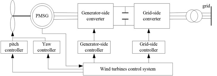
The structure of direct-drive PMSG (permanent magnet synchronous generator) wind turbines is shown in Fig. 1. The wind turbines studied in this paper is a class of 2 MW horizontal axis and variable speed variable pitch wind turbines. The major components of this wind turbines model are the aerodynamic system, PMSG, generator-side converter, grid-side converter, generator-side controller, grid-side controller, pitch controller, yaw controller and wind turbine control system. Maximum wind tracking is carried out under the rated wind speed and the rotor speed of generator is controlled by the electromagnetic torque of the machine controller. The goal of pitch control above rated wind speed is to control pitch angle and regulate rotor speed to the rated power. To account for variations in wind, the pitch control response must be fast.
Fig. 1The structure of direct-drive PMSG wind turbines
2.3. Aerodynamic model
According to Batz’s law, all power cannot be absolutely captured by wind turbines while converting wind energy into mechanical energy. Yang et al. established the aerodynamic power absorbed by wind turbines [19], which is shown in:
where, Pm is the aerodynamic power; ρ is the air density; R is the pitch radius; v is the wind speed; CP is the power coefficient, which depend on pitch angle β and tip speed ratio λ. The tip speed ratio is described as follows:
where, ωf is the rotor speed.
CP is expressed as:
where, λ1=1λ+0.08β-0.0035β3+1.
The aerodynamic torque is also given by:
2.4. Pitch actuator model
The pitch angle control is usually applied to limit the output power of wind turbine in the medium or large wind turbines. The hydraulic device and motor drive are two types of actuators which are used to turn the blades of the wind turbine around their longitudinal axis. It can be simplified by one order inertial link. In the closed loop, an integrator, a pitch angle limiter, and a pitch angle rate limiter are included.
The dynamic behavior of the pitch servo is expressed as:
where, τb is a constant time, β is the pitch angle, βref is reference pitch angle.
The response of pitch control depends on the time constant of the pitch actuator, which is normally in a small range. Typically, the pitch angle ranges from 0 to 25 degrees and varies at the maximum rate of ±10°/s. The transient performance of the pitch control depends on the pitch rate. Hence, the variable range and the rate of change in the pitch angle have enormous influence on the performance of power output, these limits are not reached during the normal operation of wind turbine in order to decrease the risk of the fatigue damage.
3. Pitch control strategy
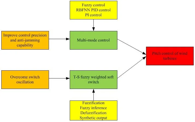
Pitch control is an effective method to ensure constant power output of wind turbines, which is used to decrease the overload of wind turbines over rated wind speed and makes the most efficient operation of wind turbines. The mechanical fatigue can be decreased, and extra power absorption can be limited. In many control schemes, the rotational speed of blade is regulated by measuring wind speed in real time, it is not accurate due to the wind in every point of blade is not the same. Rotor speed control combined with power control caused output oscillation at the optimal operating point, which reduced the reliability of wind turbines. In this paper, the output power can be remain stable by limited power absorption of blade through measuring the rotor speed of generator to control pitch angle. The overall block diagram is described in Fig. 2, where ω is the rated speed of generator, ω1 is the measured speed. The error and its change rate, which is the difference of rotor speed of generator and its rated rotor speed, output the weights of three modes through the T-S fuzzy inference, weighted the three values to corresponding modes to accomplish multi-mode soft switch. The control strategy of multi-mode soft switch uses the speed ability of fuzzy control to decrease error and suppresses the rapid change of error when the error is larger; taking the advantage of RBFNN PID control to adjust timely in medium error; switching to PI control to enhance its static precision.
In order to ensure there is no oscillation when switching among three controllers, the process employed T-S fuzzy inference, in which using the method of weighted average to obtain the weight of every mode. The controlled quantity is acquired by the weighted sum method to achieve smooth transition of three controllers. The reasonable domain and the fuzzy domain can give the advantages of the three control methods. The design of soft switch and the parameter design of three control schemes are the core of T-S fuzzy weighed soft switching control.
Fig. 2The block diagram of T-S fuzzy weighted variable pitch

3.1. The parameter design of fuzzy control
The fuzzy controller adopted two-dimensional fuzzy controller. It is assumed that the error is E, which is the difference of generator's speed and its rated speed, the change rate of error is EC. As the rotor speed of generator is higher than its rated rotor speed above rated speed, the error is positive, unilateral fuzzy control is adopted. Also, the rated speed of generator is 27.8 r/min = 2.91 rad/s, the basic domain of E is [0, 8], the basic domain of EC is [–10,10], assuming the fuzzy domain of E is [0, 4], EC is [–6, 6]. The pitch angle is limited to0°-25°, ignoring the negative, so assuming the basic domain of Ufuzzy is [0, 30], Ufuzzy is the output of fuzzy control, its fuzzy domain is [0, 5], consequently, the quantification factor of E is ke= 4/8= 1/2, the quantification factor of EC is kec= 6/10 = 3/5, the quantification factor of Ufuzzy is ku=30/5 = 6. The memberships of E, EC and U are all set to triangular form. Assuming the fuzzy subsets of Eare {PB, PM, PS}, EC are {NB, NM, NS, ZE, PS, PM, PB}, Ufuzzy are {PB, PM, PS, ZE}.
The fuzzy control rules of Ufuzzy are shown in Table 1.
Table 1The fuzzy control rules of Ufuzzy
E | EC | ||||||
PB | PM | PS | ZE | NS | NM | NB | |
PB | PB | PB | PB | PM | PS | PS | ZE |
PM | PB | PB | PM | PM | PS | ZE | ZE |
PS | PM | PM | PM | PS | ZE | ZE | ZE |
3.2. The parameter design of RBFNN PID control
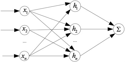
The radial basis function neural network is a three layers feed-forward neural network and has strong parameter online adjustment ability, which the input to the output are nonlinear and the hidden layer to the output layer is linear. The structure of RBF neural network is shown in Fig. 3.
In the structure of RBF neural network, X=[x1,x2⋯,xn]T is the input vector, its radial basis vector is: H=[h1,h2,⋯hj,⋯hm]T, hj is the Gaussian radial base function:
Fig. 3The structure of RBF neural network
The center vector of the jth node is: Cj=[cj1,cj2,⋯,cji,⋯,cjn], where, i=1,2,⋯,n.
The base width vector of the network is: B=[b1,b2,⋯,bm], bj are the base width parameters of j node, and it is positive. The weight vector of the network is: W=[w1,w2,⋯,wj,⋯wm].
The output of identification network is:
The performance indicator function of the identifier is:
According to the gradient descent, iterative algorithm of output weight, node center, the base width parameter is:
where, η is the learning rate; α is the factor of momentum.
The arithmetic of Jacobian matrix is:
where, x1=Δu(k).
Using the incremental PID, the control error is:
The three inputs of PID are:
The control arithmetic is:
The tuning index of neural network is:
The tuning of kp, ki and kd employed the gradient descent algorithm:
where, ∂y/∂Δu is the Jacobian information of the controlled object, which can be acquired from the identification network.
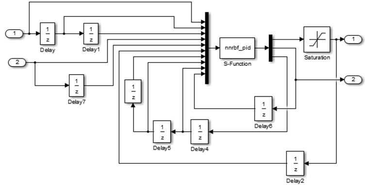
The simulation model of RBFNN PID is described in Fig. 4, RBFNN PID algorithm is fulfilled by programming S-Function of MATLAB using Eqs. (11-28). Setting the learning rate is η= 0.25, the factor of momentum is α= 0.05, the number of nodes is n= 6, the initial value of PID is [400, 5, 60], the initial weightings is W= [30, 40, 20].
Fig. 4The simulation model of RBFNN PID
3.3. The parameter design of PI control
PI control is a special case of PID control, the two parameters are kp= 40, ki= 20, which can bring about control system with the satisfactory steady state performance.
4. The design for T-S fuzzy weighted soft switch
4.1. Design principle
The output membership of T-S fuzzy inference can be linear or constant, which is suitable for expressing the dynamic characteristics of complex systems [20, 21]. The goal of T-S fuzzy weighted soft switch is to smooth the outputs of three controllers, the membership of T-S fuzzy inference can be constant, which resulting the output of fuzzy inference is constant, three coefficients of three modes are obtained from T-S fuzzy inference. According to the state informations of control system, where there is need to switch among three modes in terms of the error of rotor speed and its rate change, T-S fuzzy inference method is applied, of which defuzzification employed the method of weighted average to attain the coefficients of three modes in the switching process, the final controlled quantity adopted the weighted sum method to weight the coefficients to the three modes to smooth the outputs of three controllers, consequently , the T-S fuzzy weighted soft switch can be achieved.
This switch method differs from traditional method who only switches in a certain threshold, introducing the deviation and its derivative, and a few moments before reach the threshold, the deviation is less than the setting threshold, if the change rate of the deviation is bigger, this method of the paper just to switch. In the same way, after the arrival of the deviation, the deviation is greater than the setting threshold, if the change rate of the deviation is smaller, the method used in this paper will not switch the mode. The specific switching time is realized by T-S fuzzy inference, which also makes full use of the advantage the intelligence of fuzzy control.
Assuming MD1 is the fuzzy control mode; MD2is the RBFNN PID control mode; MD3 is the PI control mode; wa, wb and wc are the outputs of T-S fuzzy inference, that are also the coefficients of fuzzy control mode, RBFNN PID control mode and PI control mode; Ufuzzy is the output controlled quantity of fuzzy control; URBF is the output controlled quantity of RBFNN PID control; UPI is the output controlled quantity of PI control; Usum is the synthetic output of T-S fuzzy weighted multi-mode soft switch.
The fuzzy control plays a major role in large error while RBFNN PID control and PI control take tiny effect, wa is the predominant coefficient; switching to the RBFNN PID in medium error, fuzzy control and PI control act feebly at this moment, wcis the leading coefficient; in small error, PI control takes prime part while fuzzy control and RBFNN PID control attribute diminutively. Put wa, wb and wc weighted to Ufuzzy, URBF and UPI, the T-S fuzzy weighted multi-mode soft switch will be come true, which include fuzzification, fuzzy inference, defuzzification and synthetic output four procedures.
4.2. Fuzzification
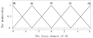
The error E and its change rate EC decided the modal division of T-S fuzzy weighted switch algorithm, which are used to confirm the coefficients of three modes of T-S inference. The domain and fuzzy domain of E and EC are set the same as fuzzy control. The T-S fuzzy inference system was built by using the fuzzy logical toolbox in MATLAB, as is shown in Fig. 5. Assuming the fuzzy subsets of E are {PS, PW, PM, PB} and EC are {NB, NS, ZE, PS, PB}. The memberships of E and EC are described in Fig. 6 and Fig. 7, the memberships of wa, wb and wcare the same which are two constants zero and one.
Fig. 5The T-S fuzzy inference system
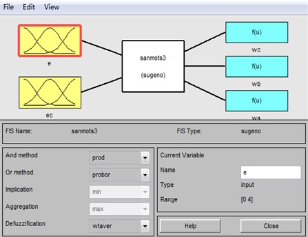
Fig. 6The membership of E
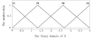
Fig. 7The membership of EC
4.3. Fuzzy inference
The weights number distributions must be considered before fuzzy inference, the weights number distributions of wa, wb and wc are described in Tables 3-5.
Table 3The weight number distribution of wa
E | EC | ||||
NB | NS | ZE | PS | PB | |
PS | S1 | S1 | S1 | S1 | S1 |
PW | S1 | S1 | S1 | S1 | S1 |
PM | S1 | S1 | S1 | S1 | B1 |
PB | S1 | S1 | S1 | B1 | B1 |
where B1= 1, S1= 0 | |||||
Table 4The weight number distribution of wb
E | EC | ||||
NB | NS | ZE | PS | PB | |
PS | S1 | S1 | S1 | S1 | B1 |
PW | S1 | S1 | S1 | B1 | B1 |
PM | B1 | B1 | B1 | B1 | S1 |
PB | B1 | B1 | B1 | S1 | S1 |
where B1= 1, S1= 0 | |||||
Table 5The weight number distribution of wc
E | EC | ||||
NB | NS | ZE | PS | PB | |
PS | B1 | B1 | B1 | B1 | S1 |
PW | B1 | B1 | B1 | S1 | S1 |
PM | S1 | S1 | S1 | S1 | S1 |
PB | S1 | S1 | S1 | S1 | S1 |
where B1= 1, S1= 0 | |||||
Table 6The description of modal fuzzy rules
E | EC | ||||
NB | NS | ZE | PS | PB | |
PS | MD3 | MD3 | MD2 | MD2 | MD2 |
PW | MD3 | MD3 | MD2 | MD2 | MD2 |
PM | MD2 | MD2 | MD2 | MD2 | MD1 |
PB | MD2 | MD2 | MD2 | MD1 | MD1 |
Assuming MD1 is mode of fuzzy control, MD2 is the mode of RBFNN PID control, MD3 is the mode of PI control for the sake of accurate description the logic of fuzzy inference. The fuzzy subsets of MD are {MD1,MD2,MD3}, the description of modal fuzzy rules is shown in Table 6.
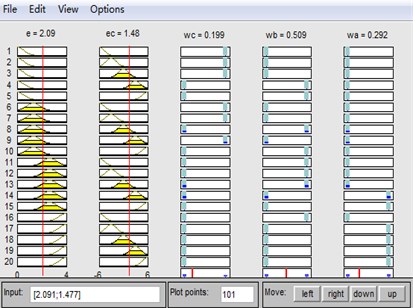
Through the ruler viewer in fuzzy logical toolbox, obviously, wa, wb and wc are satisfied to Eq. (30), as is shown in Fig. 8.
Fig. 8The ruler viewer
4.4. Defuzzification
The T-S fuzzy inference system has two defuzzification methods, that is the weighted average and the weighted sum, the weighted average method is adopted in the process of defuzzification. Assuming the output of rule i is ui, its weight is wi, m is the number of fuzzy ruler, so the total output is:
The coefficients of three modes wa, wb and wc are calculated by the above equation. The output memberships of three modes of T-S fuzzy inference were set to two constants, which values are zero and one. After fuzzification and defuzzification, the coefficients of three modes, (wa, wb and wc) are all the accurate values between zero and one. At any given moment, one of the numbers wa, wb and wc is larger, the other are relatively smaller under the given constraint condition:
4.5. Synthetic output
In the control process, put wa, wb and wc weighted to Ufuzzy, URBF and UPI, the soft switch can be fulfilled. The synthetic output of controlled quantity employed the weighted sum method:
5. Simulation
A multi-mode soft switch control model for the variable pitch of permanent magnet direct drive wind turbines model was built in MATLAB/SIMULINK to verify the performance of the proposed control scheme. The parameters of wind turbines for simulation is shown in Table 7.
Table 7The parameters of PMSG wind turbines
Rated power | 2MW | Stator resistance | 0.0024 H |
Blade radius | 46.74 m | Stator inductance | 0.0024 H |
Air density | 1.225 kg/m3 | Magnetic flux | 1.67 wb |
Blade inertia | 54894 kg⋅m2 | Pole-pairs | 60 |
Rated wind | 12 m/s | Rotor inertia | 411185 kg⋅m2 |
The PI control model, fuzzy control model and RBFNN PID control model for variable pitch were also built. The step wind which is used to verify the anti-interference performance of the proposed method and the combined wind were applied to simulate the characteristics of wind.
1) The step wind. The wind is 14 m/s during 0-5 second, suddenly changed to 19 m/sat 5 second, after remain in this status, as is shown in Fig. 9. Under the four control schemes (T-S fuzzy weighted multi-mode control, fuzzy control, RBFNN PID, PI control), the rotor speed is shown in Fig. 10, the pitch angle is described in Fig. 11, the power is shown in Fig. 12. The weight output of T-S fuzzy inference is described in Fig. 13.
Fig. 9The curve of step wind
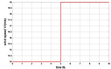
Fig. 10The comparison of rotor speed
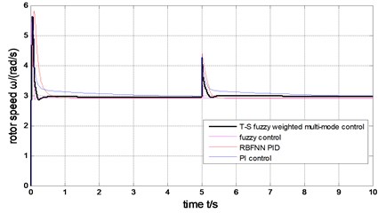
Fig. 11The comparison of pitch angle
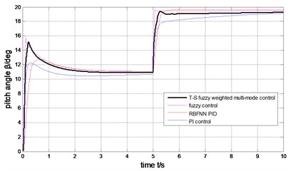
Fig. 12The comparison of generator output power
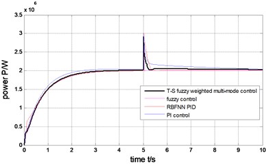
Fig. 13The weight output of T-S fuzzy inference
2) The combined wind. vn is replaced by Eq. (32) while using the combined wind:
where, vnmax is the peak of random noise component; Ram is the random value in [–1, 1]; wi and ϕi are the random value in [0, 2π]. The combined wind is shown in Fig. 14.
In the process of simulation, assuming l= 15, s= 1, vgmax= 4 m/s, t1g= 0 s, tg= 10 s, vrmax= 1 m/s, t1r= 0 s, tr= 10 s, t2r= 10 s, vnmax= 2 m/s.
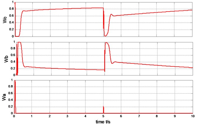
Under the four control methods (T-S fuzzy weighted multi-mode control, fuzzy control, RBFNN PID, PI control), the rotor speed is shown in Fig. 15, the pitch angle is described in Fig. 16, the power is shown in Fig. 17. The weight output of T-S fuzzy inference is described in Fig. 18.
Fig. 14The curve of the combined wind
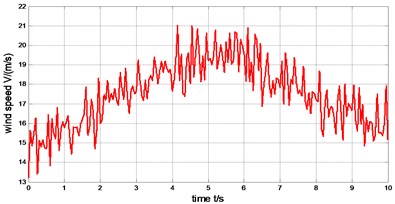
Fig. 15The comparison of rotor speed
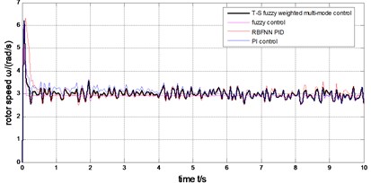
Fig. 16The comparison of pitch angle
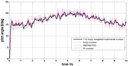
Fig. 17The comparison of generator output power
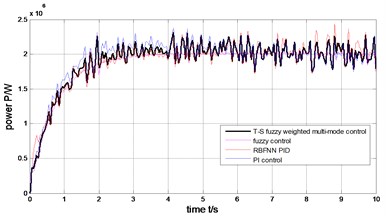
Fig. 18The weight output of T-S fuzzy inference
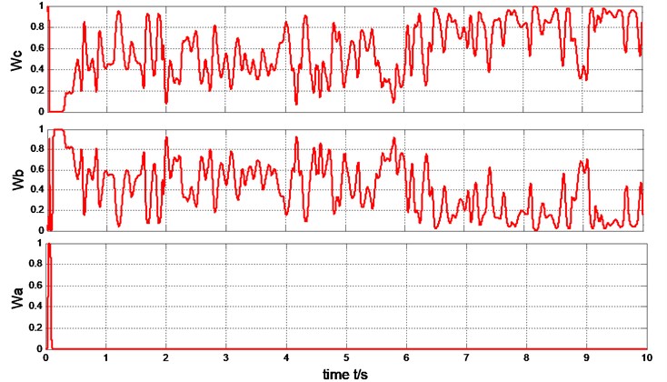
The output power of the generator can be limited to rated value (2MW) under the step wind and the combined wind by the four methods presented in Fig. 17 and Fig. 12. Under the step wind, after system reached steady state, exerted a disturbance at 5th second, better anti-jamming capability of T-S fuzzy weighted multi-mode control than RBFNN PID and PI control are shown in Fig. 10, Fig. 11 and Fig. 12. Under the combined wind, an actual and complex wind condition, the power and rotor speed have the smaller fluctuation by using the fuzzy control of single model, when the wind changed, the pitch angle response is too quick with larger overshoot magnitude and fluctuation resulting the pitch actuator acts frequently and the increasing fatigue load of all parts of wind turbines. The precision of the pitch angle response is low, and the response speed is slow by using PI control, as the deviation gets bigger and bigger in 0-5 s, the fluctuation of rotor speed and power is bigger than RBF PID. The rapidity of pitch Angle response is bad by using RBFNN PID, as the deviation gets smaller and smaller in 6-10 s, the fluctuation of rotor speed and power is bigger than PI control. The response of pitch angle is adjusted more smoothly and quickly with higher precision and smaller fluctuation by using the T-S fuzzy weighted multi-mode control compared to the others as seen in Fig. 16, the rotor speed and power close to RBFNN PID during 0-5 s and to PI control during 6-10 s described in Fig. 15 and Fig. 17, the higher precision guarantees the output power of the generator stabilize to rated power and smaller fluctuation reduce the mechanical fatigue load of wind turbines. To sum up in conclusion, the proposed method has better control performance than other methods, it can not only stabilize the output power of wind turbines but also reduce the fatigue load. The Eq. (30) is demonstrated by Fig. 13 and Fig. 18.
6. Conclusions
The constant power operation of the wind turbines over rated wind speed caused the pitch actuator act frequently and the increasing fatigue load of parts of wind turbines, which affected the quality of the output power and the service life of wind turbines in the existing variable pitch control schemes. In order to deal with these problems, the T-S fuzzy weighted multi-mode soft switching variable pitch control which was a novel strategy was proposed for permanent magnet direct drive wind turbines. Multi-mode control is introduced, which takes account of the advantages of fuzzy control, RBFNN PID control and PI control. The T-S soft switch is designed for the oscillation problem of mode switch, which based on T-S fuzzy inference to smooth the outputs of three controllers to accomplish soft switch and uses the intelligence of fuzzy control.
The simulation results show the integrated control performance of the proposed scheme is superior to the others. Better anti-jamming ability is shown under the step wind. Under the combined wind, an actual and complex wind condition, the response of pitch angle is adjusted more smoothly and quickly with higher precision and smaller fluctuation compared to the others, which reduce fatigue load of permanent magnet direct drive wind turbines. The rated rotor speed and power can be rapidly tracked witch lower fluctuation. For the pulsation of output power, it can be solved by adding back-to-back inverter to the wind turbine. This strategy has a certain reference value for the constant operation of permanent magnet direct drive wind turbines above the rated wind.
References
-
Krishnama R. S., Pillai G. N. Design and real time implementation of type-2 fuzzy vector control for DFIG based wind generators. Renewable Energy, Vol. 88, 2016, p. 40-50.
-
Camblong H., Nourdine S., Vechiu I., Tapia G. Control of wind turbines for fatigue loads reduction and contribution to the grid primary frequency regulation. Energy, Vol. 48, 2012, p. 284-291.
-
Nguyen D., Fujita G. Analysis of sensorless MPPT method for hybrid PV-Wind system using DFIG wind turbines. Sustainable Energy, Grids and Networks, Vol. 5, 2011, p. 50-57.
-
Li C. B., Liang J. Y., Zhao M., Zheng P. P. Simulation research on pitch control strategies of variable pitch wind turbine within the whole section of wind speed. Journal of Electric Machines and Control Applications, Vol. 42, Issue 3, 2015, p. 56-60.
-
Chiang M. H. A novel pitch control system for a wind turbine driven by a variable-speed pump-controlled hydraulic servo system. Mechatronics, Vol. 21, Issue 4, 2011, p. 753-761.
-
Yuan Y., Tang J. Adaptive pitch control of wind turbine for load mitigation under structural uncertainties. Renewable Energy, Vol. 105, 2017, p. 483-494.
-
Lin W. M., Hong C. M., Ou T. C., Chiu T. M. Hybrid intelligent control of PMSG wind generation system using pitch angle control with RBFN. Energy Convers Manage, Vol. 52, Issue 2, 2011, p. 1244-1251.
-
Liu J., Yang H. Q. Application research of wavelet neural network and PID in maximum power point tracking of wind power system. Journal of Industrial Automation, Vol. 39, Issue 12, 2013, p. 73-76.
-
Nam Y., Kim J., Paek I., Moon Y. H., Kim S. J., Kim D. J. Feedforward pitch control using wind speed estimation. Journal of Power Electronics, Vol. 11, Issue 2, 2014, p. 211-217.
-
Yin M., Li G. Y., Zhang J. C., Zhao W. R., Xue Y. F. Modeling and control strategies of directly drive wind turbine with permanent magnet synchronous generator. Power System Technology, Vol. 31, Issue 15, 2007, p. 61-65.
-
Yin X. X., Lin Y. G., Li W., Gu Y. J., Liu H. W., Lei P. F. A novel fuzzy integral sliding mode current control strategy for maximizing wind power extraction and eliminating voltage harmonics. Energy, Vol. 85, 2015, p. 677-686.
-
Yao X. J., Liu S., Shan G. K., Xing Z. X., Guo C. C., Yi C. B. LQG controller for a variable speed pitch regulated wind turbine. Intelligent Human-Machine Systems and Cybernetics, Vol. 2, 2009, p. 210-213.
-
Moradi H., Vossoughi G. Robust control of the variable speed wind turbines in the presence of uncertainties: a comparison between H∞, and PID controllers. Energy, Vol. 90, Issue 2, 2015, p. 1508-1521.
-
Wang B., Qin S. Backstepping sliding mode control of variable pitch wind power system. Power and Energy Engineering Conference, Asia-Pacific, Vol. 28, Issue 31, 2010, p. 21-23.
-
Qin B., Zhou H., Du K., Wang X. Sliding mode control of pitch angle based on RBF neural-network. Transactions of China Electrotechnical Society, Vol. 28, Issue 5, 2013, p. 37-41.
-
Ren L. N., Lv M. M., Wang Z. C. Improved bee colony algorithm on the wind turbine pitch control. Machinery Design and Manufacture, Vol. 36, 2015, p. 43-46.
-
Zhou F. H., Liu J. Fuzzy control strategy of direct-drive wind power system based on state feedback. Power System Technology, Vol. 40, Issue 19, 2016, p. 2758-2763.
-
Anderson P. M., Bose A. Stability simulation of wind turbine systems. IEEE Transactions on Power Apparatus and Systems, Vol. 102, Issue 12, 1983, p. 3791-3795.
-
Yang B., Jiang L., Wang L., Yao W., Wu Q. H. Nonlinear maximum power point tracking control and modal analysis of DFIG based wind turbine. International Journal of Electrical Power and Energy Systems, Vol. 74, 2016, p. 429-436.
-
Zhu H. Y., Zhang Q. J., Shen L. C. Design and simulation of multi-mode transition controller based on fuzzy weight. Journal of System Simulation, Vol. 19, Issue 18, 2007, p. 4212-4215.
-
Tang N., Xiao X. N., Chen Z. A method of multi-mode switching for SVC based on Sugeno fuzzy inference. Power System Technology, Vol. 35, Issue 8, 2011, p. 140-143.
About this article
This work is supported by Natural Science Foundation of Gansu Province of China (Grant No. 1606RJZA002) and Universities Scientific Research Project of Gansu Province (Grant No. 2017A-026).

