Abstract
The effect of dynamic performance shall be considered when calculating the wind speed relative to the wind turbine structure, since it is essential to prolong its service life. This article presents a method to get dynamic responses of a wind turbine under different conditions. The time-varying load acting on the blade is calculated by using the blade element momentum theory, and the dynamic performance of the wind turbine are calculated by applying the modal superposition method with blade loads as excitations. A platform is constructed to experimentally test the dynamic responses of the wind turbine system. The dynamic response process is adopted to carry out a dynamic analysis, and theoretical results are compared with experimental results, indicated that the analysis presented in this paper is correct. In addition, the 2 MW wind turbine operating in different wind fields is analyzed by applying the computing method. The results indicate that the wind turbine experiences a huge transverse vibration under turbulent wind, the hub vibration is intensified up to 179.52 %, and the vibration of the blade tip intensifies up to 190.41 % under the action of gusts in extreme conditions relative to the steady state, which shall be considered during design.
Highlights
- This article presents a computing method to get dynamic responses of a wind turbine under different conditions.
- A platform is constructed to experimentally test the dynamic responses of the wind turbine system. And the results proved that the computing method presented in this paper is correct.
- The 2 MW wind turbine operating in different wind fields is analyzed by applying the computing method.
1. Introduction
Due to that the global energy shortage and environmental pollution, wind energy has been attracting a growing amount of attention as a type of clean and renewable energy source [1]. Since natural wind is variable in time and space, wind generating sets are subject to frequent disturbances and dynamic load excitations, resulting in strong vibrations which are detrimental to its operating performance and service life. With the incessant development of the wind power industry, wind generating sets must be increased in size and power, in order to make their dynamic performance more complex [2]. Accordingly, when wind turbines are subject to dynamic analysis, it is necessary to analyze their dynamic performance in various conditions.
In a recent research work on the dynamic performance test of wind turbines, Javad Baqersad adopted the stereophotogrammetry to measure the dynamic strain of the wind turbine impeller [3]. Yoonsu Nam built an experimental platform for a wind turbine hub and nacelle and adopted the Kalman filtering method to estimate the displacement response of the nacelle [4]. Li Ming adopted a similar model for a 1.5 MW wind generating set blade and simulated a natural wind field by a vehicle carrying test system, to obtain load data from every section of the blade and the output power of the set, being consistent with BLADED simulation results to a great extent [5]. Since the wind turbine is in an extreme environment, with blade rotor diameters up to hundreds of meters in magnitude and requiring long test periods, a limited number of research works have been carried out on the dynamic performance of wind turbines.
In terms of theoretical research on this field, Murtagh investigated the coupling between the tower and the wind load, carrying out the corresponding forced vibration analysis [6]. Liu Xiong analyzed the dynamic performance of a wind turbine in turbulent condition and demonstrated that centrifugal stiffening and aerodynamic damping of blades had a great influence on its dynamic response [7]. Mohammad-Amin Asareh built a dynamic response simulation platform for a 5 MW wind turbine to simulate the dynamic response of a wind turbine in normal and seismic conditions, and analyzed the difference in dynamic response between different conditions [8]. Lv Jinan has studied a simplified blade and tower of a MW wind generator, determining the displacement response of a wind turbine in start-up and analyzing the influence of the geometric nonlinearity of blade on the dynamic response of the wind turbine [9]. Wu Pan worked with AroeDyn and FAST software to set up a simulation model for the wind turbine and analyzed the dynamic performance of a wind turbine in five different turbulent conditions based on aerodynamics [10]. However, the analysis objects in these works are individual parts such as the blade and the tower; in addition, almost no literature is available concerning the transient response of wind turbines in complex conditions.
In this paper, a dynamic performance calculation method is proposed based on the mode superposition method. A numerical analysis and experimental tests are carried out on an experimental prototype of wind turbine, indicating that the calculation method presented in this paper is accurate. The method has been adopted to analyze the dynamic performance of a 2 MW large wind turbine in start-up, normal shut-down, standard turbulence and limit gust conditions.
2. Aerodynamic load calculation base for wind turbine
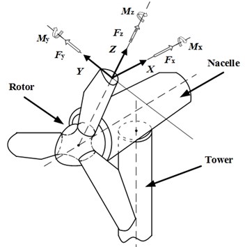
A wind turbine is primarily composed of blades, hub, nacelle, tower and drive system. The wind turbine draws wind energy through blades to sustain the movement of a wind rotor and convert wind energy into mechanical energy by a drive system. Therefore, blades are the leading component under stress in the operating system [11]. The loads applied to the blade mainly include aerodynamic force, centrifugal force and gravity. Fig. 1 shows the coordinate system employed for the loads and the deflection of blades, in which, is the windward direction, the axis is along the length of the blade, and the axis is determined by rule of the right hand.
Fig. 1Coordinate system for blade loads and deflections.
The document [7] integrates the actions of aerodynamic load, gravity and centrifugal force acting on blades, in order to determine the overall load per unit length applied to the formulas:
where: and are aerodynamic load per unit length; , and are blade gravity forces per unit length; and are centrifugal forces of blade per unit length. Since the impeller of wind turbine analyzed in the paper is stationary, the windward load on blade shall be the primary load.
3. Theory and calculation of dynamic performance of wind turbine
3.1. Fundamental theory on mode superposition method
The most commonly used dynamical methods include the multi-body dynamics method (MBS), finite element method (FES), modal analysis method and continuous system (COS). Among these, the finite element method and the modal analysis method are most frequently adopted to the dynamics of wind turbines [12, 13]. The finite element method is adopted to make a study of the dynamic performance of a wind turbine; the basic idea is to repeatedly utilize a transient analysis to determine the steady response of the structure under the action of a periodical excitation. The transient analysis can be performed in terms of a full transient analysis, reduced transient analysis and mode superposition method for the solution. The full transient analysis requires a large amount of calculations and an accordingly longer time, whereas the reduced transient analysis is unable to find the applied unit loads, since all the loads are applied only to a user-defined master degree of freedom. The mode superposition method extracts the master mode set of the structure (master matrix) to form the coordinate transformation matrix for the transformation and reduction of its order.
Wind turbines are characterized by a longer time for load bearing and by complex frequency components; therefore, we have adopted the mode superposition method to obtain the dynamic response of the wind generating set. Compared with other methods, this approach uses fewer degrees of freedom to carry out a reliable simulation of the dynamic behavior of the wind turbine with faster calculation speed and high efficiency. Under the action of a time-varying load, the equation of motion for a multiple-degree of freedom wind turbine can be written as follows:
where is the mass matrix; is the damping matrix; is the stiffness matrix; is the node acceleration vector; is the node speed vector; is the node displacement vector.
is the modal matrix of the system, the coordinate transformation is as follows:
Forced vibration equation of system:
Eq. (4) is multiplied by the characteristic mode of vibration to obtain:
has orthogonality, the equation under principal coordinate:
According to the orthogonality of principal mode of vibration, we can obtain:
where is the damping ratio of th order modal shape; is the frequency of the th order modal shape, .
Eq. (7) is substituted into Eq. (6) to obtain the second order differential equation:
After the displacement component on every modal coordinate is solved, the displacement response at every node degree of freedom shall be obtained by the mode superposition method:
3.2. Dynamic response calculation process for wind turbine
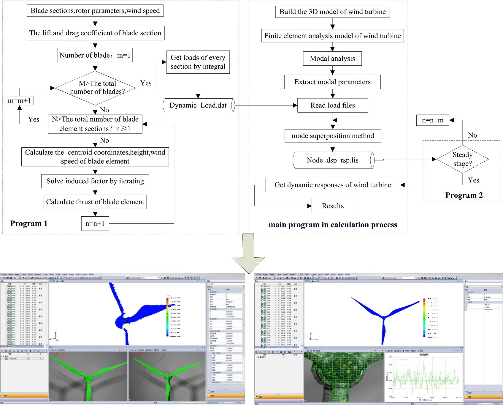
The calculation method for the dynamic responses of wind turbines takes the finite element as a platform and the secondary development language APDL for the solution. The detailed analysis process is shown in Fig. 2.
Fig. 2Calculation process for dynamic performance of wind turbine
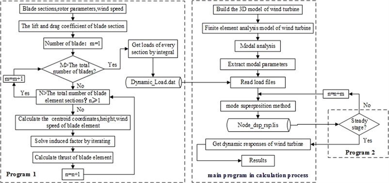
“Program 1” in the calculation process adopts the theorem of momentum for the blade element to calculate the aerodynamic force acting on the blade. This includes the calculation of the blade aerodynamic performance and the calculation of the velocity induced factor iteration. The document [14] elaborates a calculation process for the aerodynamic force on the blade, this paper gives no unnecessary details; the main program in the calculation process express the windward dynamic loads of the blade into ANSYS by APDL and disperses them into an impulsive load one, storing them in the textual form and then adopting the mode superposition method to find the dynamic response of the wind turbine; if the wind turbine is subject to a steady state analysis, “program 2” is adopted in the calculation process to determine whether the steady state phase is actually reached. The allowed error in the solution period is : if the requirement of Eq. (10) is satisfied, the wind turbine has reached a steady response state, and the calculations can be terminated at this point [15]:
where: is the allowable error given in the period; is the displacement value of wind turbine on the th node at the last moment; is the displacement value of wind turbine on the th node at the initial moment.
4. Calculation method verification
Since the true prototype of a wind turbine can reach a width of hundreds of meters, it is very difficult to experimentally test the dynamic performance of an actual prototype of a wind turbine. In order to verify the validity of the calculation methods, a test platform for the dynamic response of the wind turbine prototype was built, with a digital speckle strain measurement system (XTDIC) from the Xi’an Jiaotong University, adopted for the measurement of the dynamic performance of the wind turbine. The XTDIC system is an optical non-contact three-dimensional deformation measurement system, with the measurement accuracy up to 10 μm which ensures the accuracy of the tests performed on the wind turbine.
The test platform for the dynamic response of wind turbine is shown in Fig. 3. It is composed of an axial flow fan, anemoscope, XTDIC measurement system, wind turbine and its base. The function of the axial flow fan consists in providing a wind source for the test platform. Wind speed changes by changing its rotary speed in the experimental process; the anemoscope is used to measure the wind speed; the digital speckle strain measurement system is adopted to measure the wind force and the dynamic response of every component of the set; the test model for the wind turbine is composed of blades, a hub, a tower and a fixed nacelle connected to the tower. The blade and the hub are installed inside the nacelle by bearing supports; the test model for the wind turbine is placed on the base to regulate the posture of the wind turbine: by rotating the base, the varying wind direction can be simulated.
Fig. 3Test platform of dynamic response of wind turbine

The calculation results for the dynamic response of the wind turbine are employed in the dynamic analysis of the test model of the wind turbine (Fig. 4), in order to compare the simulation predictions with experimental results. Table 1 shows the displacement dynamic response of the wind turbine hub under the action of various steady state winds; the error between simulation and experimental results is as low as 5.56 % when the wind speed is 12 m/s; the highest error between the calculated value and the test value is 8.67 % at the wind speed of 8 m/s; the table shows that test values are generally lower than analysis values, probably due to the influence of spray painting of the speckle on the test result. The error between calculated values and experimental values is smaller than 10 % at any wind speeds, indicating that the employed analysis method is valid.
Fig. 4Test results of wind turbine dynamic response
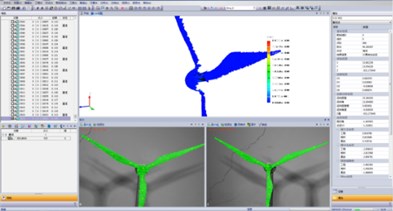
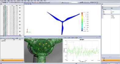
Table 1Comparison between numerical analysis results and test results
Wind speed / m·s-1 | 8 | 10 | 12 | 14 | 16 |
Test results /mm | 11.79 | 17.58 | 21.59 | 14.16 | 11.53 |
Numerical analysis results / mm | 12.91 | 18.71 | 22.86 | 15.11 | 12.42 |
Error / % | 8.67 | 6.03 | 5.56 | 6.29 | 7.17 |
5. Case studies
5.1. Finite element model for wind turbine
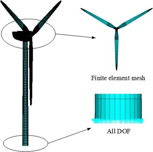
In order to perform an actual case study, a land-based 2 MW wind turbine was chosen as the analysis object. The impeller diameter is 40 m, the hub diameter is 2.5 m, and the tower height is 75 m. The blade structure in a finite element model for the wind turbine is a beam element, and the tower top mass is a point mass element. The blade material is a GRP complex fiber, with an elastic modulus of 1.76×10¹⁰ Pa and a Poisson ratio of 0.17; the tower is made of Q345E alloy steel, which elastic modulus is 2.06×10¹¹ Pa, and which Poisson ratio is 0.28. The tower bottom section is subject to full restraint to restrict all degrees of freedom on the section node. The finite element analysis model for the wind turbine is shown in Fig. 5: the number of element nodes is 63,377, and the number of elements is 292,296.
Fig. 5Finite element analysis model for wind turbine
5.2. Modal analysis
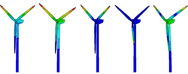
Modal analysis is the basis for the dynamic response analysis process. In this work, a Block Lanczos method algorithm was adopted to carry out a modal analysis of a wind turbine system to extract the natural frequency at first 20 orders of structure, as shown in Table 2. Due to space limitations, we only present the mode shapes at the first five orders, as shown in Fig. 6.
Table 2Modal results of wind turbine system
Order | Frequency / Hz | Order | Frequency / Hz | Order | Frequency / Hz |
1 | 0.23891 | 8 | 2.2167 | 15 | 4.8451 |
2 | 0.28092 | 9 | 2.6287 | 16 | 7.6681 |
3 | 0.30279 | 10 | 2.7862 | 17 | 7.7101 |
4 | 0.30987 | 11 | 3.4941 | 18 | 7.8028 |
5 | 0.54802 | 12 | 3.9306 | 19 | 8.5290 |
6 | 0.70261 | 13 | 4.0094 | 20 | 8.7435 |
7 | 1.8022 | 14 | 4.7662 |
From the modal shape diagram (Fig. 6) of the wind turbine, it is possible to observe that the first order mode shape is forward and backward bending vibration of two blades along the axis; the second order mode shape is forward and backward bending vibration of the whole wind turbine along the axis, the third, fourth and fifth order modal shapes are the first order flap vibrations of the blade. In the third order mode, the lower blade remains motionless while the remaining two blades undergo reverse vibrations along the axis; in the fourth order mode, the lower blade undergoes a reverse vibration along the axis; finally, in the fifth order mode, three blades vibrate along the axis.
Fig. 6Modal vibration modes of wind turbine (from 1st to 5th order)
5.3. Analysis of steady dynamic performance of wind turbine
The dynamic excitation of the wind turbine blade and hub at a rated wind speed of 10 m/s is obtained by calculations shown in Fig. 7 and Fig. 8. The exciting load of the blade shows periodical changes between 33.72×10³ N and 46.69×10³ N, the load frequency component contains a 0.3 Hz dominant frequency component, plus its double and triple values; the hub load shows periodical changes between 266.25×10³ N and 274.74103 N, its load frequency is composed of a 1/3 sub harmonic, a 0.9 Hz dominant frequency component and its double value.
Fig. 7Dynamic excitation at position 2/3 of blade at constant wind speed of 10 m/s

a) The curve of dynamic load

b) The spectrum of dynamic load
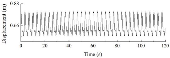
The dynamic response curve of hub displacement on the wind turbine can be obtained by analyzing the steady state dynamic response of the wind turbine based on the calculation process shown in Fig. 9. The hub displacement response fluctuates between 0.55 m and 0.80 m; the dominant frequency component in the dynamic response is 0.30 Hz, which is compatible with the dominant frequency of the blade.
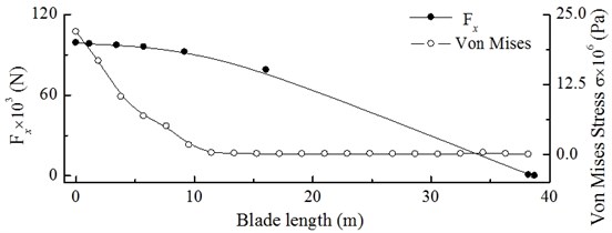
Fig. 10 shows the Von Mises stress contour of the wind turbine when the dynamic response of the hub reaches its maximum. The stress decreases linearly when moving from the bottom to the top of the tower, because the maximum stress occurs at the bottom, and the average stress value is 152.5×10⁶ Pa (Fig. 11); at the lower blade root, the stress reaches the maximum value among blades, and the average stress value is up to 35.5×10⁶ Pa; the dynamic load excitation and the Von Mises stress from the root to the tip of the blade are shown in Fig. 12. The dynamic load excitation decreases parabolically when moving from the root to the tip; since the blade can be considered as a cantilever beam, the Von Moses stress accordingly decreases as a parabola when moving from 0 to 11 m, and it follows a gradual decrease with insignificant changes from 11 to 38.75 m.
Fig. 8Dynamic excitation of hub at constant wind speed of 10 m/s

a) The curve of dynamic load

b) The spectrum of dynamic load
Fig. 9Dynamic response of displacement of hub at constant wind speed of 10 m/s
a) Dynamic response

b) The spectrum of dynamic response
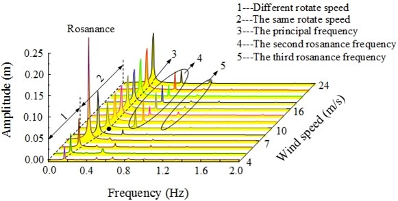
Under the action of a steady state wind, the load applied to the wind turbine is expected to change with the change of wind speed. The dynamic system characteristic is subject to the influence of the dynamic load excitation, and its response depends on the natural frequency of system. The dynamic response of the wind turbine was determined at various wind speed values shown in Fig. 13. When the wind speed is lower than the rated wind speed (10 m/s), the rotary speed of the impeller increases with the wind speed, and the wind turbine is in a speed-up stage. Since there is a linear relation between the rotary speed and frequency, the dominant frequency component of the hub dynamic response increases as well; at a wind speed of 4 m/s, the rotor speed is lower, and the fluctuations in the hub dynamic response of displacement are low, with an amplitude of 0.03 m; and the dominant frequency component is 0.169 Hz; At the wind speed of 7 m/s, the rotor speed is up to 13.3 rpm, its rotational frequency is 0.22 Hz, which is close to 0.24 Hz as the first-order natural frequency of the wind turbine system. Therefore, the wind turbine is subject to resonance, its vibration intensifies up to the amplitude of 0.24 m; in addition to the increase in the wind speed, the load frequency gradually diverges from the resonance range, and the amplitude is also decreasing.
Fig. 10Stress contour of wind turbine at constant wind speed of 10 m/s
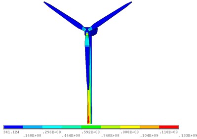
Fig. 11Von Mises stress of tower bottom and blade root at constant wind speed of 10 m/s
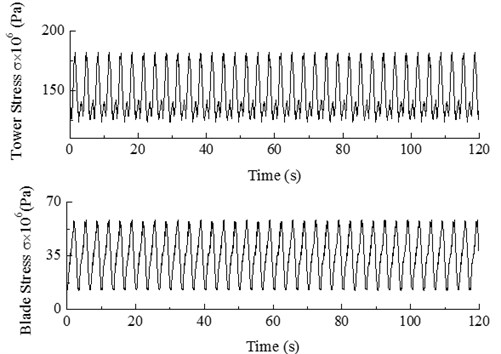
Fig. 12Dynamic load excitation and Von Mises stress from blade root to blade tip at constant wind speed of 10 m/s
When the wind speed is 9 m/s, the amplitude decreases to 0.06 m, and the dominant frequency is 0.29 Hz. If the wind speed equals the rated value of 10 m/s, the amplitude is up to 0.068 m, and the dominant frequency component is 0.30 Hz. When the wind speed exceeds its rated value (10 m/s), the rotary speed of the wind turbine impeller stops increasing, the wind turbine is in a constant speed stage, therefore, the dominant frequency component of the hub dynamic response accordingly stops increasing. In addition, the wind turbine is under variable pitch control, in order to reduce the amount of wind energy lost to changes of the pitch angle and to reduce the axial thrust. Accordingly, the amplitude of the dynamic response of the hub remains unchanged.
Fig. 13Waterfall curves for dynamic response of wind turbine hub
6. Dynamic response analysis for wind turbine in start-up and normal shut-down conditions
6.1. Dynamic response analysis for wind turbine in start-up condition
During the start-up condition, wind turbines gradually start to accelerate from a static or idling condition under the action of the aerodynamic rotor force due to natural wind speed or to a motor-applied torque, until the required speed is reached, and the generator can be connected to the grid. The start-up condition is defined as the operating condition from a static state until the rated speed is reached; Fig. 14 shows the dynamic load excitation of the hub on the wind turbine. The dynamic response curve of hub displacement in the start-up condition can be calculated as shown in Fig. 15.
Fig. 14DLC3.1 Hub load in start-up condition
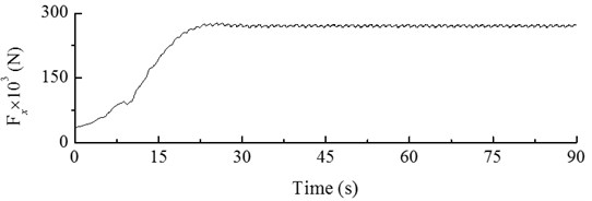
Fig. 15DLC3.1 Dynamic response of displacement of hub in start-up condition
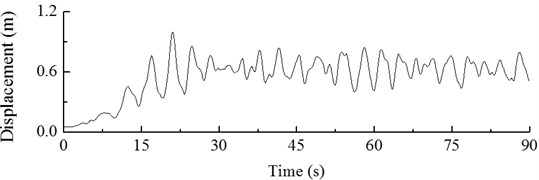
The Figures show that the load applied to hub increases throughout the start-up process, along with its displacement response. The maximum value is reached at 21 s. The dynamic response of hub displacement has a maximum value of 1.00 m. At later times, fluctuations start to occur, and after 30 s, the dynamic response of hub displacement becomes steady along with the load.
6.2. Dynamic response analysis for wind turbine in normal shut-down condition
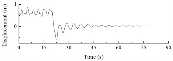
Under the action of pneumatic brakes and due to the generator resistance, the speed of wind turbine decreases until the shut-down or idling condition is reached. The dynamic load excitation applied to the hub in a normal shut-down process is shown in Fig. 16. From 0 to 20 s, the wind turbine is operating normally, and then the dynamic loads applied to the hub suddenly decrease all of a sudden at 20 s. The minimum load of –84,743 N is applied at 23 s, and then the load gradually increases to 0. The dynamic response of hub displacement obtained by calculation is shown in Fig. 17, which shows periodical changes from 0 to 20 s. Then the hub displacement decrease until the minimum value of –0.58 m at 23 s, with an increase in fluctuation amplitude by 171.96 %. This effect has a strong impact on the wind turbine; at later times, under the action of structural damping, the dynamic response of hub displacement gradually tends to 0.
Fig. 16Load applied to hub in normal shut-down condition

Fig. 17Hub response in normal shut-down condition
7. Transient response analysis for wind turbine in extreme condition
7.1. Turbulence effect
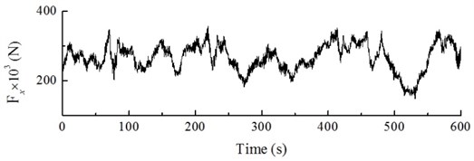
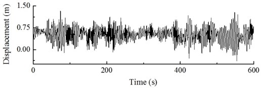
In general, turbulence is referred to as a flow regime which occurs at high flow rates, and they are in their turn accompanied with that the pressure and flow velocity of a fluid change chaotically, as opposed to what happens in a laminar flow. Turbulence in aerodynamics indicates fluctuations with a wind speed no lower than ten minutes which cannot be expressed by a definite equation. Turbulence is simulated by a wind field with the rated wind speed of 10 m/s and turbulence intensity of 18 %. The dynamic load excitation of the wind turbine hub is shown in Fig. 18. The dynamic response of the hub and of the blade tip under the action of turbulence can be obtained by calculations shown in Fig. 19 and Fig. 20.
Fig. 18 shows that, under the action of turbulence, the change in dynamic load excitation of the hub is irregular and fluctuating, the frequency component of the excitation is a low order frequency with the dominant component being at 0.9 Hz. Figs. 19 and 20 shows that, under the action of turbulence, the displacement response of the hub and the blade tip is also randomly distributed, the hub amplitude varies from –0.39 to 1.39 m, and the blade tip amplitude varies from –1.82 to 4.69 m, with a high fluctuation amplitude; in this case, the dominant frequency component of the hub is 0.29 Hz and the dominant frequency component of the blade tip is 0.30 Hz.
Fig. 18Dynamic load excitation of hub in windward direction under turbulence
a) The curve of dynamic load

b) The spectrum of dynamic load
Fig. 19Dynamic response of wind turbine hub under action of turbulence
a) The curve of dynamic response

b) The spectrum of dynamic response
Fig. 20Dynamic response of blade tip of wind turbine under action of turbulence

a) The curve of dynamic response

b) The spectrum of dynamic response
7.2. Action of gusts in extreme conditions
A gust is defined as a wind condition in which the speed fluctuates within a short time interval, as a result of air disturbances, bringing about irregular vortexes due to obstacles (e.g hills, buildings or forests) which block the air flow. The presence of vortexes changes the air flow rate, depending on the relative direction of the vortex and the air flow direction. If the vortex is consistent with air in terms of flow direction, an extremely high wind speed is generated in a short time, which is referred to as a gust in extreme conditions [16].
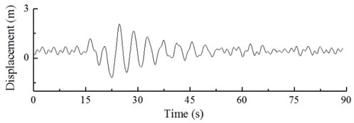
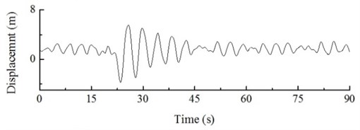
The dynamic load excitation of a wind turbine hub under the action of a gust in extreme conditions is illustrated in Fig. 21, which shows that the dynamic load excitation of the hub suddenly decreases and then increases abruptly, after that it decreases again before stabilizing to the initial value. The dynamic displacement response of the hub and the blade tip is obtained by calculations as shown in Fig. 22.
Fig. 21Dynamic load excitation of wind turbine hub under action of gust
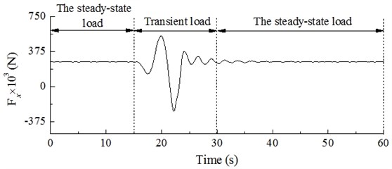
Fig. 22Dynamic response of hub and blade tip of wind turbine under action of gust
a) The curve of dynamic response
b) The spectrum of dynamic response
Figs. 21 and 22 indicate that under the action of steady state wind (0-15 s), the dynamic load excitation of the hub structure shows periodical changes between 266.35×10³ N and 274.74×10³ N, with a displacement response fluctuating between 0.55m and -0.80 m. Under the action of a gust (15-30 s), the hub load changes significantly, with the maximum load of 544.56×10³ N and the minimum load of –262.49×10³ N; the hub vibration is strongly enhanced, with a maximum amplitude of 1.84 m, which corresponds to a 179.52 % increase compared to the steady state. After the gust vanishes, the dynamic load excitation and displacement response of the hub stabilize gradually. Under the action of steady state wind, the displacement response of the blade tip is fluctuates between 0.76 m and 2.92 m, while under the action of the gust, the amplitude of the blade tip is 5.56 m at maximum, (190.41 % increase compared with the steady state). After the gust vanishes, the displacement response of blade tip stabilizes gradually as well.
7.3. Gust action with extreme direction changes
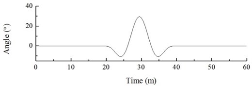
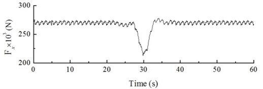
When the wind turbine is in operation, gusts may make the wind direction change in the form of a cosine while keeping a constant speed. These conditions are referred to as gusts with extreme direction changes. Fig. 23 shows the dynamic load excitation of the wind input model and the wind turbine hub, which transient response curve is shown in Fig. 24.
Fig. 23Gust (change in direction) direction change diagram and dynamic load excitation of hub
a) Wind direction
b) The curve of dynamic load
Fig. 24Dynamic response of hub under action of gust (change in direction)
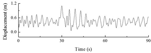
Figs. 23 and 24 show that, when the angle between the wind direction and the turbine is 0° (0-20 s), the dynamic load excitation of the wind turbine hub shows periodical changes between 266.35×10³ N and 274.74×10³ N, and its displacement response fluctuates between 0.55 m and 0.80 m. When the angle between the wind direction and the turbine starts to vary (20-40 s), the load and displacement response of the hub also change; the angle at 30 s reaches its maximum value of 40°. At this point, the windward load applied to the wind turbine rapidly decreases, and the dynamic load excitation of the hub decreases to its lowest value of 216.04×10³ N. The maximum amplitude in these conditions is 1.10 m, which is lower by 137.5 % as compared with the steady state. As the angle gradually decreases (from 30 s to 40 s), the dynamic load excitation of the hub increases, and its displacement response fluctuation decreases. The transient gust vanishes at 40 s, when the angle is 0. The dynamic response of hub displacement stabilizes along with the dynamic load excitation. Due to the flexibility of wind turbine blades, the gust with extreme direction has very small influence on the blade tip, which is not considered here for this reason.
8. Conclusions
This work presents a calculation method for the dynamic response analysis of a wind turbine, determining its dynamic response in various conditions. The following main conclusions can be draw from our results:
1) Under the action of steady state wind, if the wind speed is lower than its rated value, the rotary speed of the wind turbine increases, as does the dominant frequency component of its hub displacement response. In the case of rated wind speed, the Von Mises stress at the tower bottom has its maximum, with the average value up to 152.5×10⁶ Pa; at a higher wind speed, the turbine is in constant speed operation, the dominant frequency component of the hub displacement response is consistent with the value found at the rated wind speed, without further increase.
2) In the start-up condition, the dynamic response of hub displacement of the wind turbine increases: after reaching its peak value, it gradually stabilizes, affecting on the wind turbine to a certain extent. In the normal shut-down condition, the minimum amplitude of the wind turbine hub is higher by a factor of 171.96 % as compared with the steady state, shortening the service life of the wind turbine.
3) Under the action of turbulence, the displacement response fluctuation at the hub and the blade tip of the wind turbine is enhanced and irregular, the dominant frequency component of the hub displacement response is 0.29 Hz, and the dominant frequency component of the blade tip is 0.30 Hz.
4) Under the action of gusts in extreme condition, the maximum amplitudes of the wind turbine hub and the blade tip are increased by 179.52 % and 190.41 %, respectively, with respect to the steady state; under the action of gusts with extreme direction changes, the maximum amplitude of the wind turbine hub is increased by 137.5 % as compared with the steady state, while the displacement response of the blade tip is virtually unaffected due to the blade flexibility.
References
-
Marin J. C., Barroso A., Paris F., et al. Study of fatigue damage in wind turbine blades. Engineering Failure Analysis, Vol. 16, Issue 2, 2009, p. 656-668.
-
He Jing, He Yuling, Jin Xing, et al. Vibration analysis and system simulation for stalled wind turbine. Journal of Chongqing University (Natural Science Edition), Vol. 30, Issue 5, 2007, p. 91-95.
-
Javad Baqersad, Christopher Niezrecki, Peter Avitabile Full-field dynamic strain prediction on wind turbine using displacements of optical targets measured by stereophotogrammetry. Mechanical Systems and Signal Processing, Vol. 62, Issue 63, 2015, p. 284-295.
-
Yoonsu Nam, Tai Jun Yoon Laboratory-scale experiments on wind turbine nacelle movement estimation. Mechanical Systems and Signal Processing, Vol. 23, 2009, p. 2435-2444.
-
Li Ming, Tian De, Wang Haikuan, Han Qiaoli, Ma Guangxing Load test experiment of variable pitch wind turbine rotor blade model. Acta Energiae Solaris, Vol. 9, 2013, p. 1574-1578.
-
Murtagh P. J., Basu B., Broderick B. M. Along-wind response of wind turbine tower with blade coupling subjected to rotationally sampled wind loading. Engineering Structures, Vol. 27, Issue 8, 2005, p. 1209-1219.
-
Liu Xiong, Li Guangqiang, Chen Yan, Ye Zhiquan Dynamic response analysis of the blade of horizontal axis wind turbines. Journal of Mechanical Engineering, Vol. 12, 2010, p. 128-134+141.
-
Mohammad Amin Asareh, William Schonberg, Jeffery Volz Effects of seismic and aerodynamic load interaction on structural dynamic response of multi-megawatt utility scale horizontal axis wind turbines. Renewable Energy, Vol. 86, 2016, p. 49-58.
-
Lv Jinan, Liu Ziqiang, Zhao Ling, Ran Jinghong Large-scale wind turbine aeroelastic responses analysis. Acta Aerodynamica Sinica, Vol. 1, 2012, p. 125-129.
-
Wu Pan, Li Chun, Li Zhi, Ye Zhou Research on dynamic performance simulation for wind turbine with different wind. Proceedings of the Chinese Society for Electrical Engineering, Vol. 26, 2014, p. 4539-4545.
-
Ackermann Thomas Wind Power in Power System. John Wiley & Sons, UK, 2005, p. 31-65.
-
Mo Wenwei, Li Deyuan, Xia Hongjian, Lv Wenge Multi-body dynamic modeling and dynamic analysis of flexible blades for horizontal axis wind turbine. Journal of Vibration and Shock, Vol. 22, 2013, p. 99-105.
-
Burton Tony, Sharpe David, Jenkins Nick, et al. Wind Energy Handbook. John Wiley & Sons, New York, 2005.
-
Wilson Roberts E., Lissaman Peter B. S. Applied Aerodynamics of Wind Power Machines. Oregon State University Corvallis, 1974.
-
Zhou Jianxing, Liu Geng, Ma Shangjun Vibration and noise analysis of two-stage marine planetary reducer. Journal of Ship Mechanics, Vol. 1, 2014, p. 201-208.
-
Cao Li, Sun Wenlei, Zhou Jianxing Transient response analysis of hybrid concrete/steel wind turbine tower under strong gust. Renewable Energy, Vol. 7, 2015, p. 1042-1047.
Cited by
About this article
The reported study was funded by the Chinese Natural Science Foundation (51565054, 51565055), Science and Technology Branch Project of Autonomous Region (2017E0276) and the Xinjiang University scientific research fund (BS190220).
