Abstract
As to analyze the effects of friction pendulum bearings (FPB) on the responses of simply supported bridges on a high-speed railway under longitudinal earthquakes, a spatially integrated track-bridge model with a CRTS II slab ballastless track and FPB was established by using the OpenSEES software. The seismic responses under different ground motions were calculated and compared with those using common spherical steel bearings. The comparison results show that the combination of FPB and the CRTS II slab ballastless track is more reasonable. Namely, using FPB can effectively protect the bridge and track structures. Moreover, the rails, fasteners, CA layer and piers are perfectly protected by multi-layer isolation mechanics, induced by FPB and sliding layer, even under strong earthquakes. Finally, 0.05 is identified to be the best value for the friction coefficient of FPB under longitudinal earthquakes.
1. Introduction
The high-speed railway has been developing rapidly in recent years. Based on “the long-term railway network plan” in China, the Chinese high-speed railway will exceed 38000 km by 2025. Furthermore, bridge structures instead of traditional subgrades are commonly adopted to satisfy the characteristics of high speed and high comfort of train [1, 2]. And most of the Chinese high-speed railway bridges are simply supported bridges with spans of 32 m and with much stronger girders and piers. However, such strong bridges have to face the challenge of earthquakes since some of them pass through the widespread earthquake zone in China. Theoretical researches and experimental tests validated that such strong bridges could resist common earthquakes, however, collapse during stronger earthquakes [3]. More reinforcement ratios were put forward to improve the seismic performance of piers, which implied more economic investments [4]. In the Wenchuan earthquake, another failure mode was the cutting off common fixed bearings before the collapse of piers. And then the sliding friction action of those bearings protected the piers and tracks from further damage during earthquakes [5]. Namely, the damaged fixed bearings became isolation devices, however, with many uncertainties, such as the uncertain friction distribution at the cutting interface [6-8]. Considering the economic investments and seismic performance of bridges under the Wenchuan earthquake, it is necessary to study how to use the isolation technology to reduce the seismic damage to those simply supported bridges, including the bridge and track structures.
In recent years, different types of isolation devices have been developed for different structures [9, 10]. Wang et al. [11] used a sloped multi-roller isolator to get an excellent in-plane response of equipment and facilities during earthquakes. Chung et al. [12] proposed a theoretical method which can be used to determine an optimal friction coefficient of an isolation system. Ortiz et al. [13] validated a numerical model to calculate seismic responses of buildings with roller bearings by comparing them with experimental results. Xiang and Li [14] carried out an experimental test to investigate the sliding behavior of laminated rubber bearings with typical configurations in China. Shen et al. [15] put forward a novel seismic isolation system, which combined Transverse Steel Dampers with conventional sliding bearings. Jara and Crass [16] studied and extended a design procedure of bridges with hysteretic isolation bearings. Anderson [17] carried out a research based on the seismic performance of isolated bridges. Wei et al. [18] took a rolling-damper isolation system as the study object, and analyzed the effects of non-uniform distribution of the rolling friction coefficient on its isolation performance through a compiled computer program.
Many studies show that the friction pendulum bearing (FPB) is much more advantageous than other traditional isolation bearings, such as the lead rubber bearing, since the former has a high bearing capacity, large displacement capacity, perfect durability, automatic restoration and variable natural vibration period controlled by the slide radius. Wang et al. [19] developed a systematic method for the dynamic analysis of structures with sliding isolation which is a highly non-linear dynamic problem. Kim [20] studied a double concave friction pendulum system with tri-linear behavior. Eröz and DesRoches [21-22] presented a new model for FPB that can represent the variations of normal force and friction coefficient, bi-directional coupling and large deformation effects during nonlinear dynamic analyses, and further studied the influence of FPB design parameters on the seismic responses of isolated bridge. Castaldo et al. [23] studied on the seismic reliability of FPB isolation system. Jangid [24] studied the influence of the FPB isolation period, earthquake intensity and other parameters on an optimal friction coefficient of FPB. Tsopelas et al. [25] carried out an experiment to compare seismic responses of a bridge isolated by FPB with those of a non-isolated one, and verified the absolute superiority of FPB. However, all of the researches above applied FPB to protect the common building and highway bridge structures instead of the high-speed railway bridges, including the bridge and track structures. As to ensure a repaid repair and even an immediate driving for the high-speed railway bridges after earthquakes, the protection of the bridge and track structures against earthquakes is rigorous, and the according requirements of seismic isolation technology are much higher than those used for other traditional structures.
As to study the FPB capacity to protect the typical bridge and track structures of simply supported high-speed railway bridges against longitudinal earthquakes, a spatially integrated track-bridge model with a CRTS II slab ballastless track was established by using the OpenSEES (Open System for Earthquake Engineering and Simulation) software. The longitudinal seismic responses of the FPB isolation model with different FPB parameters and the non-isolation model are respectively calculated by a nonlinear time history method, and then are compared with each other.
2. Bridge and model
2.1. Bridge and track structures
Fig. 1(a) shows 10-span simply supported bridges on a high-speed railway. Each pre-stressed box girder, with the same span of 32 m, is made of C50 concrete. Each girder end is supported by two bearings, being friction pendulum bearings (FPB) or spherical steel bearings. The structural seismic responses with those two types of bearings will be compared with each other in this paper.
The bearings are supported by piers made of C50 concrete and HRB335 steel bars. All of the piers have the same length of 13.5 m and the same rectangular section sizes of 5.434 m×2.5 m. The number of piers from left to right is 0# to 10# as shown in Fig. 1, and the 5# pier is especially emphasized in the study of this paper.
Under each pier, there are 12 circular piles with a diameter of 1.0 m. The piles are made of C30 concrete and Q235 steel bars.
The CRTS II ballastless track plate comprises base plates, track plates, rails and connecting members. The connecting members include sliding layers, shear cogging, CA layers, shear reinforcement, fasteners and lateral blocks as shown in Fig. 1(c). The base plate is made of C30 concrete, and has a width of 2.95 m and a thickness of 0.19 m. The track plate is made of C55 concrete, and has a width of 2.55 m and a thickness of 0.2 m. The rail adopts the type of CHN60. The sliding layer is set between the bridge deck and base plate, and is comprised of dual textiles and one membrane. The shear cogging is set in the sliding layer near the fixed bearings to connect the girder and base plate. The CA layer is located between the base plate and track plate. The shear reinforcement is arranged in the CA layer near the girder ends to connect the track plate and base plate to bear the deformation caused by a corner. The fasteners adopt the type of WJ-8C, and are set at intervals of 0.65 m.
Fig. 1Schematic diagram of high-speed railway bridge

a) Elevation layout of high-speed railway bridge /cm
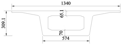
1-1 Section
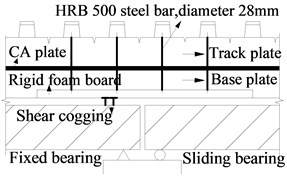
c) Schematic sketch of track structure
Table 1Section parameters of elastic beam elements
Sectional area /m2 | Elastic modulus / kN/m2 | Shear modulus / kN/m2 | Torque / kN∙m | Inertia moment 1 / m4 | Inertia moment 2 / m4 | |
Main girder | 9.06 | 3.45×10⁷ | 1.44×10⁷ | 2.26×101 | 1.10×101 | 9.48×101 |
Base plate | 5.61×10⁻¹ | 3.00×10⁷ | 1.25×10⁷ | 6.74×10⁻³ | 1.69×10⁻³ | 4.06×10⁻¹ |
Track plate | 5.10×10⁻¹ | 3.55×10⁷ | 1.48×10⁷ | 6.80×10⁻³ | 1.70×10⁻³ | 2.76×10⁻¹ |
Rail | 7.75×10⁻³ | 2.06×10⁻⁸ | 8.05×10⁶ | 2.00×10⁻⁶ | 3.20×10⁻⁵ | 5.00×10⁻⁶ |
Fig. 2Spatial finite element model of bridge

2.2. Finite element model
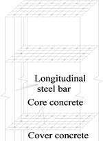
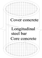
The spatial finite element model of bridges as shown in Fig. 2 is built by using the OpenSEES program. The main girder, base plate, track plate and rail are all simulated by an elastic beam element in OpenSEES, and their section parameters are listed in Table 1. Each unit length for them is 0.65 m, which is the same as the interval between fasteners. Spherical steel bearings, sliding layers, CA layers and fasteners are simulated using a zero length nonlinear connection element as shown in Table 2 and Fig. 3. Friction pendulum bearing (FPB) is simulated using a special Single Friction Pendulum Bearing element as shown in Fig. 4. The pier and pile foundation are simulated by a three-dimensional elastoplastic fiber element. Considering the constraint effect of stirrups, those sections are divided into three parts, including cover concrete, core concrete and reinforcement as shown in Fig. 5. Because the fiber element accounts for material nonlinearity, geometry nonlinearity and bond slip effect of anchoring steel in joint, it is better than other simplified plastic hinge model.
Table 2Parameters of zero length connection elements
Components | Fy / kN | dy / mm |
Sliding layer | 6 | 0.5 |
CA layer | 41.5 | 0.5 |
Fastener | 15 | 2 |
Shear reinforcement | 22.5 | 0.075 |
Lateral block | 453 | 2 |
Fixed spherical steel bearing | 5000 | 2 |
Sliding spherical steel bearing | 470 | 2 |
Fig. 3Constitutive relation of zero length connection element
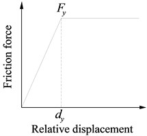
Fig. 4Friction pendulum bearing (FPB)
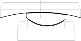
a) Structure of FPB
b) Isolation principle of FPB
c) Hysteresis curve of FPB
Fig. 5Models of pier and pile foundation
a) Pier model
b) Pile model
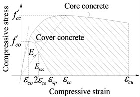
c) Stress-strain diagram of concrete
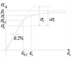
d) Stress-strain diagram of reinforcement
2.3. Parameters of friction pendulum bearing
Fig. 4 shows a type of friction pendulum bearing (FPB) studied in this paper. It can be further divided into three types, including the fixed type, unilateral sliding type and bilateral sliding type. Under common loads, the shear keys on them limit the relative motion between the upper and lower support plates of the fixed bearings and unilateral sliding bearings. However, a large earthquake will cut off those shear keys to cause those bearings to slide like the bilateral sliding bearings. This sliding motion will isolate seismic forces, and the friction force will dissipate earthquake energy. Simultaneously, the girder rises during earthquakes. However, it is almost restored to an original position due to the girder gravity after earthquakes.
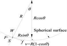
The FPB isolation principle is shown in Fig. 4(b). When the girder relatively moves on the piers, the bearings between them vibrate like a pendulum with a certain period. The period can be changed to an expected value by adjusting the curvature radius R of pendulum.
The relationship between force and displacement of FPB can be obtained from Fig. 4(b). The horizontal displacement u and vertical displacement v are:
The horizontal force F and vertical force W, i.e. the gravity of superstructure, are:
In the equations, f is the friction force, and S is the centripetal force. A new equation can be derived from Eqs. (3) and (4):
The bearing stiffness and vibration period can be approximately obtained as follows:
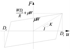
As θ is usually small, cosθ≈1, T=2π√R/g, F=Wsinθ+f=Wu/R+μW, and the bearing hysteretic curve is shown in Fig. 4(c).
In Fig. 4(c), Di is the relatively horizontal displacement of bearing, and μ is the friction coefficient. The effective stiffness according to any Di is shown in Eq. (8):
FPB is simulated using a special Single Friction Pendulum Bearing element as shown in Fig. 3. The main parameters of bearings are shown in Table 3. The structural seismic responses, respectively adopting FPBs with the friction coefficients of 0.02, 0.03, 0.04, 0.05, 0.06, 0.07 and 0.08, will be compared with those using the fixed spherical steel bearings and the sliding spherical steel bearings with the friction coefficient of 0.02.
Table 3Main parameters of bearings
Model name | Friction coefficient on sliding surface | Equivalent radius R /m | |
Left end of beam | Right end of beam | ||
Common | 0.02 | Fixed | Spherical steel bearing |
μ=0.02 | 0.02 | 0.02 | 3.2 |
μ=0.03 | 0.03 | 0.03 | 3.2 |
μ=0.04 | 0.04 | 0.04 | 3.2 |
μ=0.05 | 0.05 | 0.05 | 3.2 |
μ=0.06 | 0.06 | 0.06 | 3.2 |
μ=0.07 | 0.07 | 0.07 | 3.2 |
μ=0.08 | 0.08 | 0.08 | 3.2 |
Fig. 6Ground motion input
3. Ground motions
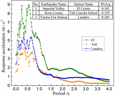
Three earthquake waves, including the ones of the El Centro earthquake (N-S direction), Taft earthquake (N21E direction) and Landers earthquake (N-S direction), are selected from the PEER database, and their spectra are shown in Fig. 6. As to compare them with each other, those ground motions are adjusted to have the same peak ground accelerations (PGA) of 0.2 g, and are inputted into the structural models in the longitudinal direction.
4. Numerical results
4.1. Sliding layer
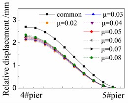
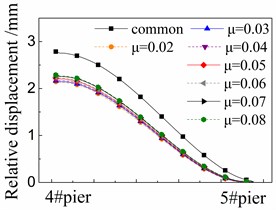
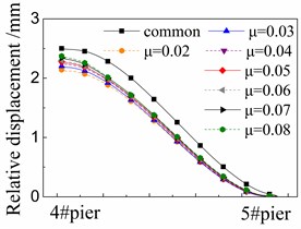
Fig. 7 shows the seismic relative displacement of sliding layer, located between the girder and base plate, of one span supported by the 4# and 5# piers.
Fig. 7Seismic relative displacement of sliding layer
a) Under El
b) Under taft
c) Under landers
The displacement values of sliding layer distribute among 2.0~3.0 mm near the 4# pier, and gradually decrease to 0 mm near the 5# pier, where the shear cogging is set.
At any position, the displacement values of sliding layer in the cases with FPB are much less than those in the common case with the spherical steel bearing. For example, the former is only 76 %-88 % of the latter under the El ground motion in Fig. 7(a). Moreover, the displacement values of sliding layer decrease when the friction coefficient decreases on FPB.
The displacement values of sliding layer are slightly changed under different ground motions by comparing Fig. 7(a), (b) and (c), however, the changing trends are almost the same with each other under different ground motions.
4.2. CA layer
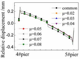
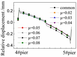
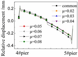
Fig. 8 shows the seismic relative displacement of CA layer, located between the base plate and track plate, of one span supported by the 4# and 5# piers.
The displacement values of CA layer are close to 0mm at the beam ends due to the limitations of shear reinforcement, and in the midspan due to the deformation compatibility. In detail, the displacement values of CA layer at the right end of girder are always larger than those of the left one. The reason is that the shear cogging is set in the sliding layer at the right end of girder and transforms more earthquake energy to the CA layer over there.
The displacement values of CA layer near the girder ends are the largest ones due to the seismic corner responses between beams, and gradually decrease to 0mm in the midspan.
At any position, the displacement values of CA layer in the cases with FPB are much less than those in the common case with the spherical steel bearing. For example, the former is only 58 %-78 % of the latter under the El ground motion in Fig. 8(a). Furthermore, the displacement values of CA layer decrease when the friction coefficient decreases on FPB. However, the decreasing trend is feeble since all of the displacement values of CA layer are very small, being less than 0.3 mm.
The displacement values of CA layer are slightly changed under different ground motions by comparing Fig. 8(a), (b) and (c). However, the changing trends are almost the same with other under different ground motions.
Fig. 8Seismic relative displacement of CA layer
a) Under El
b) Under taft
c) Under landers
4.3. Fastener
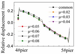
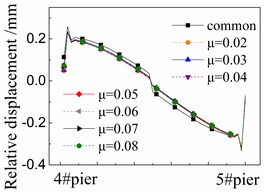
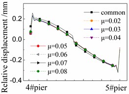
Fig. 9 shows the seismic relative displacement of fasteners, located between the track plate and rails, of one span supported by the 4# and 5# piers. All the displacement values of fasteners are almost the same as those of CA layer as shown in Fig. 8, and the difference between them is less than 0.01 mm.
The displacement values of fasteners are close to 0 mm at the beam ends and in the midspan. In detail, the displacement values of fasteners at the right end of girder are always larger than those of the left one. However, the difference between them is less than that of CA layer due to the isolation protection of the damaged CA layer there.
The displacement values of fasteners near the girder ends are the largest ones, and gradually decrease to 0mm in the midspan.
At any position, the displacement values of fasteners in the cases with FPB are much less than those in the common case with the spherical steel bearings. For example, the former is only 50 %-70 % of the latter under the El ground motion in Figure 9(a). The reduced friction coefficients on FPB further decrease the displacement values of fasteners.
In addition, different ground motions change the displacement values of fasteners by comparing Fig. 9(a), (b) and (c).
However, the influence of those parameters above on the displacement values of fasteners is very insignificant. The fasteners and rails are well protected by FPB, sliding layer and CA layer during earthquakes.
Fig. 9Seismic relative displacement of fastener
a) Under El
b) Under taft
c) Under landers
4.4. Bearings
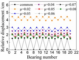
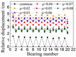
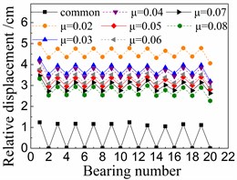
Fig. 10 shows the seismic relative displacement of bearings, including the common spherical steel bearings and FPB with different friction coefficients.
The displacement values of sliding spherical steel bearings are between 1-2 mm, while those of the fixed ones are close to 0 mm. However, the former displacements are still less than any displacements of FPB.
In terms of FPB, the displacement values increase more significantly as the friction coefficients decrease. When the friction coefficient is 0.08 on FPB, the displacement values of FPB are only between 1.5-3 mm. And when the friction coefficient on FPB is reduced to 0.02, the displacement values of FPB reach the range of 4-5 mm.
Fig. 10Seismic relative displacement of bearings
a) Under El
b) Under taft
c) Under landers
4.5. Piers
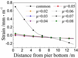
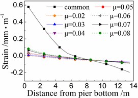
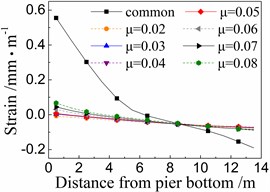
Fig. 11 shows the seismic strain of cover concrete of the 5# pier under the common spherical steel bearings and FPB with different friction coefficients.
When using the common spherical steel bearings, the seismic strains are very large (0.55-0.7 mm/m) for the cover concrete at the bottom of the 5# pier, and decrease along with the pier height. Those strains are much larger than those of pier using FPB.
In terms of the seismic strain of cover concrete of the 5# pier under FPB, the strain values decrease as the friction coefficients on FPB decrease. When the friction coefficient on FPB is 0.08, the strain values of cover concrete at the pier bottom are among 0.05-0.1 mm/m. When the friction coefficient on FPB is reduced to 0.02, those strain values almost decrease to 0 mm/m.
Fig. 11Seismic strain of cover concrete of the 5# pier
a) Under El
b) Under taft
c) Under landers
Fig. 12Seismic strain of core concrete of the 5# pier
a) Under El
b) Under taft
c) Under landers
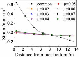
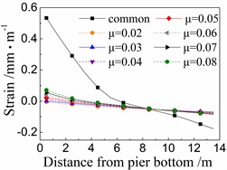
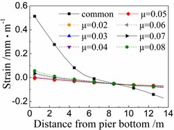
Fig. 12 shows the seismic strain of core concrete near cover concrete of the 5# pier under the common spherical steel bearings and FPB with different friction coefficients. The whole rules are similar to those of the seismic strain of cover concrete as shown in Fig. 11, however, the former is slightly less than the latter.
When using the common spherical steel bearings, the seismic strains are very large (0.5-0.65 mm/m) for the core concrete at the bottom of the 5# pier, and decrease along with the pier height. Those strains are much larger than those of the pier using FPB.
Fig. 13Seismic strain of longitudinal steel bar of the 5# pier
a) Under El
b) Under taft
c) Under landers
In terms of the seismic strain of core concrete of the 5# pier under FPB, the strain values decrease as the friction coefficients on FPB decrease. When the friction coefficient on FPB is 0.08, the strain values of core concrete at the pier bottom are among 0.035-0.075 mm/m. And when the friction coefficient on FPB is reduced to 0.02, those strain values almost decrease to 0 mm/m.
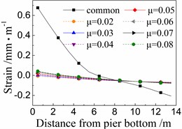
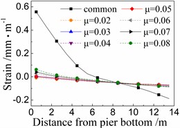
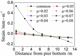
Fig. 13 shows the seismic strains of longitudinal steel bar in the 5# pier under the common spherical steel bearings and FPB with different friction coefficients. The whole rules are similar to those of the seismic strain of concrete as shown in Figs. 11 and 12. Meanwhile, the seismic strains of longitudinal steel bar are between those of cover concrete and core concrete, and are not further discussed here due to space limitations.
5. Multi-layer isolation mechanics
The basic design acceleration 0.1 g of ground motion, according to 10 % probability of exceedance in 50 years for the seismic hazard level, is common for the high-speed railway in China. And the high-grade design acceleration of ground motion can adopt 0.2 g for a higher seismic hazard level with 2 %-5 % probability of exceedance in 50 years. Therefore, it is reasonable to adjust the PGA to be 0.2 g for the three earthquake waves including the ones of the El Centro earthquake (N-S direction), Taft earthquake (N21E direction) and Landers earthquake (N-S direction) in Section 3.
Section 4 shows that the seismic responses subjected to the El Centro earthquake are the largest among those under three ground motions. And thus, the peak response values in a certain position of each component subjected to the El Centro earthquake, as described in Section 4, are drawn in Fig. 14 to display the seismic response distribution and variation in a track-bridge system by using different bearings. Fig. 15 gives the clearer values for some local positions of Fig. 14 by adjusting the coordinate proportion.
Fig. 14Response distribution in a track-bridge system under the El Centro earthquake
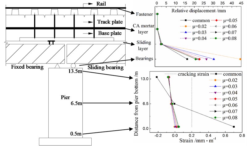
The seismic responses and damage of components near the rail are sensitive to the driving safety of train after earthquakes, and should be little in theory. Figs. 14 and 15 show that the fastener and CA layer are well protected by the multiple isolation layers including the FPB bearing and sliding layer during earthquakes, when compared with the seismic responses using only one sliding layer for isolation in the cases with the common spherical steel bearings. Moreover, the sliding layer is also protected by the FPB bearing during earthquakes.
Any cracks would lead to potential corrosion problems of pier. However, Figure 14 shows that the strain of cover concrete at the bottom of pier exceeds the cracking strain in the cases using the common spherical steel bearings. This strain decreases rapidly and is less than the cracking strain by using the multiple isolation layers, including the FPB bearing and sliding layer, instead of only one sliding layer for seismic isolation.
Based on the above discussions, the multi-layer isolation mechanics, combined by the FPB and sliding layer, should be recommended for seismic design since it protects both the track structure and the pier from seismic damage. And the friction coefficient around 0.05 will be perfect for FPB through comprehensively considering the longitudinal seismic responses of bridge and track structures and the relative displacement of bearings themselves. It leads to a large reserve of safety to resist a stronger earthquake with a much higher hazard level.
Fig. 15Response distribution in local positions of a track-bridge system under the El Centro earthquake
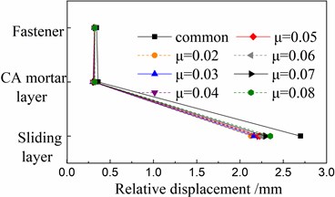
a) Components of track structure
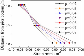
b) Cover concrete of pier
6. Conclusions
1) FPB can effectively protect the bridge and track structures when compared with the common spherical steel bearings under longitudinal earthquakes, but with an allowably large bearing deformation.
2) FPB with a less friction coefficient leads to less responses of the sliding layers and piers but increases the bearing deformation under longitudinal earthquakes. The influence of FPB friction coefficient on the CA layers and fasteners is insignificant. The friction coefficient around 0.05 will be perfect for FPB through considering the longitudinal seismic responses of bridge and track structures.
3) The combination of FPB and CRTS II slab ballastless track is reasonable under longitudinal earthquakes. The rails, fasteners, CA layer and piers are perfectly protected by multi-layer isolation mechanics, induced by the FPB and sliding layer, even under strong earthquakes. It leads to a large reserve of safety to resist a stronger earthquake with a much higher hazard level.
4) The conclusions 1), 2) and 3) have been validated by a series of experiments on different types of FPB and common spherical steel bearings setting between the girder and piers of railway bridges [26, 27]. And several new phenomena have been found. The cutting off of shear keys, changing of friction coefficients with time and space on FPB under spatial earthquakes and other details need further investigation. However, this paper has given a major research area for protecting the track-bridge system against earthquakes based on a numerical analysis.
References
-
He X., Wu T., Zou Y. F., Chen Y. F., Guo H., Yu Z. W. Recent developments of high-speed railway bridges in China. Structure and Infrastructure Engineering, Vol. 13, Issue 2017, 12, p. 1584-1595.
-
Yan B., Dai G. L., Hu N. Recent development of design and construction of short span high-speed railway bridges in China. Engineering Structures, Vol. 100, 2015, p. 707-717.
-
Jiang C. W., Wei B., Wang D. B., Jiang L. Z., He X. H. Seismic vulnerability evaluation of a three-span continuous beam railway bridge. Mathematical Problems in Engineering, 2017, https://doi.org/10.1155/2017/3468076.
-
Shao G. Q., Jiang L. Z. Experimental investigations of the seismic performance of bridge piers with rounded rectangular cross-sections. Earthquakes and Structures, Vol. 7, Issue 25, 2014, p. 463-484.
-
Wei B., Yang T. H., Jiang L. Z., He X. H. Effects of friction-based fixed bearings on the seismic vulnerability of a high-speed railway continuous bridge. Advances in Structural Engineering, 2017, https://doi.org/10.1177/1369433217726894.
-
Wei B., Wang P., He X. H., Jiang L. Z. The impact of the convex friction distribution on the seismic response of a spring-friction isolation system. KSCE Journal of Civil Engineering, 2017, https://doi.org/10.1007/s12205-017-0938-6.
-
Wei B., Wang P., Liu W. A., Yang M. G., Jiang L. Z. The impact of the concave distribution of rolling friction coefficient on the seismic isolation performance of a spring-rolling system. International Journal of Non-Linear Mechanics, Vol. 83, Issue 1, 2016, p. 65-77.
-
Wei B., Wang P., Yang M. G., Jiang L. Z. Seismic response of rolling isolation systems with concave friction distribution. Journal of Earthquake Engineering, Vol. 21, Issue 2, 2017, p. 325-342.
-
Wei B., Zuo C. J., He X. H., Jiang L. Z. Numerical investigation on scaling a pure friction isolation system for civil structures in shaking table model tests. International Journal of Non-Linear Mechanics, Vol. 98, Issue 1, 2018, p. 1-12.
-
Wei B., Wang P., Yang T. H., Dai G. L., Jiang L. Z., Wen Y. Effects of friction variability on isolation performance of rolling-spring systems. Journal of Central South University, Vol. 23, Issue 1, 2016, p. 233-239.
-
Wang S., Hwang J., Chang K., Shiau C., Lin W., Tsai M. Sloped multi-roller isolation devices for seismic protection of equipment and facilities. Earthquake Engineering and Structural Dynamics, Vol. 43, Issue 10, 2014, p. 1443-1461.
-
Chung L. L., Kao P. S., Yang C. Y., Wu L. Y., Chen H. M. Optimal frictional coefficient of structural isolation system. Journal of Vibration and Control, Vol. 53, Issue 3, 2015, p. 388-394.
-
Ortiz N. A., Magluta C., Roitman N. Numerical and experimental studies of a building with roller seismic isolation bearings. Structural Engineering and Mechanics, Vol. 54, Issue 3, 2015, p. 475-489.
-
Xiang N., Li J. Experimental and numerical study on seismic sliding mechanism of laminated-rubber bearings. Engineering Structures, Vol. 141, 2017, p. 159-174.
-
Shen X., Wang X., Ye Q., Ye A. Seismic performance of Transverse Steel Damper seismic system for long span bridges. Engineering Structures, Vol. 141, 2017, p. 14-28.
-
Jara M., Casas J. R. A direct displacement-based method for the seismic design of bridges on bi-linear isolation devices. Engineering Structures, Vol. 28, Issue 6, 2006, p. 869-879.
-
Anderson E. L. Performance-Based Design of Seismically Isolated Bridges. University of California, Berkley, USA, 2003.
-
Wei B., Yang T. H., Jiang L. Z. Influence of friction variability on isolation performance of a rolling-damper isolation system. Journal of Vibroengineering, Vol. 17, Issue 2, 2015, p. 792-801.
-
Wang Y. P., Chung L. L., Liao W. H. Seismic response analysis of bridges isolated with friction pendulum bearings. Earthquake Engineering and Structural Dynamics, Vol. 27, Issue 10, 1998, p. 1069-1093.
-
Kim Y. S., Yun C. B. Seismic response characteristics of bridges using double concave friction pendulum bearings with tri-linear behavior. Engineering Structures, Vol. 29, Issue 11, 2007, p. 3082-3093.
-
Eröz M., DesRoches R. The influence of design parameters on the response of bridges seismically isolated with the friction pendulum system (FPS). Engineering Structures, Vol. 56, 2013, p. 585-599.
-
Eröz M., Desroches R. Bridge seismic response as a function of the Friction Pendulum System (FPS) modeling assumptions. Engineering Structures, Vol. 30, Issue 11, 2008, p. 3204-3212.
-
Castaldo P., Palazzo B., Vecchia P. D. Seismic reliability of base-isolated structures with friction pendulum bearings. Engineering Structures, Vol. 95, 2015, p. 80-93.
-
Jangid R. S. Stochastic response of bridges seismically isolated by friction pendulum system. Journal of Bridge Engineering, Vol. 13, Issue 4, 2008, p. 319-330.
-
Tsopelas P., Constantinou M. C., Kim Y. S., Okamoto S. Experimental study of FPS system in bridge seismic isolation. Earthquake Engineering and Structural Dynamics, Vol. 25, Issue 1, 1996, p. 65-78.
-
Wei B., Jiang L. Z. Experimental Report of New FPB Bearings on the New Railway from Chengdu to Lanzhou. Central South University, Changsha, China, 2017, (in Chinese).
-
Kang X., Jiang L. Z., Bai Y., Caprani C. C. Seismic damage evaluation of high-speed railway bridge components under different intensities of earthquake excitations. Engineering Structures, Vol. 152, Issue 1, 2017, p. 116-128.
Cited by
About this article
This research is jointly supported by the National Natural Science Foundations of China under grant No. 51578549, U1434204, 51778635, 51308549 and 51378504, the Scientific Research and Development Program of China Railway Corporation under SY2016G001, the Natural Science Foundations of Hunan Province under grant No. 2015JJ3159, the Experimental Foundations of Seismic Comprehensive Test for Railway Bridge Piers in High Intensity Earthquake Area from Chengdu to Lanzhou, and Experimental Foundations of Shock Absorber and Block on Railway Bridges. The above support is greatly appreciated.
In this paper, Zhiwu Yu reviewed the investigation history of seismic isolation methods and put forward the research framework. Haiyan Li built the FEM model of track-bridge system and calculated the structural seismic responses. Biao Wei analyzed and discussed the structural seismic responses and put forward the definition of multi-layer isolation mechanics. Lizhong Jiang provided the ground motions and improved the English language. Jianfeng Mao drew some figures and provided the structural parameters of track-bridge system.

