Abstract
Power extraction from ambient vibrations is currently needed or the technology, and the amount of energy in ambient vibration is low and is sufficient to operate small devices. In the present article a methodology is proposed to extract the maximum amount of power from these sources. This paper includes the method to increase the output voltage in a vibration energy harvesting device. The vibration amplitude depends on stiffness, mass damping, vibrating source amplitude and frequency. Various methods are developed to increase the voltage output from these devices. An induced voltage can be further increased by changing the initial relative position between the magnet and coil. Magnetic flux density is found to be maximum in the vicinity of the coil. When the top magnet side matches with the coil centre, then the induced voltage is found to be maximum as compared to other relative positions between the coil and magnet. The multi-magnet arrangement has been used to enhance the total output of the device by keeping appropriate relative position of magnet with respect to the coil. A theoretical and experiment investigation is conducted on these methods, and a theoretical simulation is carried out using a FEA tool, and the experimental results closely match with the theoretical results. Four magnet coils have been considered in this study which gives the maximum output of 1.937 V, 1.426 V, 2.01 V and 2.27 V at 14 Hz frequency. With the help of a multi-magnet arrangement, maximum 7.64 V and 11.44 mW is reached. It observed that the multi-magnet arrangement is the best and gives the maximum voltage output as compared to other methods.
1. Introduction
All over the world, day by day the energy becomes more expensive and is found to be rarer and rarer. Hence, it is necessary to harvest the energy. In the past years, a wide variety of materials, such as piezoelectric materials [1-3] and dielectric elastomers [4-6], and a broad range of mechanisms, such as electrostatic [7-9] and electromagnetic generators [10-12], were developed. These techniques or materials enable to exploit energy sources which are not usually applied, then to increase the energy efficiency. Concerned to vehicles, it is possible to extract, for example, repetitive movements of car dampers [13-15]. These movements are due to roads irregularities and driving conditions such as acceleration, braking and curves.
When an external force is exerted upon the system, the produced oscillations are called as forced vibration. The system vibrates at the excitation frequency due to oscillatory excitation. At an instant when the excitation frequency coincides with the natural system frequency, dangerously large oscillations may occur, and this condition is said to be resonance.
General energy harvesting devices taken into consideration are mechanical motion rectifiers [16-19], piezoelectric shock absorbers [20, 21] and electromagnetic regenerative shock absorbers [15, 22-24].
Vibration energy harvesting (VEH) is an important source of energy specifically where the conventional energy source is not available. Alkaline batteries may be used for portable devices but if the power requirement is continuous, it leads to its frequent changes. Also, alkaline batteries’ recycling becomes difficult [25] and pollutes the environment. The VEH devices have one major limitation of low efficiency resulting in the low-voltage generation at a low frequency [26, 27]. Different devices and sensors require a higher voltage power source [28] which the VEH device does not provide. Also, the produced voltage is of the AC type which may require to be converted to DC voltage. This AC/DC conversion has also low efficiency.
Depending on the excitation amplitude, frequency and spring stiffness, the amplitude of vibration varies [29]. But the initial position of magnet affects the output voltage generated with the same amplitude of vibration [30, 31]. In the first part of this article, a simulated and experimental analysis of different relative positions of magnet and coil is studied.
To store the harvested power in chemical batteries, it requires having a higher voltage [32, 33]. The second part of this paper covers the use of multi-magnet arrangement to enhance a voltage generated in the VEH device.
2. Theory
The vibration energy harvesting device consists of a mass (magnet), spring and a damper system. In response to an external vibration source, the mass vibrates. The relative amplitude of vibration [34, 35] is given by:
This vibrating magnet and coil fixed to the device structure will have a relative displacement, which produces EMF in the coil whose magnitude obeys the Faraday’s law.
Fig. 1Schematic diagram for vibrational energy harvesting device

The Faraday’s law of electromagnetic induction states that, when an electric conductor is moved through a magnetic field, a potential difference is induced between the conductor ends. He proposed the principle that the electromotive force, induced in a conductor, is proportional to the time rate of change of the magnetic flux of that conductor. The magnetic flux B from the magnet assembly radially penetrates each coil section over the magnet height. Therefore, the EMF, V (volt) generated by the conductor of length, L in the form of coils with ‘n‘ turns, moving in the constant magnetic field, B, at the constant velocity, v according to the above law:
Voltage induced in the system is given by:
here ˙z is the instantaneous velocity. The VEH device energy is the energy consumed for the electromagnetic damping.
Instantaneous power generated is given by Eq. (4):
where ce is the electrical induced damping coefficient.
Instantaneous magnitude of generated power Pin is given by Eq. (5):
At resonance, power is maximum and is given by Eq. (6):
where RL is the load resistance, and RC is the coil resistance
Therefore, it can be concluded that power, P, is directly proportional to the square of flux density, B. A double increase in the flux density results in a quadratic power increase. So, the energy harvester is designed to have a higher magnetic flux by using permanent magnets and using good electric conductors [8, 36-38]. Fig. 1 shows the schematic diagram for the vibrational energy harvesting device.
Researchers have developed different methods to extract the maximum energy from vibration at a low frequency. Rao [39] and Bower [40] constructed a low-frequency, non-resonating arrangement in which a ball magnet moves freely in a spherical cavity, and a copper coil is wrapped on the cavity. Lee and Chung [41] developed a harvester which consists of a thin flame resister planer spring, copper coil and a NdFeB permanent magnet which resonates at 8 Hz. Jung and Yun [42] designed a harvester which consists of a proof mass attached to the bulk slender bridge, and of a proof mass cantilever beam attached to it. Lee [43] converted the low frequency resonating mode to the high frequency one with a micro slider and cantilever biomorph. Kulal and Najafi [44] converted low frequency (25 Hz) to high frequency (11.4 kHz) through an electro-mechanical up-converter. Gulchev [45] also used the parametric frequency up-generator to convert low frequency vibration to high frequency. Pillatsch [46] used an inertial device which combines the rotating proof mass and plucking of piezoelectric beam through magnetic coupling.
Some other methods are also developed for low frequency vibration energy harvesting by different researchers. Naruse [7] developed a micro power generator which consists of a stripe masked electret operating at 2 Hz frequency. Jo and Kim [47] proposed to harvest energy from human body motions. It consists of a magnetic spring and inductive components. The device works within the frequency range of 1 to 15 Hz. Zhang [48] used laminated plates which are magnetically forced vibrations with piezomagnetic and piezoelectric layers. Xianzhi Dai [49] used electromagnetic transducers of multiple laminates to convert ambient mechanical vibration to electrical energy. Jin Yang [50] has improved the performance of the energy harvesting device by using one fixed magnet and one movable magnet mounted on the cantilever beam. This nonlinear rod motion leads to a double power peak with the increased frequency bandwidth. Jin Yang [51] designed an energy harvester which can operate in two-directional motions using a magneto-electric transducer. Due to the magnetic interaction between the ME transducer and magnets, nonlinear rod oscillations increased the device bandwidth.
Table 1Summary of VEH devices developed and their output
Sr. No. | Research group | Frequency (Hz) | Voltage (mV) | Power (µW) |
1 | Bowers et al. [40] | 15 | 700 | |
2 | Yuan Rao et al. [39] | 20 | 1.2×10³ | 45 |
3 | Lee et al. [43] | 8 | 720 | 65.33 |
4 | Jung et al. [44] | 30 | 27.1×10³ | 131 |
5 | Kulah et al. [46] | 10 | 150 | 2.5 |
6 | Galchev et al. [7] | 2 | – | 57 |
7 | Pillatsch et al. [47] | 2 | 10 | 43 |
8 | Jo et al. [49] | 8 | 430 | |
9 | Jin Yang et al. [53] | 4.4 | 590 | |
10 | Proposed device | 14 | 8.1 | 12.86×10³ |
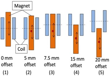
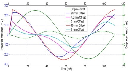
Waveform of induced voltage depends on the relative position of magnet and coil. Fig. 2(a) shows different relative position of magnet and coil, and Fig. 2(b) shows a simulated voltage waveform generated for the amplitude of 5 mm at 9 Hz.
Fig. 2Induced voltage waveform generated: a) different relative position of magnet and coil; b) its simulated induced waveform
a)
b)
From Fig. 2(b) it is clear that the induced waveform depends on the initial relative position of magnet and coil. The maximum voltage is induced in the system when the offset is 15 mm as shown in Fig. 2(a). From Fig. 2(b) it is clear that for inducing the maximum voltage, the top side of the magnet should match with the coil center line. This is mainly due to the magnetic flux distribution and direction of flux lines. At the S and N poles, the flux density is maximum, and the flux lines are normal relative to the coil. So, when the S or N pole is in the coil centre, the contacting flux density is maximum so the induced EMF is maximum too. Also for one cycle vibration motion of magnet, there will be one sinusoidal form of the output voltage.
To increase the output voltage, a number of magnet and coil pairs can be used. When the ends of all coils are connected in series, the total output waveform is the summation of instantaneous voltages in all coils. To ensure the total voltage developed to be maximum, the induced waveform should be same for all coils. This can be achieved by keeping the same relative position of all magnets [3, 52, 53]. When the top of magnets coincides with the coil centre, the induced voltage is maximum for the same amplitude and frequency of magnet.
3. Construction of vibrational energy harvesting device
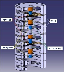
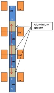
This device consists of four magnets and four coils shown in Fig. 3(b). All the magnets are connected rigidly. Aluminum spacers are chosen and used to keep the required spacing between the magnets as this material is non-magnetic in nature. This device has a unique resonant frequency due to the presence of rigid connection between all the magnets. If the relative positions of magnet and coil are different, the developed waveform is different. To get the maximum output voltage, the top of magnet coincides with the centre of coil. To have a uniform waveform, all the relative positions of magnets and coils are the same.
The maximum amplitude is obtained at the natural frequency of device. The generated waveform depends on the initial relative position of magnet with coil. The same waveform results in the summation of instantaneous voltages induced in each coil. To get the maximum voltage output, all the magnets in the static condition are arranged such that the top magnet coincides with the centre of coil.
Fig. 3VEH device construction: a) pro-e model; b) coil and magnet relative position
a)
b)
By using a vibration exciter, we can give excitation of the known amplitude (0-6 mm) and frequency (0-50 Hz). The VEH device is excited by the frequency of 0 to 16 Hz, and the 3 mm displacement is given to the magnet. In the vibration energy harvesting device, the 3 mm displacement is given to the magnet within the frequency spectrum of 0 to 16 Hz to generate the energy in the form of voltage.
4. FEA analysis
4.1. Modal analysis
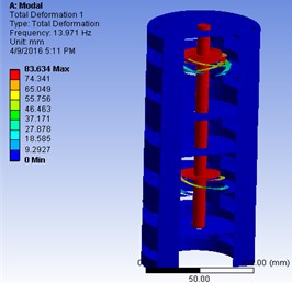
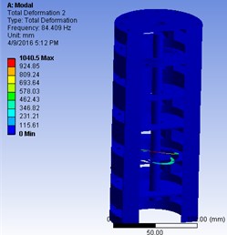
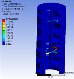
The Modal Analysis is performed in ANSYS Workbench R14.5, to find out the natural frequency values and its corresponding mode shapes. Fig. 4 shows the first three natural frequencies by a modal analysis.
The Modal Analysis shows that the first mode occurs at 13.97 Hz, and the mode shape shows that the displacement is along the longitudinal direction (i.e. Z direction). This mode is important because the displacement in this mode is responsible for the EMF generation. The second and third modes occur at 84.409 Hz and 84.904 Hz correspondingly. The mode shape shows the direction of these modes is along rotational X and Y directions respectively. In the second and third modes, the magnet is almost stagnant but the spring vibrates, what shows that the EMF induced is almost negligible. Hence, these modes are not considered during the experiment.
Mesh parameters are also taken into account by using the Tetrahedron mesh and Hexahedron mesh elements. In the Tetrahedron element mesh, the average mesh quality of 86 % was used (that seems to be good as per industry standards). In the Hexahedron element, the results were almost the same as tetrahedron elements. In addition to the Element quality, the Jacobian ratio was also taken into consideration to avoid the negative Jacobian ratio in elements. The first modal frequency is the same as obtained during the experiment.
Fig. 4Modal analysis of device: a) first mode; b) second mode; c) third mode
a)
b)
c)
4.2. Electromagnet energy generation simulation
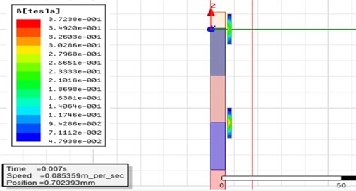
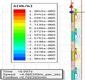
The VEH device arrangement is simulated in the ANSOFT Maxwell software which is set to 2D DESIGN. The model is cylindrical about the Z-axis. The solution type was selected as ‘transient type’. The model was drawn with pre-selected values. Different drawn components were named accordingly like a magnet, coil, band, region, etc. The material selected for the magnet is NdFeB 35 (neodymium) and, for the coil, it is copper. The coordinates for the geometry are set in the option ‘create rectangle’. An air gap of 1 mm is set between the coil and the magnet. A rectangle called as ‘band’ was drawn around the magnets with greater dimensions. A ‘region’ with a percentage offset was created. The magnets are assigned for motion with positive and negative translation limits. The coil was assigned as a winding with the set parameters like a number of turns, reluctance, inductance, voltage, etc. Lengthwise mesh operations were selected for the setup in the ‘analysis’ section with linear steps. Figs. 5(a) and (b) show the magnetic flux density and flux lines distribution. The plots of induced voltage, flux linkage, velocity versus time were obtained in the ‘results’ section by selecting the type of plot as the X-Y plot. The solutions were obtained.
Fig. 5Maxwell simulation of VEH device for: a) magnetic flux density, b) flux lines of magnet 1 and 2
a)
b)
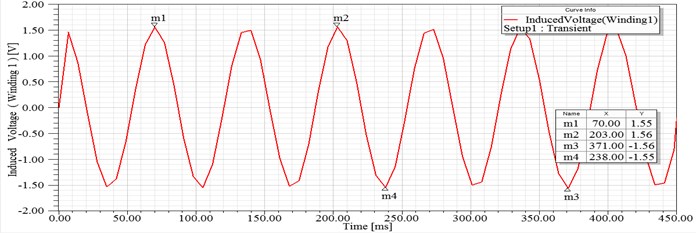
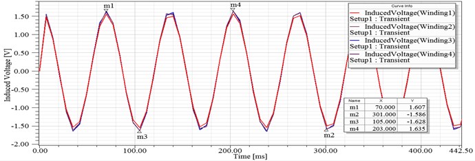
Fig. 6(a) and (b) shows the simulated EMF generated in coils. As a representative EMF generated in two coils is shown, the actual output is obtained from four coils. Fig. 6(c) shows EMF generated in four coils on a common time scale which shows that EMF in all coils gives the peak voltage at the same time. This allows connecting the output of all coils in series to get the enhanced output voltage.
Fig. 6FEA Simulated EMF generated in coils
a)XY plot 1

b)XY plot 2
c)XY plot 7
5. Experimental set
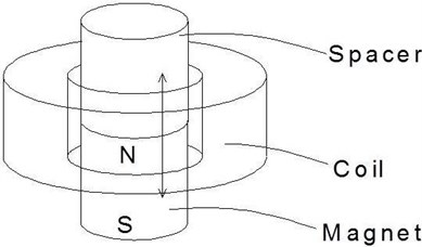
Experimental set consists of a multi-magnet electromagnetic harvesting device with a set of four coils and magnets. This device consists of an outer frame made up of aluminum (non-magnetic material), 3 beryllium copper flexural springs, 4 permanent magnets and 4 copper wound coils. Fig. 7 shows the architecture of Magnet in-line coil, it carries a coil, magnet and spacer. The springs are spiral-shaped with 4 numbers of starts. It is suspended between two spacers with the help of bolted joints. The outer frame is the main mass system made up of aluminum with a hollow body. Holes are provided on the outer periphery of the frame to accommodate the bolts.
The coils are made up of a copper wiring wound on a plastic bobbin. The number of turns is 2679 with the gauge diameter of 47 µm. The resistance and inductance of copper wiring is 1342 Ω and 67.91 mH respectively. The natural frequency of system is 14 Hz. Neodymium Iron Boron cylindrical magnets are used to serve the purpose of permanent magnets because they exhibit the highest magnetic properties among all the magnetic materials. When the magnets oscillate towards the coils, according to the Faraday’s law of electromagnetic induction, voltage will be induced in these coils.
Fig. 7Magnet in-line coil architecture
The experimental set (Fig. 8) also contains a vibration exciter which is used to excite the harvesting device and has the capacity to be excited at the known amplitude (0 to ±6 mm) and known frequency within range of 0 to 50 Hz. The exciter is actuated by a signal controller from a dSPACE DS1104 R&D controller through a Linear Current Amplifier (LCAM). The LCAM amplifies low-voltage signals from the DAC which are insufficient for driving the exciter. The energy harvesting device assembly is mounted on the exciter so that, due to excitation, the desired amplitude and frequency can be given. Due to a relative displacement between coil and magnet, the EMF is induced. These induced EMF signals are given to a suitable circuitry and feedback signal given to the data acquisition system (dSPACE) through an ADC port. Also, a relative displacement of magnet and coil can be measured and give feedback to the acquisition system (dSPACE) through an ADC port.
Fig. 8Experimental set
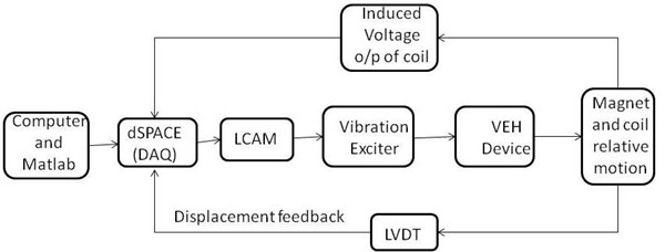
a) Block diagram
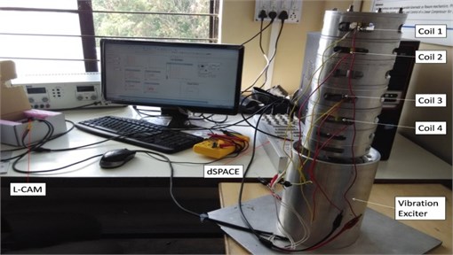
b) Actual setup
6. Result and discussion
Experiments are conducted within the frequency range of 1-16 Hz by using a vibration energy harvesting device to get the energy in the form of voltage. Through an experimental study, it is observed that, as frequency increases, then the induced voltage in the coil also increases, and at 14 Hz frequency, the induced voltage is found to be the highest. The induced voltages in the coils i.e. from coil 1 to coil 4 are 1.937 V, 1.426 V, 2.01 V and 2.27 V respectively across 5.1 kΩ. The magnitude of the induced voltages gets reduced at higher frequencies. From Fig. 9, it is found that, even though the magnet displacement of disturbance, it is controlled but still there is a change in the input frequency. If the output waveforms of all four coils are superimposed on the same real time scale, it is observed that the induced voltage reaches to its maximum and zero value simultaneously. The series connection of all four coils leads to giving a high voltage in the system. This high voltage is approximately the arithmetic summation of individual voltages.
Fig. 9Graphical user interface of data acquisition system
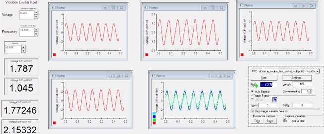
Fig. 10 shows the voltage induced in each coil within the frequency spectrum of 11 to 16 Hz. It also shows the total voltage in the system which is obtained by the theoretical and experimental methods. The series connection is considered for the magnets to obtain the total voltage obtained in the system. Fig. 10 shows a theoretical summation of the total voltage, and the actual total voltage generated is almost the same. This clearly establishes that, if the waveform of induced voltage is the same for all coils, its addition is possible.
Fig. 10Induced voltage for individual coils and total voltage at different frequencies
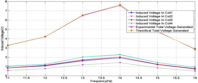
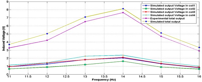
Fig. 11 shows a simulated induced voltage in each coil, the simulated total voltage and actual total voltage in the system at different frequencies. It is also found that the actual total voltage is slightly moved towards the lower side than the simulated voltage in the system due to the existence of flux leakage and air gap.
Fig. 11Simulated voltage for individual coils and actual total voltage at different frequencies
7. Conclusions
From this study, it is observed that the output of vibration energy harvesting device depends on the relative displacement of the magnet with respect to the coil, flux density of the magnet and also on the frequency of vibrating cycle. The maximum voltage is induced in the system when the top side of magnet comes in the vicinity of the coil centre. The concept of Multi-magnet arrangement in the system enhances the output voltage of the vibration energy harvesting device. By using a multi-magnet arrangement with four magnets up to 7.64 V, and 11.44 mW output is reached.
References
-
Elfrink R. Vibration energy harvesting with aluminum nitride based piezoelectric devices. Journal of Micromechanics and Microengineering, Vol. 19, Issue 9, 2009, p. 094005.
-
Galchev T., Aktakka E. E., Najafi K. A Piezoelectric parametric frequency increased generator for harvesting low-frequency vibrations. Journal of Microelectromechanical Systems, Vol. 21, Issue 6, 2012, p. 1311-1320.
-
Liu H., Tay C. J., Quan C., Kobayashi T., Lee C. Piezoelectric MEMS energy harvester for low-frequency vibrations with wideband operation range and steadily increased output power. Journal of Microelectromechanical Systems, Vol. 20, Issue 5, 2011, p. 1131-1142.
-
Koh S. J. A., Keplinger C., Kaltseis R., Foo C., Baumgartner R., Bauer S., Suo Z. High-performance electromechanical transduction using laterally-constrained dielectric elastomers. Part I: Actuation processes. Journal of the Mechanics and Physics of Solids, Vol. 105, 2017, p. 81-94.
-
Wang K., Ouyang G., Chen X., Jakobsen H. Engineering electroactive dielectric elastomers for miniature electromechanical transducers. Polymer Reviews, Vol. 57, Issue 3, 2017, p. 369-396.
-
Invernizzi F., Dulio S., Patrini M., Guizzetti G., Mustarelli P. Energy harvesting from human motion: materials and techniques. Chemical Society Reviews, Vol. 45, Issue 20, 2016, p. 5455-5473.
-
Naruse Y., Matsubara N., Mabuchi K., Izumi M., Suzuki S. Electrostatic micro power generation from low-frequency vibration such as human motion. Journal of Micromechanics and Microengineering, Vol. 19, Issue 9, 2009, p. 94002.
-
Peano F., Tambosso T. Design and optimization of MEMS electret-based capacitive energy scavenger. Journal of Microelectromechanical Systems, Vol. 14, Issue 3, 2005, p. 429-435.
-
Lo H., Tai Y. Parylene-based electret power generators. Journal of Micromechanics and Microengineering, Vol. 18, Issue 10, 2008, p. 104006.
-
Saadatnia Z., Asadi E., Askari H., Zu J., Esmailzadeh E. Modeling and performance analysis of duck‐shaped triboelectric and electromagnetic generators for water wave energy harvesting. International Journal of Energy Research, 2017, https://doi.org/10.1002/er.3811.
-
Fan F. R., Tang W., Yao Y., Luo J., Zhang C. Complementary power output characteristics of electromagnetic generators and triboelectric generators. Nanotechnology, Vol. 25, Issue 13, 2014, p. 135402.
-
Wurz M. C., Kleyman G., Twiefel J. Highly-integrated energy harvesting device for rotational applications utilizing quasi-static piezoelectric and electromagnetic generators. Proceedings of SPIE, 2013.
-
Wei C., Taghavifar H. A Novel approach to energy harvesting from vehicle suspension system: half-vehicle model. Energy, Vol. 134, 2017, p. 279-288.
-
Xie X. D., Wang Q. Energy harvesting from vehicle suspension system. Energy, Vol. 86, 2015, p. 385-392.
-
Li Z., Zuo L., Luhrs G., Lin L., Qin Y. Electromagnetic energy-harvesting shock absorbers: design, modeling, and road tests. IEEE Transactions on Vehicular Technology, Vol. 62, Issue 3, 2013, p. 1065-1074.
-
Li Z., Zuo L., Kuang J., Luhrs G. Energy-harvesting shock absorber with a mechanical motion rectifier. Smart Materials and Structures, Vol. 22, Issue 2, 2013, p. 25008.
-
Liu Y., Xu L., Zuo L. Design, modeling, lab and field tests of a mechanical-motion-rectifier-based energy harvester using a ball-screw mechanism. IEEE/ASME Transactions on Mechatronics, Vol. 22, Issue 5, 2017, p. 1933-1943.
-
Liang, Wu Y., Zuo L. Vibration energy harvesting system with mechanical motion rectifier. Dynamic Systems and Control Conference, American Society of Mechanical Engineers, 2015.
-
Liang C., Ai J., Zuo L. Design, fabrication, simulation and testing of an ocean wave energy converter with mechanical motion rectifier. Ocean Engineering, Vol. 136, 2017, p. 190-200.
-
Lee H., Jang H., Park J., Jeong S., Park T., Choi S. Design of a piezoelectric energy-harvesting shock absorber system for a vehicle. Integrated Ferroelectrics, Vol. 141, Issue 1, 2013, p. 32-44.
-
Radeef Zainab, Chong Wen Tong, Ong Zhi Chao, Khoo Shin Yee Energy harvesting based on a novel piezoelectric 0.7 PbZn0. 3Ti0. 7O3-0.3 Na2TiO3 Nanogenerator. Energies, Vol. 10, Issue 5, 2017, p. 646.
-
Li P. Buck-boost converter for simultaneous semi-active vibration control and energy harvesting for electromagnetic regenerative shock absorber. Proceeding SPIE, Active and Passive Smart Structures and Integrated Systems, 2014.
-
Zhang Z., Zhang S., Chen W., Wang C. High-efficiency energy regenerative shock absorber using super capacitors for renewable energy applications in range extended electric vehicle. Applied Energy, Vol. 178, 2016, p. 177-188.
-
Demetgul M., Guney I. Design of the hybrid regenerative shock absorber and energy harvesting from linear movement. Journal of Clean Energy Technologies, Vol. 5, Issue 1, 2017, p. 81-84.
-
Prengaman R. D., Mirza A. H. Recycling concepts for lead-acid batteries. Lead-Acid Batteries for Future Automobiles, 2017, p. 575-598.
-
Lee B., Chung G. Low-frequency driven energy harvester with multi-pole magnetic structure. Journal of Mechanical Science and Technology, Vol. 29, Issue 2, 2015, p. 441-446.
-
Knight C., Davidson J., Behrens S. Energy options for wireless sensor nodes. Sensors, Vol. 8, Issue 12, 2008, p. 8037-8066.
-
Kim H. S., Kim J. H., Kim J. Review of piezoelectric energy harvesting based on vibration. International journal of precision engineering and manufacturing, Vol. 12, Issue 6, 2011, p. 1129-1141.
-
Williams C. B., Yates R. B. Analysis of a micro-electric generator for microsystems. Sensors and Actuators A: Physical, Vol. 52, Issue 1, 1996, p. 8-11.
-
Stephen N. G. On Energy harvesting from ambient vibration. Journal of Sound Vibration, Vol. 293, Issue 1, 2006, p. 409-425.
-
El Hami M., Glynne Jones P., White N. M., Hill M. Design and fabrication of a new vibration-based electromechanical power generator. Sensors and Actuators A: Physical, Vol. 92, 2001, p. 335-342.
-
Matiko J. W., Grabham N. J., Beeby S. P., Tudor M. J. Review of the application of energy harvesting in buildings. Measurement Science and Technology, Vol. 25, Issue 1, 2014, p. 12002-25.
-
Mitcheson P. D., Yeatman E. M., Rao G. K., Holmes A. S., Green T. C. Energy harvesting from human and machine motion for wireless electronic devices. Proceedings of the IEEE, Vol. 96, Issue 9, 2008, p. 1457-1486.
-
Priya Shashank, Daniel Inman J. Energy Harvesting Technologies. Springer, New York, 2009, p. 129-161.
-
Kamierski T. J., Beeby S. P. Energy Harvesting Systems: Principles, Modeling and Applications. Springer, 2010, p. 77.
-
Beeby S. P., Tudor M. J., White N. M. Energy harvesting vibration sources for microsystems applications. Measurement Science and Technology, Vol. 17, Issue 12, 2006, p. 175-195.
-
Renno J. M., Daqaq M. F., Inman D. J. On the Optimal energy harvesting from a vibration source. Journal of Sound and Vibration, Vol. 320, Issue 12, 2009, p. 386-405.
-
Dutoit N. E., Wardle B. L. Experimental verification of models for microfabricated piezoelectric vibration energy harvesters. The American Institute of Aeronautics and Astronautics Journal, Vol. 45, Issue 5, 2007, p. 1126-1137.
-
Cheng Yuan Shuo, Arnold David P. An energy harvesting system for passively generating power from human activities. Journal of Micromechanics and Microengineering, Vol. 23, Issue 11, 2013, p. 114012.
-
Bowers Benjamin J., David Arnold P. Spherical, rolling magnet generators for passive energy harvesting from human motion. Journal of Micromechanics and Microengineering, Vol. 19, Issues 9, 2009, p. 94008.
-
Lee Byung Chul, Chung Gwiy Sang Design and fabrication of low frequency driven energy harvester using electromagnetic conversion. Transactions on Electrical and Electronic Materials, Vol. 14, Issue 3, 2013, p. 143-147.
-
Jung Seok Min, Yun Kwang Seok Energy-harvesting device with mechanical frequency-up conversion mechanism for increased power efficiency and wideband operation. Applied Physics Letter, Vol. 96, Issue 11, 2010, p. 111906.
-
Lee D. G., Carman G. P., Murphy D., Schulenburg C. Novel micro vibration energy harvesting device using frequency up conversion. Proceedings of 14th International Conference on Solid-State Sensors, Actuators and Microsystems, 2007, p. 871-874.
-
Kulah Haluk, Khalil Najafi An electromagnetic micro power generator for low-frequency environmental vibrations. 17th IEEE International Conference on Micro Electro Mechanical Systems, 2004, p.237-240.
-
Galchev T. V., Mccullagh J., Peterson R. L., Najafi K. Harvesting traffic-induced vibrations for structural health monitoring of bridges. Journal of Micromechanics and Microengineering, Vol. 21, Issues 10-2011, 104005, p. 1-13.
-
Pit Pillatsch, Yeatman Eric M., Holmes Andrew S. A piezoelectric frequency up-converting energy harvester with rotating proof mass for human body applications. Sensors and Actuators A: Physical, Vol. 206, 2014, p. 178-185.
-
Jo S. E., Kim M. S., Kim Y. J. Electromagnetic human vibration energy harvester comprising planar coils. Electronics Letters, Vol. 48, Issue 14, 2012, p. 874-875.
-
Moss S., Barry A., Powlesland I., Galea S., Carman G. P. A Low profile vibro-impacting energy harvester with symmetrical stops. Applied Physics Letters, Vol. 97, Issues 23, 2010, p, 234101.
-
Dai Xianzhi, Yumei Wen, Ping Li, Jin Yang, Ming Li Energy harvesting from mechanical vibrations using multiple magnetostrictive/piezoelectric composite transducers. Sensors and Actuators A: Physical, Vol. 166, Issue 1, 2011, p. 94-101.
-
Yang Jin, Yumei Wen, Ping Li, Xihai Yue, Qiangmo Yu, Xiaoling Bai A two-dimensional broadband vibration energy harvester using magneto-electric transducer. Applied Physics Letters, Vol. 103, Issues 24-2013, 243903, p. 1-5.
-
Yang Jin, Yumei Wen, Ping Li, Xihai Yue, Qiangmo Yu, Xiaoling Bai Design and analysis of a 2D broadband vibration energy harvester for wireless sensors. Sensors and Actuators A: Physical, Vol. 205, 2014, p. 47-52.
-
Beeby S. P., Tudor M. J., Torah R. N., Roberts S., O’donnell T., Roy S. Experimental comparison of macro and micro scale electromagnetic vibration powered generators. Microsystem Technologies, Vol. 13, Issues 11-12, 2007, p. 1647-1653.
-
Pedchenko Alexander V., Bryn Pitt E., Eric Barth J. Analytical tools for investigating stability and power generation of electromagnetic vibration energy harvesters. IEEE/ASME Transactions on Mechatronics, Vol. 21, Issue 2, 2016, p. 717-726.
-
ANSYS Release 12.1, ANSYS Inc, 2009.
-
ANSYS Element Manuals, ANSYS Inc.
-
ANSOFT MAXWELL V15, 2010.
