Abstract
In this paper, we address the problem of altitude and velocity controllers design for variable-sweep aircraft with model uncertainties. The object is to maintain altitude and velocity during the wing transition process where mass distribution and aerodynamic parameters change significantly. Based on the functional decomposition, the longitudinal dynamics of the aircraft can be divided into altitude subsystem in non-affine pure feedback form and velocity subsystem. And then nonlinear robust adaptive NN velocity controller and altitude controller are designed with backstepping method to relax the prior requirements of aerodynamic parameters accuracy in linear LPV controller design. The method of filtered signal is used to circumvent the algebraic loop problem caused by the dynamics of non-affine pure feedback form. Dynamic surface control (DSC) and minimal learning parameters (MLP) techniques are employed to solve the problems of ‘explosion of complexity’ in the back-stepping method and the online updated parameters being too much. The robust terms have been introduced to eliminate the influences of approximation errors. According to the Lyapunov-LaSalle invariant set theorem, the semi-global boundedness and convergence of all the signals of the closed-loop system are proved. Simulation results are presented to illustrate the control algorithm with good performance.
1. Introduction
The morphing and bio-inspired UAV designs has attracted extensive focus because of the ability to optimize flight in different conditions via altering shape [1], possess the remarkable performance, e.g. flight in multiple mission types and extreme maneuver performance, of which is not possible for a traditional fixed-wing aircraft [2, 3]. However, due to the significant changes in mass distribution and aerodynamic parameters while altering shape, an uncertain, time-varying and complicated nonlinear dynamic model is posed which makes a crucial importance in the transient dynamic characteristics [2-4]. And the characteristics induced by configuration change are of paramount importance in controller design for a morphing aircraft [3]. So, the issue of controller design for morphing aircraft has been attached more importance by most researchers.
In order to overcome the controller design problem mentioned above, several linear controllers have been designed. In [5], a total of 350 operating points was computed by considering a generic morphing UAV mission profile to generate LPV model, and then a set of inner-loop gains to provide stability whereas the outer-loop LPV controller guarantees global quadratic stability was proposed based on the multiloop topology. Similarly, self-scheduled controller is used based on LPV model in [6] and a smooth switching controller based on linear parameter variable (LPV) model is applied to control morphing aircraft in [7]. In addition, the dynamic equations are converted into switched system in several special points in [8], and then a finite-time boundedness controller is proposed to guarantee steady flight in the morphing process. Furthermore, in [9], the time varying characteristic equation based on the linear time-invariant characteristic equation and the concept of time varying pole are posed to analysis the time-varying dynamic mode of variable-sweep morphing. In [10], an active disturbance rejection controller is proposed based on ADRC without LPV or switched model while the un-modeled dynamics and aerodynamics are observed and compensated as a generalized disturbance in real time.
The controller design methods above are at the basis of linear control with linearized model or linear input variable model. Those linear methods highly depend on the prior accurate aerodynamic parameters, which are strict for morphing controller design. In view of the limitation of a linear controller, nonlinear controllers (e.g. high-order integral chained differentiator control and first-order sliding mode differentiator control) are proposed to overcome the problem in [11, 12], but FPA is limited to sinγ≈γ and the errors of differentiator have not been considered. Therefore, controller for a morphing aircraft with the ability to solve the problem leaded by time-varying uncertain model should be further investigated in details.
To design a nonlinear controller with taking more factors into account, a nonlinear neural network (NN)-based dynamic surface control method is proposed to solve the problem induced by transient dynamic of variable-sweep aircraft with model uncertainties. The control objective is to maintain altitude and velocity during the wing transition process where significant changes in mass distribution, aerodynamic forces and moments occur. On the basis of functional decomposed altitude subsystem and velocity subsystem, a synthesis controller is posted with backstepping method. Compared with traditional flight control coping strict feedback form, the proposed controller is designed based on non-affine pure feedback form. Filtered signal is used to circumvent the algebraic loop problem in altitude controller design to remove the constraint on FPA. In order to overcome the problem of ‘explosion of complexity’ inherent in the conventional back-stepping method, the dynamic surface control(DSC) is utilized to compute the derivatives of virtual control laws and minimal learning parameters(MLP) techniques is employed to regulate the norm of NN’s weight vector to decrease the online updated learning parameters. According to the Lyapunov-LaSalle invariant set theorem, it is proved that the proposed controller is semi-globally uniformly ultimately bounded, of which tracking errors converge to an arbitrary small neighborhood of the origin via choosing designed constants appropriately. Case studies illustrate that the proposed controller shows high morphing flight performance and good feasibility.
2. Aerodynamic parameters
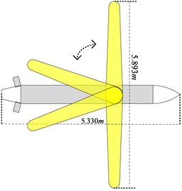
The schematic illustration of the variable-sweep aircraft used for calculating aerodynamic parameters is presented in Fig. 1. The inspiration of the configuration comes from our previous work in [13]. The length of the body is 5.33 m with a maxmum 5.893 m of span and the total mass is assumed to be 200 kg. Datcom is employed for aerodynamics calculation which was developed by the United States Air Force (USAF) for engineering estimation of the aircraft aerodynamics. The program calculates aerodynamics based on experimental results previously which is quite practical to quickly and economically estimate the aerodynamics of a wide variety of aircraft configuration designs [14]. Compared with wind tunnel experiments and computational fluid dynamic (CFD) which are expensive and time consuming, the advent of Datcom has provided variable-sweep aircraft designers with a relatively rapid and economical tool that provides a basic approximation of the aerodynamics of the aircraft.
Fig. 1Schematic illustration of the aircraft
In this paper, Datcom is employed to calculate these derivatives for the aircraft when symmetric planform changes are implemented for that we focus on the longitudinal altitude controller design. To reduce the difficulties in calculating aerodynamic parameters at the basis of guarantee accuracy, the following assumptions are made which are commonly used [1, 15]:
Assumption 1: The outboard wing shape is retentive through an assumed mechanism. That is to say the outboard wing shape is parallel to the axis of the fuselage during wing transition process.
Assumption 2: For simplicity, it is desirable to maintain the quasi-steady approximation; hence, aerodynamic derivatives will be determined for a specific aircraft design.
Assumption 3: The area of the wings is constant in the wing transition process as well as when the sweep angle is 0°.
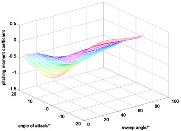
Angle of attack and sweep angle have a great influence in the aerodynamic coefficients. In addition, considering that the Mach and height are changed in a small region for the goal of this paper being to maintain altitude and velocity during variable sweep process, the velocity and altitude are set to be constant during calculating the aerodynamic coefficients. At those basics, the lift coefficient, drag coefficient and pitching moment coefficient calculated by DATCOM are shown in Figs. 2-4.
Fig. 2Lift coefficient
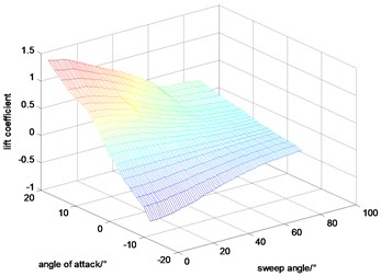
Fig. 3Drag coefficient
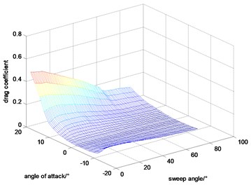
Fig. 4Pitching moment coefficient
3. Dynamic model of the variable-sweep aircraft
In this paper, we concentrate on guaranteeing cruise state to be constant or fluctuate in a small region during the variable sweep aircraft sweeps back. Dynamic model considered here is based on [16]:
where:
4. Altitude controller design
To simplify the controller design process, the velocity controller and the altitude controller are designed separately as in [17, 18]. In this section, a nonlinear robust adaptive NN altitude controller based on backstepping method is proposed for the variable-sweep aircraft. MLP and DSC techniques are used to cope with the problems of ‘explosion of complexity’ as well as the online updated parameters being too much.
Remark 1: In order to transform the altitude system into pure-feedback system, FIkz is regarded as an un-modeled term as in ref. [10].
Remark 2: Considering that the mass of the wing is much smaller than that of the aircraft, it is reasonable to suppose that the moment of inertia Iy is a known constant during the wing transition process for the variable-sweep aircraft.
Define that x1=h, x2=γ, x3=θ, and x4=q, the dynamic model can be expressed in the non-affine pure feedback form, which is expressed as follow:
where:
Lemma 1 [19]: Lyapunov-LaSalle invariant set theory: for a differential dynamic system ˙x=f(x,t) where L:D→R+ is a continuous and differentiable function. Ω={x|L(x)≤p} is a compact set where p∈R+ and Ω⊂D, E={x∈Ω|L(x)=p}. If ∀x∈E, then ˙L(x)≤ 0, we call Ω a invariant set of the system, and get: x(t0)∈Ω⇒x(t)∈Ω, ∀t≥t0.
Lemma 2 [20]: the hyperbolic tangent function is continuous and differentiable, and the following inequalities are established ∀q∈R and ∀c> 0:
Based on backstepping method and DSC, the tracking errors are defined as below:
where e1 is the system tracking error, αi is the virtual control, ei is the tracking errors of virtual controls and αif is the low-pass filtered signal of αi-1.
The control scheme is developed in the framework of back-stepping technique, which contains four-step recursive design procedure.
Step 1: Define e1=x1-yd, and then ˙e1=˙x1-˙yd.
Define the following Lyapunov function Le1=0.5e21, take derivation of Le1 and then:
=e1(W*1ψ(x1,x2f)+ε1+Δf1+d1+x2-˙yd)
≤e1W*1ψ(x1,x2f)+e1δ*1+e1x2-e1˙yd.
In this paper, f1(x1,x2)is an unknown function where neural network can be employed to approximate the function. Filtered signal is used to circumvent the algebraic loop problem in the backstepping method [21]. x2f is a filtered signal of x2 defined as: x2f≡HL(s)x2≈x2. The filtered signal error Δf1 and the minimum NN approximation error ε1 are bounded that |ε1+Δf1+d1|≤δ*1.
In Eq. (8), the following inequality is obtained at the basis of Young inequality:
where is a positive constant needed to be designed.
Take and Eq. (9) into Eq. (8), we can get:
To make the error as small as possible, the virtual control and updating laws are chosen as:
where , , , and is the estimation of .
Augment to obtain:
where and are positive constants.
Take derivation of Eq. (12) along Eq. (11) and consider Lemma 2 to obtain:
Step 2: Define and then .
Define the following Lyapunov function , take derivation of and then:
The filtered signal error and the minimum NN approximation error are bounded that .
In Eq. (12), the following inequality is obtained at the basis of Young inequality:
where is a positive constant needed to be designed.
Take and Eq. (15) into Eq. (14), we can get:
To make the error as small as possible, the virtual control and updating laws are chosen as:
where , , , and is the estimation of .
Augment to obtain:
where and are positive constants.
Take derivation of Eq. (18) along Eq. (17) and considering Lemma 2 to obtain:
Step 3: Define , and then .
Similarly, to make the error as small as possible, the virtual control is chosen as:
where , , are positive constants to be designed.
Define the following Lyapunov function , and take derivation of along Eq. (20), we can get:
Step 4: Define , and then .
According to step 2, define , we can get:
The moment of inertia varies with sweep angle which leads to the uncertainty of . And to overcome the uncertainty, we use to instead of . To make the error as small as possible, the control input and the adaptive law are taken as:
Augment to obtain:
where 5, 10, 5, and are positive constants.
Considering Lemma 2, the time derivative of along Eq. (23) is given:
Theorem 1. Consider the longitudinal altitude system described by Eq. (6), under the assumptions of remark 1, remark 2 and the initial condition , use the control law Eq. (23), filtered signal Eq. (7), virtual control and updating laws in Eq. (11), (17) and (20), then the closed-loop signal are semi-globally bounded, forcing the altitude tracking error to an arbitrary small neighborhood of the origin.
Proof: Consider the following Lyapunov function candidate:
Along Eq. (13), (19), (21) and (25), the time derivative of is obtained:
From Eq. (7), we obtain:
and:
Define:
where is an unknown continuous function.
And then:
Consider that:
From Young inequality, we get:
Take Eq. (28)-(33) into Eq. (27), we get:
Then:
where is positive and , , are positive constant which are designed as below:
And then inequality Eq. (35) satisfies:
Define a compact set and . And display by , and so if , then . is a compact set of . The unknown continuous function is bounded in the compact . From Lemma 1, it is proved that the proposed controller is to be semi-globally uniformly ultimately bounded.
From Eq. (37), it is known that:
when , we get:
The tracking error is bounded by which can be adjusted to arbitrary small of zero. So, the proposed controller can keep the altitude of the variable-sweep aircraft during the wing transition process.
5. Velocity controller design
In this section, a velocity controller is proposed based on NN adaptive control method. We first define:
First, we define , and then:
In this paper, is an unknown function, and an adaptive NN is used to approximate. is the filtered signal of defined as:
where is a Butterworth low-pass filter. The order of the Butterworth LPF utilized is 2 and the corresponding filter parameters of Butterworth filter is cited from [22].
Define the following Lyapunov function where and are positive constants and .
To make the error as small as possible, the control and updating laws are chosen as:
where 666.5 N is the thrust of trim condition for the aircraft with 0 sweep angle.
Proof: Take the derivation of and then:
where:
And similar to aforementioned the stability proof of altitude controller, when , we get:
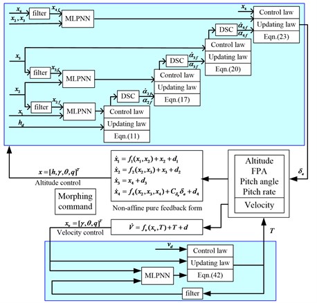
According to Lyapunov-LaSalle invariant set theory, the velocity tracking error is bounded by which can be adjusted to arbitrary small of zero. The control scheme of this paper is shown in Fig. 5.
Fig. 5Controller scheme
6. Simulation
In this section, simulation results will be provided to show the feasibility of the developed methods. As illustrated in Eq. (36) and Eq. (44), the parameters of the proposed controller are selected as: 1, 5, 5, 10, 500. Gains for the adaptive laws are selected as: 1, 10, 10 and the auxiliary parameters are selected as: 1, 0.003. The initial weights of NNs are set to be 0. The variable-sweep aircraft flies at trim condition, of which 2000 m, 100 m/s, 0.92°. The control objects are keeping the altitude and the velocity unchanged during the wing transition process. The simulation scheme is illustrated in Fig. 6.
Fig. 6Simulation Scheme

Fig. 7Sweep forward and then backward
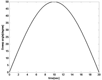
Variation of the sweep angle follows:
0.2 seconds of simulation under the proposed controller with 0° sweep angle of the aircraft before 0 s, is added. The 0.2 seconds of simulation has not been plotted in the figures for that it is a transient process for adjusting the weights of NNs to prevent shocks at the initial wing transition process. As shown in Fig. 7, the morphing process starts at 0 second that the aircraft sweeps forward from 0° to 50° for the first 10 s during which lift coefficient increases and drag coefficient decreases. And then it sweeps backward from 0° to 50° for the next 10 s during which lift coefficient decreases and drag coefficient increases.
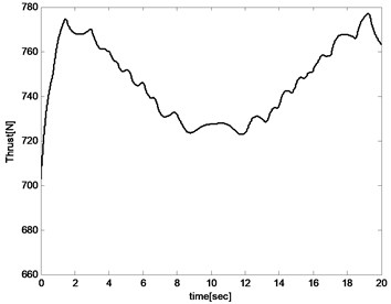
The altitude respond, velocity respond, angle of attack, elevator angle, propulsion force, pitch rate and pitch angle are then plotted to illustrate the feasibility of the proposed controller. Simulation results are presented in Fig. 8-Fig. 14. As shown in Fig. 8 and Fig. 9, the altitude tracking error is less than 0.2 m while the velocity tracking error is less than 0.25 m/s. The tracking errors are used to generate thrust and elevator deflection which reduce the tracking errors adversely. They cannot be eliminated for that the trim condition is always changing during the wing transition process, but can be further decreased by adjusting control parameters. The results illustrate that the proposed controller can accomplish the altitude and the velocity keeping during the wing transition process including sweeping forward and backward.
Fig. 8Altitude
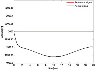
Fig. 9Forward velocity
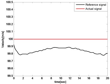
Fig. 10Pitch angle
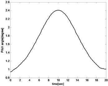
Fig. 11Angle of attack
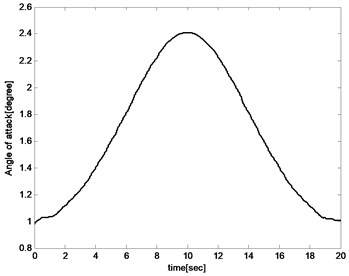
The pitch angle and angle of attack increases with the sweep angle rising for the reason that the lift coefficient decreased with the increase of the sweep angle during the aircraft sweeping backward process. And the angle of attack and pitch angle must be increased to improve lift to maintain the balance of the aircraft as shown in Fig. 10 and Fig. 11. And for the same reason, the angle of attack and pitch angle decreases during sweeping forward process. The pitch rate fluctuates in a small range because the object is to keep the altitude unchanged as presented in Fig. 12.
Fig. 12Pitch rate
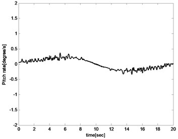
Fig. 13Elevator deflection
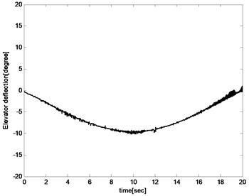
The control input including elevator deflection and propulsion thrust are presented in Fig. 13 and Fig. 14. The changes in elevator defection and thrust are both within acceptable ranges. In the first 10 s, elevator deflection and propulsion thrust have a decreasing trend while an increasing trend in the last 10 s. The reason is that the aircraft sweeps backward in the first 10 s which leads to decreasing of drag coefficient and pitch coefficient. And then elevator deflection and propulsion thrust must also be reduced to keep the balance. In the last 10 s, the situation is the opposite of the front.
Fig. 14Propulsion thrust
In the following section, the advantages of the proposed controller are illustrated. The conventional controller design methods for the variable aircraft are at the basis of linear control with linearized model or linear input variable model as illustrated in Introduction section. Those linear methods highly depend on the prior accurate aerodynamic parameters, which are strict for morphing controller design. The state of art nonlinear controller for the variable aircraft is called “first-order sliding mode differentiator (FOSD)” proposed by Wu [12]. FSOD method could guarantee the tracking errors bounded by and which cannot be set to be near zero as illustrated in Eq. (63) of reference [12]:
And so:
The bound of determines the bound of the tracking error, but not converge to an arbitrary small neighborhood of the origin. The proposed controller of this paper has the ability to converge the tracking errors to an arbitrary small neighborhood of the origin via choosing designed parameters appropriately. Besides, FSOD has three disadvantages compared with proposed controller of our paper:
First, the FSOD method is based on nonlinear dynamic model but still has the assumption on the flight path angle (sin ). It is not a complete nonlinear model and the assumption has been removed in our paper.
Second, a prior knowledge of bounds of tracking errors is required to determine the bounds and of barrier Lyapunov function (BLF) because the tracking errors must be smaller than the bounds that , which may be very difficult to acquire because the whole selected parameters in , , , of reference [12] have influence on the bound of tracking errors. Therefore, repeated parameters selection must be done to acquire the smaller usable bound , not to mention the parameter optimization. Otherwise, the tracking errors may reach and get out of the bound which would cause severe shock of the system. So, the prior of the tracking errors must be acquired to select and then design the controller for FSOD. This problem is removed in our paper.
Third, the dynamic structure is ignored in FSOD that a signal NN is used to approach the unknown control input function (Eq. (5) of reference [12]). This improves the complexity of neural networks and increases the amount of computation. In our paper, the control input is separated from the unknown function and the unknown coefficient of control input is updated by adaptive law which decreases the computation.
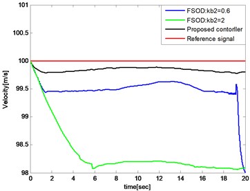
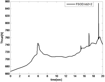
The compared simulations are illustrated below and the controller parameters of FSOD method are selected equally from reference [12]. As shown in Fig. 15, the altitude tracking errors have little diffidence between FSOD and the proposed controller. In Fig. 16, 0.6 and 2 are selected for that we do not know a prior bound knowledge of velocity tracking error. The velocity tracking error reaches and gets out of the bound when 0.6 and it causes severe shock of the system as shown in Fig. 17.
Fig. 15Comparation of altitude tracking errors
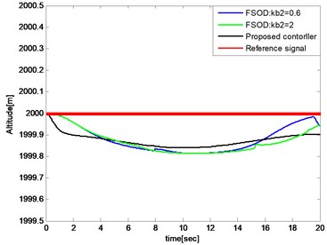
Fig. 16Comparation of velocity tracking errors
When expensed to 2, the velocity tracking error would keep in the bound that and the thrust is illustrated in Fig. 18. Compared with the proposed controller illustrated in Fig. 13, the controller input is unsmooth.
Fig. 17Severe shock of the system
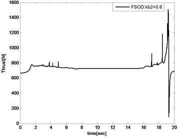
Fig. 18Thrust of FSOD method
7. Conclusions
In this paper, a nonlinear adaptive NN controller is proposed using MLP and DSC techniques while the filter errors are considered. The semi-global boundedness and convergence of all the signals of the closed-loop system is proved according to the Lyapunov-LaSalle invariant set theorem. Simulation results are presented to illustrate that the controllers can track the designed trajectory during wing transition process in the level flight phase and even in the maneuvering phase. Next, parameter optimization would be the focus of the research.
References
-
Prabhakar N., Prazenica R., Gudmundsson S., Balas M. Transient dynamic analysis and control of a morphing UAV. AIAA Guidance, Navigation and Control Conference, San Diego, USA, 2016.
-
Weisshaar T. A. Morphing aircraft systems: historical perspectives and future challenges. Journal of Aircraft, Vol. 50, Issue 2, 2013, p. 337-353.
-
Seigler T. M., Neal D. A. Modeling and flight control of large-scale morphing aircraft. Journal of Aircraft, Vol. 44, Issue 4, 2007, p. 1077-1087.
-
Zheng M. M., He Z., Yin M. Control-oriented modeling and analysis of longitudinal dynamics of variable-Sweep aircraft. IEEE Chinese Guidance, Navigation and Control Conference, Yantain, China, 2014.
-
Baldelli D. H., Lee D. H., Peña R. S. S., Cannon B. Modeling and control of an aeroelastic morphing vehicle. Journal of Guidance Control and Dynamic, Vol. 31, Issue 6, 2008, p. 1687-1699.
-
Ting Y., Wang L. X., Ai J. Q. Gain self-scheduled H∞ control for morphing aircraft in the wing transition process based on an LPV model. Chinese Journal of Aeronaut, Vol. 26, Issue 4, 2013, p. 909-917.
-
Jiang W., Dong C., Wang Q. A systematic method of smooth switching LPV controllers design for a morphing aircraft. Chinese Journal of Aeronaut, Vol. 28, Issue 6, 2015, p. 1640-1649.
-
Wang T., Dong C., Wang Q. Finite-time boundedness control of morphing aircraft based on switched systems approach. Optik, Vol. 126, Issue 23, 2015, p. 4436-4445.
-
Chakravarthy A., Grant D. T., Lind R. Time-varying dynamics of a micro air vehicle with variable-sweep morphing. Journal of Guidance control and Dynamics, Vol. 35, Issue 3, 2012, p. 890-902.
-
Shi R. Q., Peng J. Morphing strategy design for variable-wing aircraft. 15th AIAA Aviation Technology, Integration, and Operations Conference, Dallas, TX, USA, 2015.
-
Wu Z. H., Lu J. C., Rajput J., Shi J. P., Ma W. Adaptive neural control based on high order integral chained differentiator for morphing aircraft. Mathematical Problem in Engineering, 2015, p. 787931.
-
Wu Z. H., Lu J. C., Qing Z., Shi J. P. Modified adaptive neural dynamic surface control for morphing aircraft with input and output constraints. Nonlinear Dynamics, Vol. 87, 2017, p. 2367-2383.
-
Feng J. F., Li Y. L., Xu B. W. Minimum thrust of a morphing unmanned submersible aerial vehicle in the water-to-air motion. Transactions of FAMENA, Vol. 40, Issue 4, 2017, p. 69-82.
-
Hoak D. E., Fink R. D. USAF Stability and Control Datcom. Flight Control Division, Air Force Flight Dynamics Laboratory, Wright-Patterson Air Force Base, Ohio, 1978.
-
Prabhakar N., Prazenica R. J., Gudmundsson S. Dynamic analysis of a variable-span, variable-sweep morphing UAV. IEEE Aerospace Conference, Big Sky, 2015.
-
An J. G., Yan M., Zhou W. B., Sun X. H., Yan Z. Aircraft dynamic response to variable wing sweep geometry. Journal of Aircraft, Vol. 25, Issue 3, 1986, p. 216-221.
-
Bu X., Wu X., Ma Z., Zhang R., Huang J. Novel auxiliary error compensation design for the adaptive neural control of a constrained flexible air-breathing hypersonic vehicle. Neurocomputing, Vol. 171, 2016, p. 313-324.
-
Ruiz Duarte J.-E., Loukianov A. G. Higher order sliding mode control for autonomous underwater vehicles in the diving plane. IFAC, Vol. 48, Issue 16, 2015, p. 49-54.
-
Lasalle J. P. Stability theory for ordinary differential equations. Journal of Differential Equations, Vol. 4, Issue 1, 1968, p. 57-65.
-
Wen Y. T., Ren X. M. Neural networks-based adaptive control for nonlinear time-varying delays systems with unknown control direction. IEEE Transactions on Neural Networks, Vol. 22, Issue 10, 2011, p. 1599-1612.
-
Wang D., Huang J. Adaptive neural network control for a class of uncertain nonlinear systems in pure-feedback form. Automatica, Vol. 38, 2002, p. 1365-1372.
-
Zou A. M., Hou Z. G. Adaptive control of a class of nonlinear pure-feedback systems using fuzzy backstepping approach. IEEE Transactions on Fuzzy Systems, Vol. 16, Issue 4, 2008, p. 886-897.
Cited by
About this article
This work is supported by National Natural Science Foundation of China No. 51779263.

