Abstract
In rotor-bearing system, the misalignment can lead to secondary faults, such as the rub-impact fault. How the development of misalignment could affect the rub-impact force and other dynamic responses is important for the vibration control and fault diagnosis of rotor system. In this paper, a mathematical model of a two-shaft rotor-bearing- gear coupling system is established. The model is validated through the misaligned force of gear coupling, the supporting force of the lubricated ball bearing and the whole rotor response. To overcome the limit of traditional approaches and further dig out fault characteristics, the time-frequency method is introduced to analyze the dynamic response from both the time and frequency domains points of view. It is found the misalignment effect on rotor dynamic responses is mainly focused in high rotating speed range. The development of misalignment has an obvious adverse effect on the rotor stability. Some intermittent components in low frequency range due to the occurrence and development of misalignment can be found affecting the rotor stability at low speed range, and the high frequency rub-impact components can be found responsible for the unstable state of rotor.
1. Introduction
For high efficiency, the clearance between the rotor and the stator is decreasing in rotating machineries. In this circumstance, the rotor and the stator are prone to rub-impact fault which can be considered as a secondary fault caused by unbalance, misalignment and other faults. The rub-impact fault can lead to abnormal vibration, overheat and component wearing [1].
In terms of the influence factors of the rub-impact fault, the effects of stiffness, damping, and mass imbalance on the radial rub-impact fault are most discussed. Patel et al. [2] investigated the nonlinear lateral-torsional vibration characteristics of a rotor contacting a viscos-elastically suspended stator, and found that the friction coefficient, the rotor-stator relative inertia and the contact damping have nonlinear complex effects on the motion characteristics. Liu et al. [3] established a rub-impact model considering the influence of the speed whirling and the radial-torsional coupling, and analyzed the dynamics characteristics of the radial, the whirl and torsional vibration under no rub, full annual rub and partial rub conditions. Yuanet et al. [4] studied the influence of a radial rub-impact on the imbalance response of a rotor and found that the magnitude of the lateral response decreased while that of the torsional response increased with a growing radial rub-impact fault. Although the effects of rotor properties on the rub-impact fault has been studied, the influence of other faults on the rub-impact has not been well discussed, such as how the misalignment could affect the dynamic response of a rub-impact rotor system.
However, the rubbing fault always occurs along with another fault, and the misalignment is a common twinborn fault resulting in the rubbing fault. Many researchers have studied the dynamic characteristics of coupling with misalignment. A two-shaft Jeffcott rotor with rigid coupling was developed to investigate the effect of misalignment on the lateral and torsional responses of the rotor system [5]. In order to study the effects of coupling, Zhao [6] derived a dynamic meshing force model for the gear-spline coupling according to the classic deformation theory of gear tooth and obtained the characteristics of the coupling meshing force. It is found that the meshing forces in the and directions are identical with no misalignment, change nonlinearly when the misalignment is small, and vary linearly when the misalignment gets larger. Zhao [7] and Al-Hussain [5] investigated the effect of the parallel misalignment on the lateral and torsional responses of two rotating shafts. Paolo [8] proposed a simulation method to describe the behavior of a real shaft supported by several oil film bearings, and analyzed the nonlinear effects caused by the rigid coupling misalignment.
About the coupling fault of the rub-impact and the misalignment, Huang and Zhou [9] studied the vibration characteristics of the rotor system with the parallel misalignment and the rub-impact, and analyzed the effect of the parallel misalignment, the bearing stiffness and the mass eccentricity on the system dynamic behavior. It should be noticed that the meshing force of the coupling was ignored in that study. Fu [10] used a series of methods which including experiment and simulation to study the nonlinear characteristics of a rotor system with misalignment and rub fault. Zhang and Ma [11] studied dynamic responses of a rotor-ball-bearing system with a misalignment and rub-impact coupling fault, in which the effect of the Elasto-Hydrodynamic Lubrication (EHL) on system dynamics was the main content. They also established a two-stage rotor system connected by a gear coupling and supported on ball bearings and study the non-linear dynamics of the system under misalignment fault [12]. But they only studied the dynamic characteristics of misalignment-rubbing fault, but less studied on the influence factors on the rub characteristics. There still needs a further study on the connection between the rub-impact faults and the induced failure.
Most of the previous researches were focused on numerical simulations and vibration characteristics of faults system. However, it has been proved that vibration signals are non-stationary and time-varying due to the change of rotational speed and the nonlinear vibration of a faulty rotor system [13]. In order to improve the ability of fault diagnosis, numbers of methods have been proposed for signal processing, condition monitoring and pattern identification [14-17]. Gu [18-20] proposed a series of novel algorithms benefiting the vibration signal processing and fault diagnosis. Time-frequency analysis is an effective tool to extract machinery health information because it can identify the signal frequency components to reveal their time variant features. Wang [21] investigated the effect of signal decomposition methods on time-frequency analysis and found that only using the empirical mode decomposition (EMD) method is not appropriate for realistically decomposing the vibration signal. Zhang and Ma [22] proposed an improved EMD method on time-frequency analysis and applied it on rotating machine fault diagnosis.
In this paper, a rotor-bearing-gear coupling system model with rub-impact and misalignment faults is developed. The improved ball bearing model is built up considering the EHL condition, and the meshing force is taken into account in the gear coupling model for connecting the two rotor sections. The effect of misalignment on the rub-impact rotor dynamic responses is analyzed using bifurcation diagram, Pointcaré map, spectrum diagram and time-frequency analysis.
2. Model descriptions
2.1. Misaligned gear coupling
When the gear coupling is misaligned, the male and female couplings are not concentric (as shown in Fig. 1). The gear teeth on one side tightly mesh with the sleeve while those on the other side contact loosely. In this condition, the meshing force can be divided into: (a) the meshing force associated with torque and (b) the meshing force associated with dynamic vibration.
a) Meshing force associated with torque.
When the gear teeth are in contact with the sleeve to transmit a torque, the meshing force is affected by three factors: the torque-induced deformation, the meshing distance and the meshing stiffness. According to [7], the meshing force caused by the torque can be obtained:
where is the meshing force associated with torque, is the deformation angle of gear tooth, is the equivalent meshing distance of gear tooth, and is the meshing stiffness of gear tooth. The of all the gear teeth are identical under a static driven torque.
b) Meshing force associated with vibration.
During the torque transmission, the vibration of the rotor system leads to a relative movement between the meshing tooth and sleeve. The meshing force associated with vibration can be expressed as:
where is the meshing force caused by vibration, is the position angle of gear tooth, and is the misalignment of gear coupling.
Without torque the meshing force is zero and independent to the vibration displacement. Since the meshing force cannot be negative, the total meshing force of the th tooth can be expressed as:
The meshing forces in the and directions are as follows:
c) Misalignment force
In this study, the misalignment takes place at the gear coupling and produces two forces affecting the dynamic characteristics of the rotor system: the meshing force and the misalignment force. The misalignment forces in the and directions of the rotor system are expressed as [11]:
where and are the movements of the intermediate tooth of gear coupling, is the mass of the intermediate tooth of gear coupling, is the angle velocity, is the initial phase. Since the intermediate tooth has to satisfy both couplings at the same time that misalignment occurs, its rotating angle velocity is related with the rotor speed and the orbit is a circle.
2.2. Ball bearing
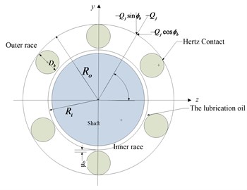
The schematic diagram of the force applied on a ball bearing is shown in Fig. 2. Based on the Hertzian contact [23], the contact stiffness of the ball bearing can be determined as follows [24]:
where is the contact stiffness of ball bearing. is the load of ball, is the contact deformation coefficient of the ball, and is the centrifugal force of the ball. The subscript means the th rolling element.
Fig. 1The Schematic diagram of gear coupling
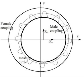
Fig. 2The Schematic diagram of ball bearing
Due to the existence of oil film, the lubrication between rolling element and races should be considered. Under the EHL condition, the oil film pressure is close to Hertzian contact stress in most of the contact zone, but quite different at the entering and departing ends.
According to the pervious study [12], it is found that most of the oil film clearances in the contact zone are nearly unchanged, so the central oil film clearance can be used as equivalent. In the case of point-contact, the oil film thickness equation is suitable for the ball bearing:
where is the non-dimensional central oil film clearance, is a non-dimensional velocity parameter, is a non-dimensional material parameter, is a non-dimensional load parameter, is the ellipticity of the rolling element, is the dynamic viscosity, is the linear velocity, is the equivalent Young’s modulus, is the Poisson’s ratio, is the pressure-viscosity coefficient, and is the curvature radius.
Then the oil film stiffness between the rolling element and the inner race can be calculated:
The oil film stiffness between the rolling element and the outer race can be calculated in the same way. Thus, the overall oil film stiffness can be obtained:
So, the global stiffness and the radial contact load of the th rolling element are as follows:
2.3. Rub-impact fault
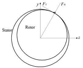
As shown in Fig. 3, the rub-impact force can be decomposed into a radial force and a tangential force :
where , is the radial clearance between the rotor and the stator, is the radial stiffness coefficient of the stator wall, and is the radial friction coefficient between the rotor and the stator.
Fig. 3The schematic of rub-impact forces
Then the rub-impact forces in the and directions can be given as:
2.4. Equations of motion
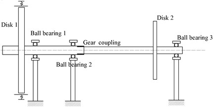
In this study, the rotor system (shown in Fig. 4) consists of two shafts, two disks, three ball bearings and one gear coupling. The rotor is supported in a m pressure is Disk 1 is mounted on the left end of Shaft 1 which is supported by Ball bearings 1 and 2, and Disk 2 is associated with Shaft 2 which is supported by Ball bearing 3 at the right end. The two shafts are connected by the gear coupling.
Fig. 4The model of the rotor-bearing-SFD system
Two assumptions are made as below:
1) The deformations of the journals, the disks, the gear coupling, and the ball bearings are ignored. So, the rotor system is dispersed into 11 lumped mass points connected by mass less shaft sections with axial stiffness;
2) The displacements of the rotor in the axial and torsional directions are negligible so that each mass point has four degrees of freedom including two translations in the lateral and vertical directions and two rotations about the lateral and vertical directions.
The equations of motion of the rotor system are derived as:
where and are the masses of Disk 1 and Disk 2, to are the masses of shaft sections, and are the viscous damping factors of disks and ball bearings, is the stiffness of shaft sections, and are the rub-impact forces in the lateral and vertical directions, and are the supported forces of ball bearings in the lateral and vertical directions, and are the misalignment forces in the lateral and vertical directions, and are the meshing forces in the lateral and vertical directions, and and are the eccentricities of Disk1 and Disk 2.
2.5. Numerical method
In this paper, equations of motion are solved by the fourth order Runge-Kutta method, and the time step in the iterative procedure is set as 1×10⁻⁵ s. The time varying data corresponding to the first 500 periods generated by numerical integration are deliberately excluded in order to discard the transient solutions. The parameters used are listed in Table 1.
2.6. Time-frequency method
Due to the nonlinearity of the system response and the frequency overlap of fault characteristic, traditional features obtained from bifurcation diagram, Pointcaré map and frequency spectrum are not enough for analyzing the faulty rotor system. In this paper, the time-frequency method is employed to dig out more fault information that hidden from time and frequency domains. To this end a wavelet packet decomposition (WPD) improved EMD technique is applied to solving the problem [22]. Although a vibration signal can be decomposed into several IMFs by EMD, some high-frequency small-amplitude harmonics cannot be separated from one modulated IMF. So, the WPD is used to further decompose an IMF into narrow bands. In this way, some discontinuous high frequency contents can be found to illustrate the rub-impact fault. The time-frequency analysis can be operated in four steps:
1) Decompose the vibration signal by EMD method;
2) Further decompose the obtained IMFs using WPD technique and reform the WP coefficients;
3) Choose reformed IMFs that of high concerns as the first IMFs according to the node energy and the correlation between the reformed and original IMFs, and add other IMFs into the residual;
4) Apply Hilbert transform to the new-generated IMFs to obtain the time-frequency distribution of the vibration signal.
Table 1Parameters of the rotor-bearing system
Parameter | Value | Parameter | Value |
15.78 kg | 2.25 kg | ||
5.23 kg | 1.61 kg | ||
3.7 kg | 2.5×10⁷ N/m | ||
2.3 kg | 800 Ns/m | ||
1.1 kg | 1500 Ns/m | ||
2.25 kg | 2×10⁷ N/m | ||
2.25 kg | 3.5×10⁻⁵m |
3. Model validation
3.1. Ball bearing model
To validate the ball bearing model developed in this paper, the calculation results are compared with the results in [25]. The comparison is conducted using the information in frequency domain. Fig. 5(a) shows the results from [25] and Fig. 5(b) is the results from the model.
From both results, it is found that when the speed is far from the critical speeds the motion of the rotor mainly represents at the ball passage frequency and relevant harmonic components. The amplitude of vibration at the VC frequency is far higher than the following harmonics and decreases with increasing VC frequencies. Although the rotor speed is different, the vibration amplitude distribution along the frequency range in this paper is exactly in the same pattern as Ref [25], and both results show the motions are periodic. As a conclusion, the ball bearing model developed in this paper is validated.
3.2. Gear coupling model
In order to verify the misalignment model of the gear coupling, the simulation results of the proposed model are compared with the results of [7]. In the simulation, the vibration displacements in the and directions are both 0.001 mm, the static misalignment changes from 0 to 0.2 mm, and the deformation angle of gear tooth is 0°. The meshing forces in the and directions are shown in Fig. 6. From the comparison, it is found that the two components of meshing force of the proposed model are in the same pattern as the results of [7]. The difference in the amplitude of meshing force is because the transmitted torque is much smaller than that in the reference due to the rotor structure. When the misalignment is zero, the meshing forces in the two directions are the same. With increasing misalignment, the magnitudes of meshing forces in the two directions begin to increase sharply within the misalignment range from 0 to 1×10‒4 m. As the misalignment further increases, the two components of meshing force increase very slow and reach stable levels until the end. Obviously, the model developed in this paper is able to reflect the dynamic behavior of gear coupling correctly.
Fig. 5Rotor responses in the x direction: a) in this paper, b) in [25]
![Rotor responses in the x direction: a) in this paper, b) in [25]](https://static-01.extrica.com/articles/18476/18476-img5.jpg)
a)
![Rotor responses in the x direction: a) in this paper, b) in [25]](https://static-01.extrica.com/articles/18476/18476-img6.jpg)
b)
Fig. 6Meshing forces under different misalignments: a) in this paper, b) in [7]
![Meshing forces under different misalignments: a) in this paper, b) in [7]](https://static-01.extrica.com/articles/18476/18476-img7.jpg)
a)
![Meshing forces under different misalignments: a) in this paper, b) in [7]](https://static-01.extrica.com/articles/18476/18476-img8.jpg)
b)
3.3. Rotor system model
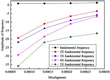
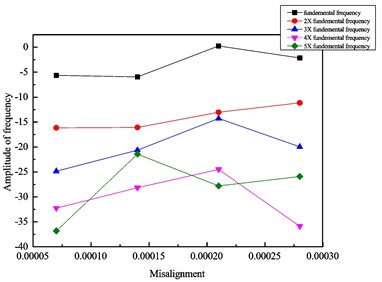
To examine the rotor model, a group of experimental results [12] under different misalignments are used. The comparison between the simulation and the experiments are given in Table 2 and Fig. 7.
Fig. 7Vibration amplitudes of: a) simulation, b) experiment with increasing misalignment
a)
b)
Table 2Comparison between simulation and experimental results with different misalignments
Misalignment (m) | Amplitude at fundamental frequency and harmonics | |||||||||
1× | 2× | 3× | 4× | 5× | ||||||
sim | test | sim | test | sim | test | sim | test | sim | test | |
0.7×10⁻⁴ | 0.95 | –5.62 | –19.28 | –16.14 | –21.86 | –24.85 | –29.32 | –32.25 | –35.82 | –36.81 |
1.4×10⁻⁴ | 0.95 | –5.96 | –10.98 | –16.07 | –13.71 | –20.62 | –18.50 | –28.14 | –21.92 | –21.43 |
2.1×10⁻⁴ | 1.10 | 0.25 | –6.56 | –13.02 | –9.01 | –14.27 | –11.00 | –24.48 | –18.71 | –27.81 |
2.8×10⁻⁴ | 1.37 | –2.16 | –3.54 | –11.16 | –5.81 | –19.94 | –6.68 | –35.87 | –16.61 | –25.89 |
As the misalignment changes, both simulation and experimental amplitudes varies obviously. For the simulation, the amplitudes at all frequencies increase with increasing misalignment. For the experiment, the amplitudes at the fundamental frequency increases monotonously with increasing misalignment, while the amplitudes at other harmonic frequencies increase first then decrease at the end. The reason of this different trend may be the increase of misalignment in the gear coupling leads to a misalignment between the drive motor and the rotor which can bring unpredictable effect on the vibration of rotor system. This conclusion can be found in [26] as well. So, the mathematical model of the two-shaft rotor-bearing system with a misaligned gear coupling can be validated.
4. Results and discussion
4.1. Rub-impact analysis under misalignments
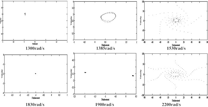
For the rotor system under rub-impact fault but without misalignment, the bifurcation diagram and Pointcaré maps are shown in Fig. 8 and Fig. 9 respectively. The motion of the rotor system is periodic in the rotating speed range of 1000 rad/s to 1650 rad/s and becomes quasi-periodic in the range of 1650 rad/s to 1800 rad/s. Two following jump points appear at 1810 rad/s and 1815 rad/s. Then the motion returns to periodic until 1930 rad/s and goes into quasi-periodic again from 1935 rad/s to 2005 rad/s. Between 2005 rad/s and 2200 rad/s, the motion alternates between period-one and period-two. After that, the motion of the rotor loses its regularity and falls into quasi-period.
Fig. 8Bifurcation diagram of the rotor system under rub-impact fault without misalignment

Fig. 9Pointcaré maps of the rotor system under rub-impact fault without misalignment
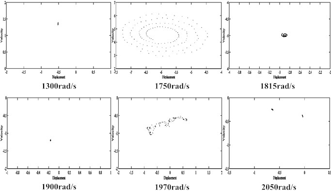
Under 1×10‒5 m misalignment, the bifurcation diagram of the rub-impact rotor system is shown in Fig. 10 and the corresponding Pointcaré maps are shown in Fig. 11. The motion of the rotor is period-one from 900 rad/s to 1450 rad/s. In the range of 1450 rad/s and 1800 rad/s, the motion of the rotor is quasi-period and jumps at 1805 rad/s, 1810 rad/s, 1815 rad/s and so on. From the last jump point to 2270 rad/s, the motion of the rotor is unstable and goes into chaos. Then the motion becomes periodic from 2275 rad/s to 2345 rad/s and finally returns to quasi-periodic.
Fig. 10Bifurcation diagrams of the rub-impact rotor system with 1×10‒5m misalignment

Fig. 11Pointcaré maps of the rub-impact rotor system with 1×10‒5 m misalignment
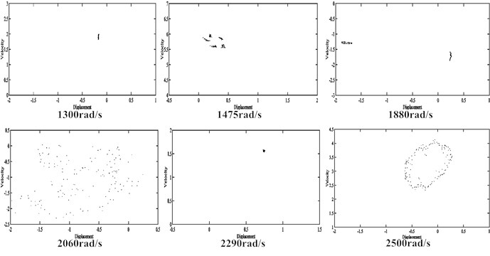
When the misalignment is increased to 1.4×10‒1 m, the bifurcation diagram of the rub-impact rotor system is shown in Fig. 12 and the corresponding Pointcaré maps are shown in Fig. 13. The dynamic orbit shows period-one motion when the rotating speed is below 1375 rad/s. As the rotor speed increases to 1590 rad/s, the motion of rotor loses its stability and falls into chaos. After that the motion returns to period-one from 1595 rad/s to 1645 rad/s and goes into quasi-period from 1650 rad/s to 1805 rad/s. After a series jump points, the motion of rotor goes back to period-one in a short range of 1810 rad/s to 1840 rad/s, becomes quasi-period from 1845 rad/s to 2240 rad/s, and then falls into chaos. At the end, the system stability improves but the motion of rotor is still in quasi-period.
Fig. 12Bifurcation diagrams of the rub-impact rotor system with 1.4×10‒4 m misalignment

It can be concluded the rub-impact rotor system is always stable at lower speed regardless misalignment. But increasing misalignment can bring the motion of rotor into quasi-period earlier and enlarge the speed range of quasi-period/chaos motion. In other words, the stability of rotor system decreases with increasing misalignment. However, the motions of rotor are unusual that returns to periodic from quasi-periodic in some high-speed ranges, which is further discussed in the next section.
Fig. 13Pointcaré maps of the rub-impact rotor system with 1.4×10‒4 m misalignment
4.2. Effect of misalignment on rotor dynamics
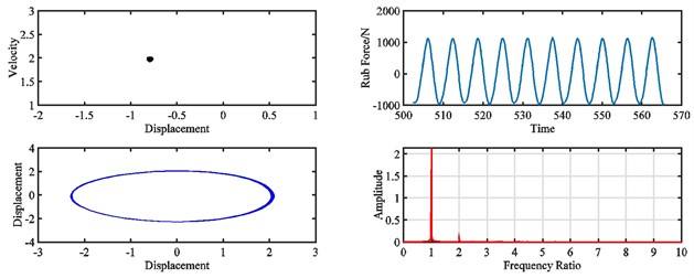
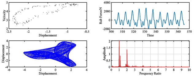
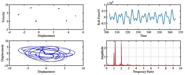
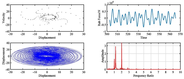
Fig. 14 shows the bifurcation diagram of the rub-impact rotor system with varies of misalignments under 1500 rad/s. It can be found that the dynamic orbit shows period-one with increasing misalignment from 0 to 3×10‒5 m. In this misalignment range, the rub-impact force is periodic and vibration amplitudes only can be found at fundamental and 2× fundamental frequencies in the spectrum diagram. With increasing misalignment, the peak rub-impact force increases from 1000 N to 6757 N, the variation of rub-impact force is irregular, the motion of rotor system is more unstable, and vibration at some low frequencies can be found around the fundamental frequency.
Fig. 14Bifurcation diagram of the rub-impact rotor with different misalignments under 1500 rad/s
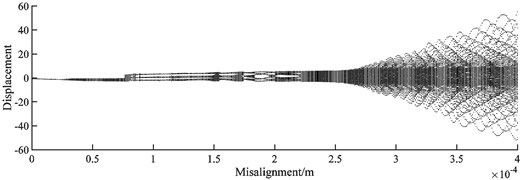
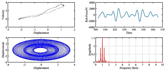
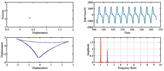
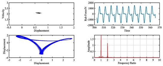
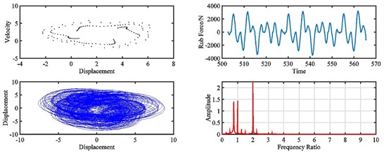
Fig. 16 and Fig. 17 show the dynamic responses of the rotor system with varies of misalignment at 2320 rad/s. It can be found that the motion of the rotor is quasi-periodic when the misalignment develops from 0 to 7.5×10‒5 m.
Without misalignment, the rub-impact force is irregular, and the peak amplitude is 1960 N, and low frequency vibration around the fundamental frequency can be found on the spectrum. As the misalignment grows from 7.5×10‒5 m to 9.3×10‒5 m, the motion of rotor goes into period-one, the peak amplitude of rub-impact force reduces to 1250 N, the force time history becomes more regular, and vibration around the fundamental frequency mitigates a lot. With further increased misalignment, the motion of rotor returns to quasi-period, the rub-impact force becomes irregular again in time domain, the amplitude of rub-impact force is almost doubled, and a considerable vibration peak appears at low frequency.
Fig. 15Pointcaré map, rub force, rotor orbit and spectrum diagram of rub-impact rotor at 1500 rad/s under misalignment of: a) 0 m, b) 5×10‒5 m, c) 1.85×10‒4 m, d) 3.3×10‒4 m
a)
b)
c)
d)
Fig. 16Bifurcation diagram of the rotor system with different misalignments at 2320 rad/s
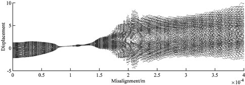
Fig. 17Pointcaré map, rub force, rotor orbit and spectrum diagram of rub-impact rotor at 2320 rad/s under misalignment of: a) 0 m, b) 9×10‒5 m, c) 1.2×10‒4 m, d) 2.2×10‒4 m
a)
b)
c)
d)
4.3. Time-frequency analysis
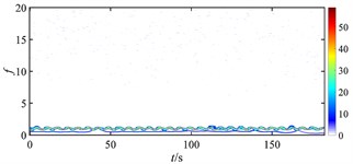
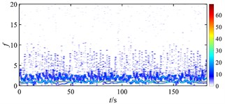
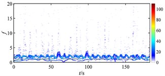
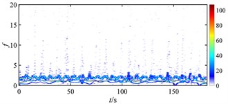
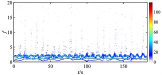
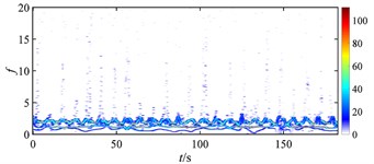
Fig. 18 gives the time-frequency maps of the rub-impact force of rotor under different misalignments. Without misalignment (as Fig. 18(a)), the rub-impact force is nearly continuous with few weak intermittent components at high frequency, and the energy distributes around the fundamental frequency evenly. When the misalignment appears at a relatively low level (as Fig. 18(b)), numbers of intermittent components can be found at low frequency range, the energy distribution is messy, and the magnitude of energy starts to increase. As the misalignment further develops (as Fig. 18(c), (d) and (f)), the intermittent components reduce a lot, the energy distribution of the signal becomes more regular, and the magnitude of energy stops increasing. It can be seen that the occurrence of misalignment has the biggest impact on the rub-impact force of rotor system, which is greatly deteriorated due to a small increment of misalignment from nothing to a very low level. In other words, the stability of rub-impact rotor decreases a lot at the moment that misalignment starts, but stops to further decrease with further increasing misalignment.
Fig. 18Time-frequency maps of rub-impact force at 1500 rad/s under misalignment of: a) 0 m, b) 5×10‒5 m, c) 1.85×10‒4 m, d) 2×10‒4 m, e) 2.4×10‒4 m, f) 3.3×10‒3 m
a)
b)
c)
d)
e)
f)
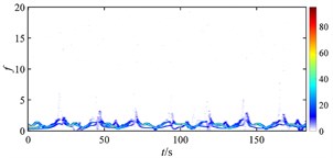
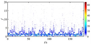
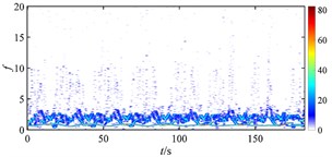
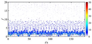
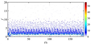
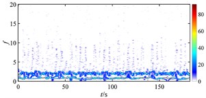
Fig. 19 shows the time-frequency maps of the rub-impact force of rotor under different misalignments at higher rotating speed. When there is no misalignment, it is found that the energy distribution of rub-impact force is not as evenly as that at lower speed (shown in Fig. 18 (a)) due to some low frequency components. When the misalignment is 5×10‒5 m, lots of intermittent components appear at low frequencies which make the energy distribution more irregular, but the magnitude of energy decreases. As the misalignment increases to 9×10‒5 m, the energy of rub-impact force is focused on the fundamental frequency, and more intermittent disturbances spread in low frequency range. But some high frequency components start to show periodic distribution. With increasing misalignment, the magnitude of energy increases, and the distribution is more irregular. Combined with Fig. 17, it can find that the motion of rotor turns from quasi-period to period-one due to the increase of misalignment, but this state is unstable because of the periodic intermittent high frequency rub-impact component. With further development of misalignment, the rub-impact force becomes more irregular and results in chaos of the rotor system.
Fig. 19Time-frequency maps of rub-impact force at 1940 rad/s under misalignment of: a) 0 m, b) 5×10‒5 m, c) 9×10‒5 m, d) 1.2×10‒4 m, e) 2.2×10‒4 m, f) 3×10‒4 m
a)
b)
c)
d)
e)
f)
5. Conclusions
In this paper, a model of a rotor-ball bearing-gear coupling system with rub-impact and misalignment faults is established. The lubrication of ball bearing, and the meshing forces of gear coupling are considered. The effect of misalignment on the rub-impact rotor system is analyzed. Some conclusions are as follows:
1) Misalignment can strongly affect the stability of the rub-impact rotor system at high rotating speed. Both the starting point of quasi-period motion and the range of quasi-period/chaos motion are changed due to the development of misalignment.
2) The motion, orbit and vibration spectrum of the rotor and the rub-impact force are highly related to the change of misalignment. Generally, the development of misalignment brings adverse effect on rotor stability, and the speed range of the unstable motion increases with increasing misalignment. However, the effect pattern still depends on the rotating speed.
3) Unusual effects of misalignment on the rub-impact rotor dynamics can be found at high frequencies which cannot be well explained by bifurcation diagram, Pointcaré map, rotor orbit and frequency spectrum. Using the time-frequency method, some intermittent high frequency rub-impact components can be found responsible for the unstable state of rotor.
4) Some intermittent components in low frequency range due to the occurrence and development of misalignment can be found affecting the rotor stability at low speed range. Since the intermittent disturbances reduce quickly with increasing misalignment, the motion of rotor returns to regular at a constant speed even the misalignment goes worse.
5) Using the time-frequency analysis, some fault characteristics once unable to be observed become visible, in particular for the misalignment-rub-impact coupled fault. It indicates that a qualitative or even quantitative assessment of the fault might be possible on the basis of measurable quantities.
References
-
Li M., Yu L. Analysis of the coupled lateral torsional vibration of a rotor-bearing system with a misaligned gear coupling. Journal of Sound and Vibration, Vol. 243, Issue 2, 2001, p. 283-300.
-
Patel T. H., Zuo M. J., Zhao X. Nonlinear lateral-torsional coupled motion of a rotor contacting a visco-elastically suspended stator. Nonlinear Dynamics, Vol. 69, Issues 1-2, 2012, p. 325-339.
-
Lu W., Chu F. Radial and torsional vibration characteristics of a rub rotor. Nonlinear Dynamics, Vol. 76, Issue 1, 2014, p. 529-549.
-
Yuan Z., Chu F., Wang S., et al. Influence of rotor’s radial rub-impact on imbalance responses. Mechanism and Machine Theory, Vol. 42, Issue 12, 2007, p. 1663-1667.
-
Al Hussain K.-M., Redmond I. Dynamic response of two rotors connected by rigid mechanical coupling with parallel misalignment. Journal of Sound and Vibration, Vol. 249, Issue 3, 2002, p. 483-498.
-
Zhao G. Study on Coupled Dynamics of Rotor-Coupling-Bearing-Isolator System. Harbin Institute of Technology, 2009.
-
Zhao G., Liu Z., Chen F. Meshing force of misaligned spline coupling and the influence on rotor system. International Journal of Rotating Machinery, Vol. 1, Issue 2008, 2008, p. 1-8.
-
Pennacchi P., Vania A., Chatterton S. Nonlinear effects caused by coupling misalignment in rotors equipped with journal bearings. Mechanical Systems and Signal Processing, Vol. 30, 2012, p. 306-322.
-
Huang Z., Zhou J., Yang M., et al. Vibration characteristics of a hydraulic generator unit rotor system with parallel misalignment and rub-impact. Archive of Applied Mechanics, Vol. 81, Issue 7, 2011, p. 829-838.
-
Fu X. Imbalance-misalignment-rubbing coupling faults in hydraulic turbine vibration. International Journal for Light and Electron Optics, Vol. 127, Issue 8, 2016, p. 3708-3712.
-
Zhang J., Ma L., Ma W., et al. Dynamic analysis of rotor-ball bearings system based on elasto-hydrodynamic lubrication with rub-impact-misalignment coupling fault. Journal of Aerospace Power, Vol. 8, 2014, p. 1940-1952, (in Chinese).
-
Ma L., Zhang J., Lin J., et al. Dynamic characteristics analysis of a misaligned rotor–bearing system with squeeze film dampers. Journal of Zhejiang University-Science A, Vol. 17, Issue 8, 2016, p. 614-631.
-
Han, Zhang, Wen, Xue, C. Time-frequency features of two types of coupled rub-impact faults in rotor systems. Journal of Sound and Vibration, Vol. 321, Issue 3, 2009, p. 1109-1128.
-
Deng, Zhao, Zou, et al. L. A novel collaborative optimization algorithm in solving complex optimization problems. Soft Computing, Vol. 21, Issue 15, 2017, p. 4387-4398.
-
Wang B., Gu X., Ma L., Yan S. Temperature Error Correction based on BP Neural Network in Meteorological WSN. International Journal of Sensor Networks, Vol. 23, Issue 4, 2017, p. 265-278.
-
Zhang J., Tang J., Wang T., Chen F. Energy-efficient data-gathering rendezvous algorithms with mobile sinks for wireless sensor networks. International Journal of Sensor Networks, Vol. 23, Issue 4, 2017, p. 248-257.
-
Bi F., Shao K., Liu C., et al. Analysis of thermos elastohydrodynamic performance of journal misaligned engine main bearings. Chinese Journal of Mechanical Engineering, Vol. 28, Issue 3, 2015, p. 511-520.
-
Gu B., Victor Sheng S. A robust regularization path algorithm for ν-support vector classification. IEEE Transactions on Neural Networks and Learning Systems, Vol. 28, Issue 5, 2016, p. 1241-1248.
-
Gu B., Sun X., Victor Sheng S. Structural minimax probability machine. IEEE Transactions on Neural Networks and Learning Systems, Vol. 28, Issue 7, 2016, p. 1646-1656.
-
Gu B., Victor Sheng S., Keng Y. T., Walter R., Li S. Incremental support vector learning for ordinal regression. IEEE Transactions on Neural Networks and Learning Systems, Vol. 26, Issue 7, 2015, p. 1403-1416.
-
Wang T., Zhang M., Yu Q., et al. Comparing the applications of EMD and EEMD on time–frequency analysis of seismic signal. Journal of Applied Geophysics, Vol. 83, 2012, p. 29-34.
-
Zhang J., Ma W., Lin J., et al. Fault diagnosis approach for rotating machinery based on dynamic model and computational intelligence. Measurement, Vol. 59, 2015, p. 73-87.
-
Hertz H. On the contact of elastic solids. Journal Fur Die Reine Und Angewandte Mathematik, Vol. 92, 1881, p. 156-171.
-
Harris T. Rolling Bearing Analysis. John Wiley and Sons, 1991.
-
Zhou H., Luo G., Chen G., et al. Analysis of the nonlinear dynamic response of a rotor supported on ball bearings with floating-ring squeeze film dampers. Mechanism and Machine Theory, Vol. 59, 2013, p. 65-77.
-
Wan Z., Jing J. P., Meng G., et al. Theoretical and experimental study on the dynamic response of multi-disk rotor system with flexible coupling misalignment. Proceedings of the Institution of Mechanical Engineers, Part C: Journal of Mechanical Engineering Science, Vol. 226, 2012, p. 2874-2886.
Cited by
About this article
We are grateful to the Joint Funds of National Science Foundation of China and Civil Aviation Administration Foundation of China (No. U1233201), Major projects of CAAC (MHRD20160106) and National Science Foundation of China (51501222) for providing financial support for this work. The authors declare that there is no conflict of interests regarding the publication of this paper.
Xin Lu designed the study, performed the research, analysed data, and wrote the paper. Junhong Zhang designed research, performed research, analyzed data, and wrote the paper. Liang Ma and Jiewei Lin helped develop the rotor model and validate the model. Jun Wang did some of simulation works, especially on the time-frequency analysis. Jie Wang and Huwei Dai collected the simulation data and help on writing paper.
