Abstract
A three-DOF ultrasonic motor is presented in this paper. The proposed motor consists of four piezoelectric ceramic plates and a mental base with a flange that can fix the motor on a rack. The proposed motor takes advantage of a longitudinal mode and two bending modes, different hybrids of which can realize three-DOF actuation. Because of symmetric structure of the proposed motor, the resonance frequencies of the two bending modes are identical. And the resonance frequency of the longitudinal mode was tuned closed to the ones of the bending modes by adjusting the structural parameters in modal analysis. Then trajectories of nodes on the driving foot were obtained by the transient analysis to verify the feasibility of driving principle. Experiments including vibration shape test and output characteristic test were executed. The starting voltages of the rotation along horizontal axes are about 10 Vp-p. Under driving voltages of 200 Vp-p, the output velocities of three DOF can reach 280 rpm, 277 rpm and 327 rpm, respectively. The results of the experiments indicate that the proposed motor is characterized by low starting voltages and high output velocities.
1. Introduction
Because ultrasonic motors exhibit some merits, such as quick response, high position accuracy, self-locking when power off and non-electromagnetic radiation, they have replaced many electromagnetic motors in several fields such as MEMS (Micro-electro-mechanical Systems), high precision machines and micro robots. Ultrasonic motors work on the principle that alternative electricity can be converted to mechanical vibration via converse piezoelectric effect of the piezoelectric elements, and the vibration of the stator can generate elliptical or oblique movement on the driving foot, and this movement can be converted into the continuous motions via frictional coupling on the interface between the runner and the stator [1-5].
According to the type of the output motion, ultrasonic motors can be classified into linear type, rotary type and multi-DOF one. The linear actuation of ultrasonic motors can be realized by the hybrid of two independent vibration modes, such as a bending and a longitudinal vibration modes [6-10], two bending vibration modes and two longitudinal modes [11-14]. The rotary actuation is usually realized by a traveling wave in a ring-type or cylinder-type stator and can also be realized by the hybrid of two vibration modes [15-19]. The multi-DOF ultrasonic motors need the ability of actuations in several directions. And some of them can realize rotary driving in three different directions. The three-DOF ultrasonic motor proposed by Hoshina et al. [20] consists of three annular stators, each of which uses one traveling wave. The three-DOF ultrasonic motor proposed by Ishii et al. [21] consists of two Langevin transducers, each of which uses multi modes. The three-DOF ultrasonic motor proposed by Shen et al. [22] consists of four symmetric piezoelectric pusher elements, each of which uses three vibration modes. These three ultrasonic motors consist of at least two stators to realize the three-DOF actuations, which makes them much complex to be fabricated. On the other side, ultrasonic motors consist of a single stator have been studied and proposed [23-25]: the ultrasonic motor proposed by Khoo et al. [23] is bonded type, whereas the ultrasonic motors proposed by Takemura et al. and Li et al. [24-25] belong to the bolt-clamped type. And the former type is more easily to be fabricated and miniaturized than the latter one. The proposed motor in this paper can realize three-DOF actuations by only one single bonded-type stator, which can reduce the volume and mass of the motor. Because the frequencies of vibration modes this motor used are easy to be tuned closed, it is convenient to adjust the dimensions of the motor to be apply it in different situations, such as driving the ‘eyes’ of a robot.
2. Actuator concept
In order to realize three-DOF actuation, the proposed motor is designed to use different hybrids of three vibration modes: a longitudinal vibration mode and two orthogonal bending vibration modes.
2.1. Geometry
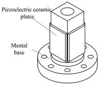
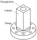
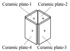
The structure of the proposed motor is shown in Fig. 1. The proposed motor consists of four pieces of piezoelectric ceramic plates and a metal base as shown in Fig. 1(a). It can be seen in Fig. 1(b) that the metal base is an integration of a cuboid to be attached with piezoelectric ceramic plates and a flange with eight holes to fix the motor on a rack. There is a through-hole in the metal base to tune the resonance frequencies of three vibration modes and to work as a driving foot. The polarization directions and serial numbers of the piezoelectric ceramic plates are shown in Fig. 1(c). These four pieces of piezoelectric ceramic plates are all polarized along the direction of thickness and each two parallel piezoelectric ceramic plates are polarized in same direction. Thus, the hybrid of two bending vibration modes can be excited by two driving signals. The hybrid of the longitudinal and a bending vibration mode need three driving signals.
Fig. 1The structure of the proposed motor: a) the three-dimensional model of the proposed stator, b) the metal base of the proposed motor, c) the polarizations of PZT ceramics
a)
b)
c)
2.2. Driving principle
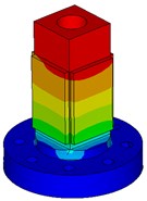
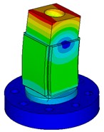
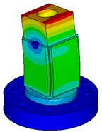
The first order longitudinal vibration mode and two second order bending vibration modes are selected and their mode shapes are shown in Fig. 2(a), (b) and (c), respectively. The proposed motor will be excited by two or three driving signals shown in Fig. 3, with the metal base connected to ground. It can be seen from the Fig. 3 that there is a phase shift of 90 degrees between signal-1 and signal-2; the voltage change of signal-3 is converse with the one of signal-1.
Fig. 2Selected vibration modes of the proposed motor: a) the first order longitudinal vibration mode, b) the second order bending vibration mode, c) the second order bending vibration mode
a)
b)
c)
Fig. 3Driving signals of the proposed motor
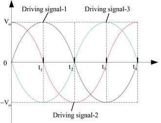
The proposed motor can realize rotation along axis-Z by the hybrid of two orthogonal bending vibration modes. The driving signal-1 and driving signal-2 are applied on each two parallel pieces of piezoelectric ceramic plates, namely, the driving signal-1 is applied to ceramic plate-1, 3 and the driving signal-2 is applied to ceramic plate-2, 4, respectively. Under this circumstance, the bending vibration in plane-YOZ is excited by the ceramic plate-1, 3 while the bending vibration in plane-XOZ is excited by the ceramic plate-2, 4. Since there is a phase shift of 90 degrees between driving signal-1 and driving signal-2, an elliptical movement trajectory in plane-XOY of the driving foot can be accomplished by the superposition of these two bending vibrations, as shown in Fig. 4.
Fig. 4Operating sequence of rotation along axis-Z: a) the vibration state of the proposed motor when t=t0 or t=t4, b) the vibration state of the proposed motor when t=t1, c) the vibration state of the proposed motor when t=t2, d) the vibration state of the proposed motor when t=t3

When t=t0or t=t4, |V1|= 0 and |V2|=Vm, the deformations of ceramic plate-2, 4 reaches maximum with ceramic plate-1, 3 getting no deformation and the vibration state of the proposed motor is shown in Fig. 4(a). Then, |V1| increases and |V2| decreases. The deformations of corresponding ceramic plates are in identical tendency with the voltage changes. At the same time, the vibration state of the proposed motor changes from what is shown in Fig. 4(a) to the one shown in Fig. 4(b). The next two states can be reached in rest part of a period. Finally, the rotation along axis-Z of a runner can be actuated.
The proposed motor can realize rotation along axis-Y by the hybrid of the bending vibration in plane-XOZ and the longitudinal vibration. The driving signal-2 is applied on the two pieces of piezoelectric ceramic plates parallel with plane-YOZ, namely, ceramic plate-2, 4. The driving signal-1and 3 are applied on the two pieces of piezoelectric ceramic plates parallel with plane-XOZ, namely, ceramic plate-1 and 3, respectively. In this condition, one of the ceramic plate-2 and 4 extends with the other shrinking; both ceramic plate-1 and 3 extend or shrink at the same time. Thus, the bending vibration in plane-XOZ and the longitudinal vibration are excited. With the phase shifts between these three driving signals, the elliptical movement trajectory in plane-YOZ of the driving foot can be realized by the superposition of these two vibrations. When t=t0 or t=t4, |V1|=|V3|= 0 and |V2|=Vm, the deformations of ceramic plate-2 and 4 reaches maximum with ceramic plate-1 and 3 getting no deformation. The state of the proposed motor is shown as Fig. 5(a). Then, |V2| decreases, |V1| and |V3| increase. The deformations of ceramic plate-2, 4 and the degree of the bending vibration diminish. The deformations of ceramic plate-1, 3 and the degree of the longitudinal vibration are enhanced. The state of the proposed motor changes from what is shown in Fig. 5(a) to the one shown in Fig. 5(b). In the rest of a period, states shown in Fig. 5(c) and (d) will be accomplished. Finally, the rotation along axis-Y of a runner can be actuated.
Fig. 5Operating sequence of rotation along axis-Y: a) the vibration state of the proposed motor when t=t0 or t=t4, b) the vibration state of the proposed motor when t=t1, c) the vibration state of the proposed motor when t=t2, d) the vibration state of the proposed motor when t=t3

In a similar way, the proposed motor can realize rotation along axis-X by the hybrid of the bending vibration in plane-YOZ and the longitudinal vibration. The driving signal-2 is applied on the two pieces of piezoelectric ceramic plates parallel with plane-XOZ, namely, ceramic plate-1 and 3. The driving signal-1 and 3 are applied on the two pieces of piezoelectric ceramic plates parallel with plane-YOZ, namely, ceramic plate-2 and 4, respectively.
3. FEM analyses
In order to verify the feasibility of the driving principle presented in last section, the FEM model of the proposed motor is established and analyzed. The material of metal base is aluminum alloy and the PZT ceramic elements are PZT-4.
3.1. Modal analysis
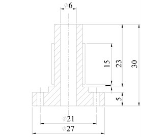
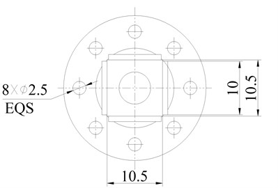
The proposed motor takes advantage of three vibration modes a longitudinal vibration mode and two orthogonal bending vibration modes. The structural parameters of the proposed motor are adjusted to tune the resonance frequencies of these vibration modes close to each other. And it can be found out that the resonance frequencies of the two bending vibration modes will keep the same with the structure symmetric in plane-XOY. Therefore, the main work in this part is simplified and just to tune the resonance frequency of the longitudinal vibration mode close to the one of the bending vibration mode. The resonance frequencies of the longitudinal vibration mode and the bending vibration mode are calculated to be about 40.95 kHz and 41.12 kHz, respectively, and the final dimensions are shown in Fig. 6.
3.2. Transient analysis
After establishing FEM model and accomplishing the parameter design of the proposed motor, it needs to verify the driving principle presented in second section. And the cardinal work in this part is to observe if the driving foot moves in the desired elliptical trajectory.
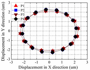
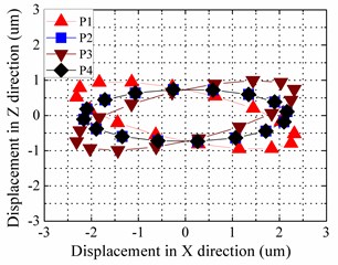
The transient analysis was executed by ANSYS. The driving signals were applied on the FEM model in the ways as shown in driving principle. The frequency and virtual voltage of the driving signals are 40.95 kHz and 100 V, respectively. There are four special points on the driving foot shown in Fig. 7 and the motion trajectories of these four points in last period of the simulation are shown in Fig. 8. The Fig. 8(a) and (b) show the motion trajectories of rotation along axis-Z and axis-Y, respectively. Except the difference in direction, the driving principle of rotation along axis-X is same with the one of rotation along axis-Y. Thus, the rotation along axis-X needn’t to be presented.
Fig. 6Dimensions of the proposed motor (unit: mm)
a)
b)
Fig. 7Selected nodes on the driving foot
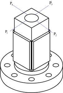
Fig. 8Motion trajectories of selected nodes in the last simulation period: a) trajectories of rotation along axis-Z, b) trajectories of rotation along axis-Y
a)
b)
It can be seen from the Fig. 8(a) that the motion trajectories of the four points are nearly circular. They aren’t overlapped because the selected points of elements in FEM model aren’t exactly at the points shown in Fig. 7. The amplitudes of the two bending vibrations are almost 2.1 um. It can be seen from the Fig. 8(b) that the trajectories of four points are elliptical. P2 and P4 are at the plane-YOZ and long axes of their motion trajectories are parallel with axis-X. The long axes of the P1 and P3’s motion trajectories are a little inclined with the axis-X. The minimal amplitude is the one of the longitudinal vibration, which is about 0.72 um. According to transient analysis, the driving principle is feasible.
4. Experiments
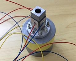
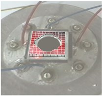
Only finishing FEM analyses is not sufficient to verify the feasibility of the proposed motor. A prototype of the proposed motor was fabricated, as shown in Fig. 9. The results of the experiments are presented in this section.
Fig. 9Prototype of the proposed motor
4.1. Vibration shape test
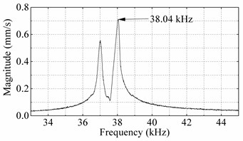
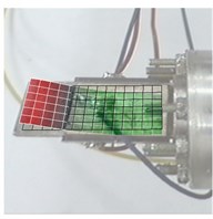
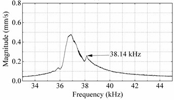
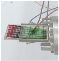
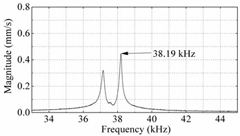
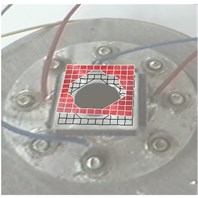
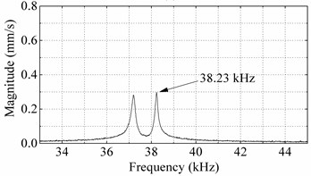
The prototype of the proposed motor used the three vibration modes presented in the second section. The longitudinal vibration mode will be excited by ceramic plate-1, 3 and ceramic plate-2, 4, respectively. Therefore, there are four vibrations need to be tested- two bending vibrations and two longitudinal vibrations. This experiment was executed by a scanning laser Doppler vibrometer (Psv-400-m2, Polytec, Germany), to obtain the actual resonance frequencies and vibration shapes. The vibration shapes and the frequency-magnitude curves of four exciting ways are shown in Fig. 10 and Fig. 11.
Fig. 10Bending vibration scanning results of the prototype: a) vibration velocity response spectrums under bending mode excited by ceramic-1 and ceramic-3, b) second order bending vibration shape excited by ceramic-1 and ceramic-3, c) vibration velocity response spectrums under bending mode excited by ceramic-2 and ceramic-4, d) second order bending vibration shape excited by ceramic-2 and ceramic-4
a)
b)
c)
d)
Fig. 10 shows that the practical resonance frequencies of two bending vibration modes are 38.04 kHz and 38.14 kHz, respectively, and their vibration shapes are all second order bending vibration. Fig. 11 shows that the vibration shapes of two longitudinal shapes and practical resonance frequencies are 38.19 kHz and 38.23 kHz, respectively. The resonance frequencies in this experiment are different from ones in the FEM analyses. It might result from the differences of materials and constraint condition in practice and the FEM, and also the fabricating and assembling errors. But the practical resonance frequencies of four vibrations are closed with each other and their vibration shapes are the same with the ones gained by the FEM analyses.
Fig. 11Longitudinal vibration scanning results of the prototype: a) vibration velocity response spectrums under longitudinal mode excited by ceramic-1 and ceramic-3, b) first order longitudinal vibration shape excited by ceramic-1 and ceramic-3, c) vibration velocity response spectrums under longitudinal mode excited by ceramic-2 and ceramic-4, d) first order longitudinal vibration excited by ceramic-2 and ceramic-4
a)
b)
c)
d)
4.2. Output characteristics test
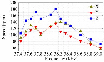
In order to obtain practical actuating capacity of the proposed motor, output velocities in three directions of the prototype were tested. Actuation of each direction was excited as the driving principle. And the runner was a steel ball with the diameter of 25 mm. Firstly, the frequency-velocity curves were obtained and shown in Fig. 12(a). The peak-to-peak amplitudes of driving signals applied were 100 V and the frequencies of the driving signals ranged from 37.45 kHz to 39.05 kHz. Although the frequency corresponding to the highest velocity of rotation along axis-X is 0.1 kHz higher than the ones of the other two, the velocity of rotation along axis-X corresponding to 38.15 kHz is just 2 rpm lower than the one corresponding to 38.25 kHz. Thus, the frequencies of driving signals were chosen as 38.15 kHz. With excited by these driving signals, the velocities of rotation along axis-X, Y and Z are 138 rpm, 135 rpm and 180 rpm, respectively.
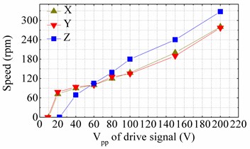
Secondly, the voltage-velocity curves were obtained and shown in Fig. 12(b). The frequencies of driving signals were 38.15 kHz and the peak-to-peak amplitudes of three driving signals ranged from zero to 200 V, to observe changes of velocity. It can be seen from the Fig. 11(b) that the velocities of rotation along three directions are in positive correlation with the amplitude of the driving signals. And the minimal amplitude needed to realize rotation along axis-X or Y is about half of the one needed to realize the rotation along axis-Z. Their starting voltages are 10 Vp-p, 9 Vp-p and 22 Vp-p, respectively. But after the rotation along axis-Z was excited, its velocity increased swiftly than the other two. The trends of rotation along axis-X and Y are similar. Under driving voltages of 200 Vp-p, the output velocities of three DOF can reach 280 rpm, 277 rpm and 327 rpm, respectively.
Fig. 12Mechanical output characteristics of the prototype: a) frequency-speed curves tested under driving signals with peak-to-peak voltages of 100 V, b) voltage-speed curves tested under driving signals with frequencies of 38.15 kHz
a)
b)
5. Conclusions
This paper proposes a novel three-DOF ultrasonic motor, which is based on the hybrids of two bending vibration modes and a longitudinal vibration mode. The driving principle is presented in this paper and verified to be feasible. In FEM analysis, fixed constraint was applied to the motor and resonance frequencies of selected vibration modes are 40.95 kHz and 41.12 kHz in finial dimensions, respectively. The proposed motor’s FEM and prototype are not identical, but the practical resonance frequencies are approximate. Through mechanical output tests, the proposed motor was found out to possess the characteristics of low starting voltages and high output velocities. And the piezoelectric ceramic plates in the proposed motor can be used to excite the bending vibration or the longitudinal vibration by different driving signals, which reduces the number of the piezoelectric ceramic plates, simplifies the structure of the proposed motor and make it easy to realize miniaturization. These characteristics make the proposed motor possesses practical utility.
References
-
He S. Y., Chiarot P. R., Park S. A single vibration mode tubular piezoelectric ultrasonic motor. IEEE Transactions on Ultrasonics, Ferroelectrics and Frequency Control, Vol. 58, Issue 5, 2011, p. 1049-1061.
-
Ueha S., Tomikawa Y., Kurosawa M., Nakamura N. Ultrasonic Motors Theory and Applications. Oxford, 1993.
-
Wai R. J., Lee J. D. Comparison of voltage-source resonant driving schemes for a linear piezoelectric ceramic motor. IEEE Transactions on Industrial Electronics, Vol. 55, Issue 2, 2008, p. 871-879.
-
Lin F. J., Hung Y. C., Chen S. Y. FPGA-based computed force control system using Elman neural network for linear ultrasonic motor. IEEE Transactions on Industrial Electronics, Vol. 56, Issue 4, 2009, p. 1238-1253.
-
Zhao C. S. Ultrasonic Motors Technologies and Applications. Beijing, 2007.
-
Yun C. H., Ishii T., Nakamura K., Ueha S., Akashi K. A high power ultrasonic linear motor using a longitudinal and bending hybrid bolt-clamped Langevin type transducer. Japanese Journal of Applied Physics, Vol. 40, Issue 5, 2001, p. 3773-3776.
-
Guo M. S., Pan S., Hu J. H., Zhao C. S., Dong S. X. A small linear ultrasonic motor utilizing longitudinal and bending modes of a piezoelectric tube. IEEE Transactions on Ultrasonics, Ferroelectrics and Frequency Control, Vol. 61, Issue 4, 2014, p. 705-709.
-
Wan Z. J., Hu H. Modeling and experimental analysis of the linear ultrasonic motor with in-plane bending and longitudinal mode. Ultrasonics, Vol. 54, Issue 3, 2014, p. 921-928.
-
Li X., Yao Z. Y., Wu R. C. Modeling and sticking motion analysis of a vibro-impact system in linear ultrasonic motors. International Journal of Mechanical Sciences, Vol. 100, 2015, p. 23-31.
-
Cheol Ho Y., Watson B., Friend J. A piezoelectric ultrasonic linear micromotor using a slotted stator. IEEE Transactions on Ultrasonics, Vol. 57, Issue 8, 2010, p. 1868-1874.
-
Liu Y. X., Xu D. M., Yang X. H., Chen W. S. Miniaturized piezoelectric actuator operating in bending hybrid modes. Sensors and Actuators A: Physical, Vol. 235, 2015, p. 158-164.
-
Liu Y. X., Chen W. S., Liu J. K., Shi S. J. A high-power linear ultrasonic motor using longitudinal vibration transducers with single foot, IEEE Transactions on Ultrasonics, Ferroelectrics and Frequency Control, Vol. 57, Issue 8, 2010, p. 1860-1867.
-
Liu Y. X., Chen W. S., Liu J. K., Shi S. J. A rectangle-type linear ultrasonic motor using longitudinal vibration transducers with four driving feet. IEEE Transactions on Ultrasonics, Ferroelectrics and Frequency Control, Vol. 60, Issue 4, 2013, p. 777-785.
-
Asumi K., Fukunaga R., Fujimura T., Kurosawa M. K. Miniaturization of a V-shape transducer ultrasonic motor. Japanese Journal of Applied Physics, Vol. 48, Issue 7, 2009, p. 07GM02.
-
Liu Y. X., Chen W. S., Feng P. L., Liu J. K. A rotary piezoelectric motor using bending vibrators. Sensors and Actuators A: Physical, Vol. 196, 2013, p. 48-54.
-
Chen W. S., Liu Y. X., Yang X. H., Liu J. K. Ring-type traveling wave ultrasonic motor using a radial bending mode. IEEE Transactions on Ultrasonics, Ferroelectrics and Frequency Control, Vol. 61, 2014, p. 197-202.
-
Liu Y. X., Chen W. S., Yang X. H., Liu J. K. A rotary piezoelectric actuator using the third and fourth bending vibration modes. IEEE Transactions on Industrial Electronics, Vol. 61, 2014, p. 4366-4373.
-
Liu Y. X., Liu J. K., Chen W. S., Feng P. L. A square-type rotary ultrasonic motor using longitudinal modes. Journal of Electroceramics, Vol. 33, 2014, p. 69-74.
-
Liu Y. X., Xu D. M., Yu Z. Y., Yan J. P., Yang X. H., Chen W. S. A novel rotary piezoelectric motor using first bending hybrid transducers. Applied Sciences, Vol. 5, 2015, p. 472-484.
-
Hoshina M., Mashimo T., Fukaya N. I., Matsubara O., Toyama S. Spherical ultrasonic motor drive system for camera orientation in pipe inspection. Advanced Robotics, Vol. 27, Issue 3, 2013, p. 199-209.
-
Ishii T., Mochizuki S., Shimizu T. Multi-mode langevin transducers for π-shapedultrasonic motor with multi-degree of freedom. IEEE International Ultrasonics Symposium Proceedings, 2013, p. 1563-1565.
-
Shen S. C., Chang S. J., Pan C. T., Huang J. C., Tsai P. C. Design and fabrication of a multi-degree-of-freedom microactuatorusing symmetric piezoelectric pusher element and its applications. IEEE/SICE International Symposium on System Integration, 2012, p. 686-691.
-
Khoo T. F., Dang D. H., Friend J., Oetomo D., Yeo L. Triple degree-of-freedom piezoelectric ultrasonic micromotor via flexural-axial coupled vibration. IEEE Transactions on Ultrasonics, Ferroelectrics and Frequency Control, Vol. 56, 2009, p. 1716-1724.
-
Takemura K., Park S., Maeno T. Control of multi-DOF ultrasonic actuator for dexterous surgical instrument. Journal of Sound and Vibration, Vol. 311, 2008, p. 652-666.
-
Li Z. R., Zhao C. S., Huang W. Q., Li Z. L. Several key issues in developing of cylinder type 3-DOF ultrasonic motor. Sensors and Actuators A: Physical, Vol. 136, 2007, p. 704-709.
Cited by
About this article
This work was supported in part by the National Natural Science Foundation of China (No. 51622502 and No. 51475112), in part by the Foundation for the Author of National Excellent Doctoral Dissertation of China (No. 201428), in part by the Foundation for Innovative Research Groups of the National Natural Science Foundation of China (No. 51521003) and in part by the Fok Ying Tung Education Foundation (No. 151053).
